
Complete Technical Guide
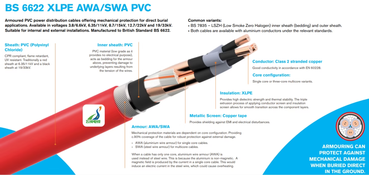
What is BS 6622 XLPE AWA/SWA PVC Cable?
A comprehensive technical guide to British Standard medium voltage armoured power cables for underground and industrial power distribution applications.
1. Introduction and Purpose
BS 6622 cables represent the British Standard specification for armoured power cables with thermosetting insulation, designed for medium voltage power distribution applications. These cables serve as the critical infrastructure backbone for transmitting electrical power in industrial, commercial, and utility installations where reliable performance under demanding conditions is essential.
The primary purpose of BS 6622 XLPE AWA/SWA PVC cables is to provide mechanically protected power transmission for fixed installations, including underground networks, direct burial applications, cable ducting systems, and industrial power distribution infrastructure. According to industry specifications, these cables are manufactured for rated voltages ranging from 3.8/6.6 kV (7.2 kV) to 19/33 kV (36 kV), making them suitable for medium voltage distribution networks worldwide.
Key Standard Reference: BS 6622:2007 specifies requirements and test methods for the construction, dimensions, and mechanical and electrical properties of armoured cables with thermosetting insulation, designed for a maximum continuous conductor operating temperature of 90°C and a maximum short circuit conductor temperature of 250°C.
2. Voltage Ratings and Classifications
BS 6622 cables are manufactured across a standardised range of voltage ratings to accommodate various power distribution requirements. The voltage designation system uses the format Uo/U (Um), where Uo represents the rated power-frequency voltage between conductor and earth, U represents the rated power-frequency voltage between conductors, and Um represents the maximum system voltage.
| Voltage Rating Uo/U (Um) | System Voltage Class | Typical Applications | Traditional Sheath Colour |
|---|---|---|---|
| 3.8/6.6 kV (7.2 kV) | 6.6 kV Class | Industrial plants, commercial buildings | Red or Black |
| 6.35/11 kV (12 kV) | 11 kV Class | Primary distribution networks, substations | Red |
| 8.7/15 kV (17.5 kV) | 15 kV Class | Regional distribution, industrial complexes | Black |
| 12.7/22 kV (24 kV) | 22 kV Class | Urban distribution, infrastructure projects | Black |
| 19/33 kV (36 kV) | 33 kV Class | High-capacity distribution, renewable energy | Black |
3. Material Structure and Construction
The construction of BS 6622 cables follows a precisely engineered layer structure, with each component serving specific electrical, mechanical, or protective functions. Understanding this construction is essential for proper specification and installation.
Conductor
Class 2 stranded copper or aluminium conductors conforming to EN 60228. Provides excellent conductivity with cross-sectional areas typically ranging from 35mm² to 1000mm².
Conductor Screen
Semi-conductive XLPE layer applied via triple extrusion process. Ensures smooth electric field distribution and prevents partial discharge at conductor surface.
Insulation (XLPE)
Cross-linked polyethylene insulation provides high dielectric strength and thermal stability. Operating temperature: 90°C continuous, 250°C short circuit.
Insulation Screen
Semi-conductive XLPE layer ensuring uniform electric field distribution. Facilitates smooth transition across component layers.
Metallic Screen
Copper tape or wire screen providing electromagnetic interference (EMI) shielding and earth fault current path. Approximately 90% coverage.
Inner Sheath (Bedding)
PVC material acting as bedding layer for armour. Prevents mechanical damage to underlying layers from armour wire tension.
Armour (AWA/SWA)
Mechanical protection: AWA (aluminium wire armour) for single core cables; SWA (steel wire armour) for multicore cables. Provides approximately 90% coverage.
Outer Sheath (PVC)
Polyvinyl Chloride outer sheath providing environmental protection. CPR compliant, flame retardant, and UV resistant.
3.1 Armour Selection: AWA vs SWA
The choice between aluminium wire armour (AWA) and steel wire armour (SWA) is technically mandated based on core configuration, not merely a preference consideration.
| Parameter | AWA (Aluminium Wire Armour) | SWA (Steel Wire Armour) |
|---|---|---|
| Core Configuration | Single core cables only | Multicore cables (3-core typical) |
| Magnetic Properties | Non-magnetic (essential requirement) | Magnetic (acceptable for balanced loads) |
| Reason for Selection | Prevents induced currents from magnetic field | Cost-effective, high mechanical strength |
| Weight Comparison | Approximately 65% lighter | Heavier but more robust |
| Corrosion Resistance | Natural oxide layer protection | Requires galvanisation |
⚠ Critical Engineering Note
Single core cables must use aluminium wire armour (AWA) rather than steel. The current flowing through a single core cable produces a magnetic field that would induce electrical currents in ferromagnetic steel armour, potentially causing overheating and cable failure. Aluminium’s non-magnetic properties eliminate this hazard.
4. Technical Specifications and Parameters
4.1 Electrical Parameters
| Parameter | Specification | Standard Reference |
|---|---|---|
| Voltage Rating Range | 3.8/6.6 kV to 19/33 kV | BS 6622 |
| Insulation Resistance | ≥20 MΩ·km at 20°C | IEC 60502-2 |
| Conductor Resistance (Copper) | Per EN 60228 Class 2 | EN 60228 |
| Dielectric Loss Factor (tan δ) | ≤0.004 at 20°C | BS 6622 |
| Partial Discharge | ≤5 pC at 1.5 Uo | IEC 60502-2 |
4.2 Thermal Parameters
| Operating Condition | Temperature | Duration/Notes |
|---|---|---|
| Maximum Continuous Operating | 90°C | Conductor temperature |
| Short Circuit Temperature | 250°C | Maximum 5 seconds duration |
| Minimum Installation Temperature | -5°C (PVC sheath) | Without preheating |
| Minimum Installation Temperature | -20°C (PE sheath) | Enhanced cold flexibility |
| Operating Temperature Range | -15°C to +90°C | Continuous service |
4.3 Mechanical Parameters
| Parameter | Single Core Cable | Three Core Cable |
|---|---|---|
| Minimum Bending Radius (Fixed) | 15 × OD | 12 × OD |
| Bending Radius (Adjacent to Termination) | 12 × OD | 10 × OD |
| Armour Coverage | ≈90% | ≈90% |
| Maximum Pulling Tension | 50 N/mm² on conductor cross-section | |
4.4 Current Carrying Capacity Reference (6.35/11kV, Copper Conductor)
| Cross-Section (mm²) | In Ground (Trefoil) A | In Ground (Flat) A | In Air (Trefoil) A |
|---|---|---|---|
| 50 | 165 | 175 | 205 |
| 95 | 245 | 265 | 305 |
| 185 | 370 | 405 | 475 |
| 300 | 480 | 530 | 620 |
| 500 | 615 | 680 | 800 |
Reference conditions: Ground temperature 20°C, ambient air 30°C, soil thermal resistivity 1.5 K·m/W, burial depth 0.8m.
5. Standards Compliance and Certifications
BS 6622 cables are manufactured to comply with multiple international and regional standards, ensuring quality, safety, and interoperability across global markets.
| Standard | Description | Application |
|---|---|---|
| BS 6622:2007 | Primary British Standard for armoured MV cables | Cable construction, testing requirements |
| IEC 60502-2 | International standard for MV cables 6kV-30kV | Type testing, routine testing |
| EN 60228 | Conductor specifications | Class 2 stranded conductors |
| BS EN 60332-1-2 | Flame retardancy testing | Single cable vertical flame test |
| CPR (EU 305/2011) | Construction Products Regulation | Fire performance classification |
| BS 7835 | LSZH variant specification | Low smoke zero halogen cables |
6. Installation and Application Guidelines
6.1 Suitable Installation Methods
BS 6622 cables are engineered for versatile installation across multiple environments and methods:
Direct Burial
Armour protection enables direct ground burial without additional mechanical protection. Standard burial depth: 0.8m minimum.
Cable Ducting
Suitable for installation in underground cable ducts and conduits. MDPE sheath variant preferred for duct applications.
Cable Tray Installation
Industrial applications with cable tray systems. Consider spacing requirements for thermal de-rating.
Indoor Installation
Power stations, switchboards, commercial buildings. CPR compliance required for EU installations.
6.2 Primary Application Sectors
These cables serve critical roles across numerous industries. Industry leaders in industrial reeling applications recognise the importance of proper cable specification for demanding environments. Similarly, specialists in mining cable applications understand that cable selection directly impacts operational safety and efficiency.
| Application Sector | Typical Use Cases | Key Requirements |
|---|---|---|
| Utility Power Distribution | Substation feeders, primary distribution networks | High reliability, long service life |
| Industrial Complexes | Factory power supply, process equipment | Mechanical protection, chemical resistance |
| Renewable Energy | Wind farm collection networks, solar plant interconnection | UV resistance, direct burial capability |
| Infrastructure Projects | Railways, airports, ports, highways | Long-term durability, maintenance access |
| Commercial Buildings | High-rise power distribution, data centres | Fire performance, space efficiency |
For applications involving port crane and maritime installations, proper cable specification ensures reliable operation in harsh coastal environments. Additionally, resources from South American mining cable specialists provide valuable insights into demanding extraction industry requirements.
7. Safety Thresholds and Critical Parameters
⚠ Critical Safety Thresholds
Exceeding these parameters may result in cable damage, system failure, or safety hazards. All installations must be designed with appropriate safety margins.
| Parameter | Maximum Safe Value | Consequence of Exceeding |
|---|---|---|
| Conductor Temperature (Continuous) | 90°C | Accelerated insulation ageing, reduced lifespan |
| Short Circuit Temperature | 250°C (max 5 sec) | Insulation damage, potential fire hazard |
| Minimum Bending Radius | 12-15 × OD | Conductor damage, insulation cracking |
| Maximum Installation Temperature | 60°C | Mechanical stress, installation damage |
| Sidewall Pressure (Installation) | 7300 N/m radius | Jacket crushing, conductor deformation |
| Maximum Pulling Tension | 50 N/mm² | Conductor elongation, armour damage |
7.1 De-rating Factors
Current carrying capacity must be adjusted based on installation conditions:
| Condition | De-rating Factor |
|---|---|
| Ambient Air Temperature 40°C | 0.88 |
| Ambient Air Temperature 50°C | 0.78 |
| Ground Temperature 30°C | 0.96 |
| Ground Temperature 40°C | 0.87 |
| Soil Thermal Resistivity 2.5 K·m/W | 0.83 |
| Two Circuits Touching | 0.80 |
8. Installation Precautions and Best Practices
✓ Pre-Installation Requirements
Verify cable integrity before installation. Conduct insulation resistance testing and visual inspection for any transport damage. Ensure ambient temperature is within installation limits.
8.1 Handling and Storage
Proper cable handling is essential to prevent installation damage and ensure long-term reliability:
Store cable drums on firm, level ground. Protect from direct sunlight, moisture ingress, and mechanical damage. Maintain storage temperature between -25°C and +50°C. Rotate drums periodically during extended storage periods exceeding six months.
8.2 Installation Requirements
Follow these critical installation parameters to ensure safe, compliant installations:
Observe minimum bending radius requirements at all times during installation. Use appropriate pulling equipment with dynamometer to monitor tension. Apply cable pulling lubricant for conduit installations to reduce sidewall pressure. Install cable markers and route identification at regular intervals per local regulations.
8.3 Jointing and Termination
Use only approved accessories designed for BS 6622 cables. Ensure all joints and terminations are performed by qualified personnel following manufacturer instructions. Test completed joints for insulation resistance before energisation. Document all jointing activities with location, date, and personnel records.
⚠ UV Exposure Notice
PVC outer sheaths may experience colour fading when exposed to prolonged ultraviolet radiation. While this does not affect electrical performance, consider MDPE sheath variants for applications with significant outdoor exposure, or apply additional UV protection measures.
9. Common Variants and Alternatives
| Variant | Standard | Key Difference | Application |
|---|---|---|---|
| BS 7835 LSZH | BS 7835 | Low Smoke Zero Halogen sheath | Tunnels, enclosed spaces, public buildings |
| MDPE Sheath | BS 6622 | Medium Density Polyethylene outer sheath | Enhanced UV resistance, ducting |
| Aluminium Conductor | BS 6622 | AL conductors per EN 60228 | Cost-sensitive installations, weight reduction |
| Triplex Formation | BS 6622 | Three single cores twisted together | Large cross-sections, flexible routing |
10. Frequently Asked Questions
Request Technical Support or Quotation
Our engineering team at Anhui Feichun Special Cable Co., Ltd. provides expert guidance on BS 6622 cable specification, custom manufacturing, and technical support for your medium voltage projects.
References and Further Resources
This technical guide references information from multiple authoritative industry sources. For further information on specific applications:
For port and maritime cable applications: Crane Cable Solutions
For mining industry cable specifications: Australian Mining Cable Standards
For reeling and festoon cable systems: Industrial Reeling Cable Guide
For South American mining applications: Chile Mining Cable Resources
For additional Feichun product information: Feichun Cable Main Site
External standard references: British Standards Institution, International Electrotechnical Commission
Industry cable suppliers: Eland Cables, Cleveland Cable Company


[…] What is BS 6622 XLPE AWA/SWA PVC Cable?[18] […]