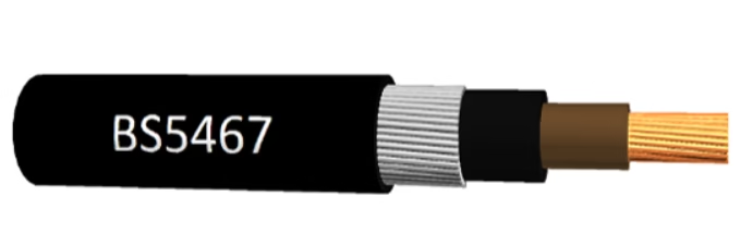
steel wire armoured cable

Geographic & Operational Context: Chuquicamata (Codelco) is transitioning from the world's largest open-pit copper mine to underground block caving (autonomous underground mining system). Depths: 700–1,500 meters below surface (Phase 1), expanding to 2,500+ meters (long-term). El Teniente (Codelco) is already operating at extreme depths: primary block caving at 2,000–2,500 m elevation below surface. Both mines employ: (1) Block caving gravity feed (fragmented ore flows down to cave level), (2) Mobile equipment (diesel-electric LHDs—Load-Haul-Dump vehicles, 30–50 ton capacity), (3) Fixed hoisting infrastructure (vertical shafts, incline decline haulage), (4) Extensive underground electrical distribution: 11 kV primary feeders, 6.6 kV secondaries, 3.3 kV distribution to mobile substations. 楚基卡马塔(国铜矿公司Codelco)正在从全球最大露天铜矿向地下自然崩落法(自主地下采矿系统)转型。深度:地表以下700-1,500米(第1阶段),长期扩展至2,500+米。El Teniente(Codelco)已在极端深度运营:地表下2,000-2,500m主自然崩落区。两座矿山采用:(1)重力进给式自然崩落(碎矿由高处流下至崩落区)、(2)移动设备(柴油-电动LHD-装-运-卸车、30-50吨容量)、(3)固定提升基础设施(竖井、倾斜下降运输)、(4)广泛的地下电气配电:11 kV一级馈电、6.6 kV二级、3.3 kV配电至移动变电站。 Type 2S Selection Rationale: Underground fixed-installation feeders (in contrast to dragline/shovel trailing cables) experience: (1) Rock fall hazard (loose fragments falling from roof, occasional collapses), (2) Equipment impact (LHD vehicles occasionally strike cable trays during positioning), (3) Long service life (5–10+ years without planned removal), (4) Static or semi-static routing (no continuous reel cycling). Type 2S SWA (Steel Wire Armoured) is optimal because: (1) Mechanical armour (galvanized steel wire spiral) provides exceptional impact protection, (2) Symmetrical earth architecture supports high-impedance grounded distribution systems, (3) Heavy construction (11 ton/km total weight) means higher copper content → lower resistance → reduced voltage drop over long feeder runs.

AS/NZS 1972 Type 2S 11kV 3x185mm² SWA Armoured Feeder Cable for Chile Underground Copper Mines

Geographic & Operational Context: Chuquicamata (Codelco) is transitioning from the world’s largest open-pit copper mine to underground block caving (autonomous underground mining system). Depths: 700–1,500 meters below surface (Phase 1), expanding to 2,500+ meters (long-term). El Teniente (Codelco) is already operating at extreme depths: primary block caving at 2,000–2,500 m elevation below surface. Both mines employ: (1) Block caving gravity feed (fragmented ore flows down to cave level), (2) Mobile equipment (diesel-electric LHDs—Load-Haul-Dump vehicles, 30–50 ton capacity), (3) Fixed hoisting infrastructure (vertical shafts, incline decline haulage), (4) Extensive underground electrical distribution: 11 kV primary feeders, 6.6 kV secondaries, 3.3 kV distribution to mobile substations. 楚基卡马塔(国铜矿公司Codelco)正在从全球最大露天铜矿向地下自然崩落法(自主地下采矿系统)转型。深度:地表以下700-1,500米(第1阶段),长期扩展至2,500+米。El Teniente(Codelco)已在极端深度运营:地表下2,000-2,500m主自然崩落区。两座矿山采用:(1)重力进给式自然崩落(碎矿由高处流下至崩落区)、(2)移动设备(柴油-电动LHD-装-运-卸车、30-50吨容量)、(3)固定提升基础设施(竖井、倾斜下降运输)、(4)广泛的地下电气配电:11 kV一级馈电、6.6 kV二级、3.3 kV配电至移动变电站。 Type 2S Selection Rationale: Underground fixed-installation feeders (in contrast to dragline/shovel trailing cables) experience: (1) Rock fall hazard (loose fragments falling from roof, occasional collapses), (2) Equipment impact (LHD vehicles occasionally strike cable trays during positioning), (3) Long service life (5–10+ years without planned removal), (4) Static or semi-static routing (no continuous reel cycling). Type 2S SWA (Steel Wire Armoured) is optimal because: (1) Mechanical armour (galvanized steel wire spiral) provides exceptional impact protection, (2) Symmetrical earth architecture supports high-impedance grounded distribution systems, (3) Heavy construction (11 ton/km total weight) means higher copper content → lower resistance → reduced voltage drop over long feeder runs.
In underground coal mining across Australia and New Zealand, selecting between AS/NZS 1802 and AS/NZS 1972 is not a matter of personal preference or cost optimization—it is a matter of electrical safety compliance and regulatory requirement. The decision tree, however, is surprisingly straightforward once you understand the single fundamental principle that separates these two standards: whether your equipment moves while energized. 在澳大利亚和新西兰的地下煤矿电气设计中,在AS/NZS 1802和AS/NZS 1972之间选择不是个人偏好或成本优化的问题——这是电气安全合规性和监管要求的问题。然而,一旦您理解分离这两个标准的单一基本原则,决策树就会变得出奇地直接:您的设备在通电时是否移动。

AS/NZS 1802 vs AS/NZS 1972: Which Australian Standard Applies to Your Underground Mining Equipment?

In underground coal mining across Australia and New Zealand, selecting between AS/NZS 1802 and AS/NZS 1972 is not a matter of personal preference or cost optimization—it is a matter of electrical safety compliance and regulatory requirement. The decision tree, however, is surprisingly straightforward once you understand the single fundamental principle that separates these two standards: whether your equipment moves while energized. 在澳大利亚和新西兰的地下煤矿电气设计中,在AS/NZS 1802和AS/NZS 1972之间选择不是个人偏好或成本优化的问题——这是电气安全合规性和监管要求的问题。然而,一旦您理解分离这两个标准的单一基本原则,决策树就会变得出奇地直接:您的设备在通电时是否移动。
The Type 2S 11kV 3x95mm² cable has a base ampacity of 285 amperes when installed in free air at 40°C ambient temperature. However, in a typical underground mine substation where three or more feeder cables are installed side-by-side on a cable ladder, the practical usable current is reduced to approximately 228 amperes through application of temperature and grouping derating factors. This 228 A figure is the number that should govern your design calculations and equipment sizing for the substation feeder. Type 2S 11kV 3x95mm² 电缆在 40°C 环境温度的自由空气中安装时,其基础载流量为 285 安培。但在地下矿山变电站中,三根或更多馈电电缆并排安装在电缆桥架上的典型情况下,通过应用温度和编组降额系数,实际可用电流减少至约 228 安培。这个 228 A 的数字应该管理您的设计计算和变电站馈电的设备选型。

Ampacity Derating: Sizing Type 2S 11kV 3x95mm² for Underground Mine Substations (Ambient 40°C)

The Type 2S 11kV 3x95mm² cable has a base ampacity of 285 amperes when installed in free air at 40°C ambient temperature. However, in a typical underground mine substation where three or more feeder cables are installed side-by-side on a cable ladder, the practical usable current is reduced to approximately 228 amperes through application of temperature and grouping derating factors. This 228 A figure is the number that should govern your design calculations and equipment sizing for the substation feeder. Type 2S 11kV 3x95mm² 电缆在 40°C 环境温度的自由空气中安装时,其基础载流量为 285 安培。但在地下矿山变电站中,三根或更多馈电电缆并排安装在电缆桥架上的典型情况下,通过应用温度和编组降额系数,实际可用电流减少至约 228 安培。这个 228 A 的数字应该管理您的设计计算和变电站馈电的设备选型。
The nominal outer diameter (OD) of an AS/NZS 1972 Type 2S 11kV 3x185mm² feeder cable is 76.0 to 80.0 millimeters (3.0 to 3.15 inches). The typical design center for Feichun's Type 2S 3x185mm² product is approximately 78.6 mm. This measurement is taken across the outermost surface of the flame-retardant PVC sheath, which forms the final protective layer after the galvanized steel wire armour (SWA) and inner insulation geometry. 澳标 AS/NZS 1972 Type 2S 11kV 3x185mm² 馈电电缆的标称外径为 76.0 至 80.0 毫米(3.0 至 3.15 英寸)。 Feichun Type 2S 3x185mm² 产品的典型设计中心约为 78.6 mm。该测量是在钢丝铠装 (SWA) 和内层绝缘几何结构之后,在阻燃 PVC 外护套的最外表面进行的。 This 76–80 mm range is not arbitrary—it represents the accumulated thicknesses of multiple cable components layered concentrically around the three power conductors. To understand where this dimension comes from, an electrical engineer planning a mine installation must understand the contribution of each layer.

Outer Diameter Specs: What is the Nominal OD for AS/NZS 1972 Type 2S 11kV 3x185mm² Feeder Cable?

The nominal outer diameter (OD) of an AS/NZS 1972 Type 2S 11kV 3x185mm² feeder cable is 76.0 to 80.0 millimeters (3.0 to 3.15 inches). The typical design center for Feichun’s Type 2S 3x185mm² product is approximately 78.6 mm. This measurement is taken across the outermost surface of the flame-retardant PVC sheath, which forms the final protective layer after the galvanized steel wire armour (SWA) and inner insulation geometry. 澳标 AS/NZS 1972 Type 2S 11kV 3x185mm² 馈电电缆的标称外径为 76.0 至 80.0 毫米(3.0 至 3.15 英寸)。 Feichun Type 2S 3x185mm² 产品的典型设计中心约为 78.6 mm。该测量是在钢丝铠装 (SWA) 和内层绝缘几何结构之后,在阻燃 PVC 外护套的最外表面进行的。 This 76–80 mm range is not arbitrary—it represents the accumulated thicknesses of multiple cable components layered concentrically around the three power conductors. To understand where this dimension comes from, an electrical engineer planning a mine installation must understand the contribution of each layer.
The Single Most Important Cable Design Decision in Underground Coal Mining: Whether the cable employs collective screening (Type 2) or individual phase screening (Type 2S). This single engineering choice directly determines whether a mechanical cable failure will result in a phase-to-earth fault (detected and stopped in milliseconds) or a phase-to-phase fault with thousands of amperes of arc current (igniting methane explosions).

Type 2 vs Type 2S: Why the “S” (Individual Screen) is Mandatory for 11kV Underground Coal Mines

The Single Most Important Cable Design Decision in Underground Coal Mining: Whether the cable employs collective screening (Type 2) or individual phase screening (Type 2S). This single engineering choice directly determines whether a mechanical cable failure will result in a phase-to-earth fault (detected and stopped in milliseconds) or a phase-to-phase fault with thousands of amperes of arc current (igniting methane explosions).
Overland conveyor systems represent critical infrastructure for bulk material handling across mining, quarrying, and heavy industrial operations. When these systems extend beyond 5 kilometers, the selection of appropriate power distribution cables becomes a paramount engineering decision that directly impacts operational reliability, maintenance costs, and system longevity. According to industry standards published by the International Electrotechnical Commission, power cables for such applications must meet rigorous mechanical and electrical performance criteria to withstand the demanding operational environment. This technical analysis examines two primary cable architectures utilized in extended overland conveyor applications: armoured cables and flexible cables. Each design philosophy addresses specific operational requirements, with armoured configurations prioritizing mechanical protection for fixed installations, while flexible designs accommodate dynamic loading and continuous motion requirements. The selection between these cable types fundamentally depends on installation methodology, environmental conditions, mechanical stress profiles, and long-term operational economics.

Overland Conveyor Systems: Armoured vs. Flexible Cables for 5km+ Power Distribution

Overland conveyor systems represent critical infrastructure for bulk material handling across mining, quarrying, and heavy industrial operations. When these systems extend beyond 5 kilometers, the selection of appropriate power distribution cables becomes a paramount engineering decision that directly impacts operational reliability, maintenance costs, and system longevity. According to industry standards published by the International Electrotechnical Commission, power cables for such applications must meet rigorous mechanical and electrical performance criteria to withstand the demanding operational environment. This technical analysis examines two primary cable architectures utilized in extended overland conveyor applications: armoured cables and flexible cables. Each design philosophy addresses specific operational requirements, with armoured configurations prioritizing mechanical protection for fixed installations, while flexible designs accommodate dynamic loading and continuous motion requirements. The selection between these cable types fundamentally depends on installation methodology, environmental conditions, mechanical stress profiles, and long-term operational economics.
(N)TSKCGEWÖU specifications. This protective layer serves multiple critical functions within the cable assembly, with mechanical stress redistribution being among its most important roles. According to research published by Sibelco, the bedding compound is defined as the material applied around insulated conductors to maintain their position and provide bedding for protective armoring.[1] This layer functions as an intermediary component positioned between the laid-up cores and the metallic armor, creating what cable engineers describe as a separation sheath that fundamentally alters how mechanical forces are distributed throughout the cable structure.

Inner Sheath Function: Mechanical Stress Redistribution in (N)TSKCGEWÖU Cables

(N)TSKCGEWÖU specifications. This protective layer serves multiple critical functions within the cable assembly, with mechanical stress redistribution being among its most important roles. According to research published by Sibelco, the bedding compound is defined as the material applied around insulated conductors to maintain their position and provide bedding for protective armoring.[1] This layer functions as an intermediary component positioned between the laid-up cores and the metallic armor, creating what cable engineers describe as a separation sheath that fundamentally alters how mechanical forces are distributed throughout the cable structure.
How do you select conductor size for high-current tunnelling equipment and cable reels?

كيفية اختيار مقاس الموصل لمعدات الأنفاق عالية التيار وبكرات الكابلات؟

Selecting the correct conductor size for cables used in tunnel boring equipment and cable reels is critical for ensuring safety and operational efficiency. These cables are subjected to extreme conditions including high currents, mechanical stress, and elevated temperatures. According to International Electrotechnical Commission (IEC) standards, conductor selection must consider ampacity, voltage drop, short-circuit capacity, and environmental factors.
DIN VDE 0276 is the widely used German standard for cables with extruded insulation used in power distribution systems. Developed by the VDE (Verband der Elektrotechnik, Elektronik und Informationstechnik e.V.), this comprehensive standard covers a significant percentage of power cables used across the European continent, establishing construction requirements, dimensional specifications, and test methods for both low voltage (0.6/1 kV) and medium voltage (up to 18/30 kV) power cables.

What is DIN VDE 0276 Cable?

VDE 0276 電纜的技術規格對於正確選擇和安裝至關重要。XLPE 絕緣電纜允許的連續工作溫度高達 90°C,短路溫度可達 250°C,優於 PVC 絕緣電纜的 70°C 和 160°C。導體採用符合 IEC 60228 第 2 類標準的絞合壓縮圓形銅或鋁導體。導體屏蔽層為擠出的半導電材料,最小厚度 0.3mm,在 90°C 時體積電阻率不超過 500 Ω·m。彎曲半徑要求根據電纜類型不同而變化:無金屬護套電纜為 15 倍外徑,帶鋁護套電纜為 30 倍外徑。
BS6724 is a British Standard specification for thermosetting insulated, armoured cables with rated voltages of 600/1000V and 1900/3300V, specifically designed to have low emission of smoke and corrosive gases when affected by fire. This standard is widely adopted in the UK and internationally for applications where fire safety is critical.

What is BS6724 Cable?

BS6724, BS 6724, BS6724 cable, BS6724 standard, BS 6724 cable specification, BS6724 LSZH cable, BS6724 SWA cable, BS6724 AWA cable, 600/1000V cable, 1900/3300V cable, 0.6/1kV cable, 1.9/3.3kV cable, low voltage cable BS6724,BS6724電纜, 低煙無鹵電纜, LSZH電纜, 低壓電纜, 鎧裝電纜, 鋼絲鎧裝電纜, 鋁絲鎧裝電纜, 阻燃電纜, 防火電纜, 公共建築電纜, 醫院電纜, 機場電纜, 隧道電纜, 數據中心電纜, 特種電纜, 電力電纜
BS6622 is the British Standard specification for single-core and multicore cables with extruded cross-linked polyethylene (XLPE) insulation for rated voltages from 6.35/11kV up to 19/33kV. These medium voltage (MV) cables are specifically designed for power distribution networks, underground installations, and cable ducting applications. The standard ensures consistent quality, safety, and performance across all compliant products.

What is BS6622 Cable?

BS6622 cable specification, BS6622 cable datasheet, BS6622 cable price, BS6622 cable manufacturer, BS6622 cable supplier China, 19/33kV XLPE cable, 33kV armoured cable, medium voltage cable for underground, BS6622 three core cable, BS6622 single core cable, XLPE/PVC/SWA/PVC cable, BS6622 cable dimensions, BS6622 cable weight per meter, BS6622 cable current carrying capacity,BS6622電纜, 中壓電纜, 交聯聚乙烯電纜, XLPE電纜, 鎧裝電纜, 鋼絲鎧裝電纜, 鋁絲鎧裝電纜, 地下電纜, 直埋電纜, 配電電纜, 11kV電纜, 33kV電纜, 中壓配電電纜, 特種電纜, 電力電纜
British Standard BS5467 specifies the requirements for low voltage armoured cables with thermosetting insulation rated at 600/1000V for fixed installations. These cables feature galvanised steel wire armour (SWA) for multi-core configurations and non-magnetic aluminium wire armour (AWA) for single-core applications. The standard encompasses cables with 1 to 48 cores, utilizing either plain annealed stranded copper (Class 2) or solid aluminium (Class 1) conductors per BS 6360/IEC 60228. The cross-linked polyethylene (XLPE) insulation ensures stable operation at maximum conductor temperatures of 90°C continuous and 250°C during short-circuit conditions.

What is BS5467 Cable?

BS5467 cable, BS5467 armoured cable, BS5467 SWA cable, SWA power cable, XLPE armoured cable, 0.6/1kV cable, low voltage armoured cable, steel wire armoured cable, AWA cable, underground burial cable, direct burial power cable, industrial power cable, British Standard cable, IEC 60502-1, BASEC approved, thermosetting insulation cable, PVC sheathed cable, UV resistant cable, mechanical protection cable, mains distribution cable, 3 core armoured cable, 4 core armoured cable, multi-core power cable, copper conductor cable, BS5467 cable specifications, BS5467 current rating, cable for mining, construction site cable, infrastructure cable, outdoor installation cable, BS5467電纜, 鋼絲鎧裝電纜, XLPE電纜, 低壓電力電纜, 直埋電纜, 工業電纜, 安徽飛純電纜, 特種電纜
SANS 1520 Feichun Cable

CU/XLPE/LSZH/SWA/LSZH-SANS 1507 0.6/1KVBlack Sheath with White Strip Cable

The CU/XLPE/LSZH/SWA/LSZH-SANS 1507 0.6/1KV cable with black sheath and white identification strip represents a significant advancement in industrial power transmission technology. This specialized cable combines the robust mechanical protection of steel wire armour (SWA) with the critical safety features of Low Smoke Zero Halogen (LSZH) materials, making it an optimal choice for demanding applications in mining operations, petrochemical facilities, and infrastructure projects across South Africa and internationally.
CEI 20-27 CENELEC HD361 Cable

What is CEI 20-27 CENELEC HD361 Cable?

CEI 20-27 CENELEC HD361 represents a standardized cable designation system developed by the European Committee for Electrotechnical Standardisation (CENELEC) to provide uniform identification and classification of harmonized power cables and cords across European markets. This systematic coding methodology enables engineers, procurement specialists, and electrical contractors to precisely identify cable specifications including voltage ratings, insulation materials, conductor types, and sheathing compounds through a structured alphanumeric designation format.