
Comprehensive ampacity derating methodology for Type 2S 11kV 3x95mm² feeder cables in underground coal mine substations operating at 40°C ambient temperature. Temperature derating factors, grouping derating analysis, cable ladder installation constraints, practical sizing calculations, and design considerations for safe feeder cable selection.
地下煤矿变电站 40°C 环境温度下 Type 2S 11kV 3x95mm² 馈电电缆的完整载流量降额方法论。温度降额系数、编组降额分析、电缆桥架安装约束、实际选型计算以及安全馈电电缆选择的设计考虑。
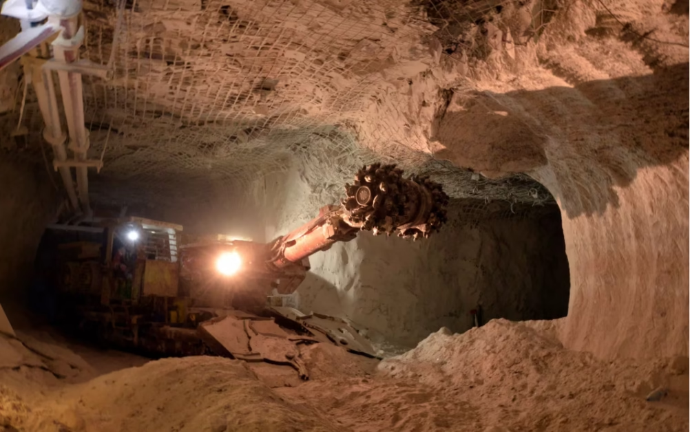
Ampacity Derating: Sizing Type 2S 11kV 3x95mm² for Underground Mine Substations (Ambient 40°C)
Comprehensive ampacity derating methodology for Type 2S 11kV 3x95mm² feeder cables in underground coal mine substations operating at 40°C ambient temperature. Temperature derating factors, grouping derating analysis, cable ladder installation constraints, practical sizing calculations, and design considerations for safe feeder cable selection.
地下煤矿变电站 40°C 环境温度下 Type 2S 11kV 3x95mm² 馈电电缆的完整载流量降额方法论。温度降额系数、编组降额分析、电缆桥架安装约束、实际选型计算以及安全馈电电缆选择的设计考虑。
1. Direct Answer: The Usable Ampacity After Derating
The Type 2S 11kV 3x95mm² cable has a base ampacity of 285 amperes when installed in free air at 40°C ambient temperature. However, in a typical underground mine substation where three or more feeder cables are installed side-by-side on a cable ladder, the practical usable current is reduced to approximately 228 amperes through application of temperature and grouping derating factors. This 228 A figure is the number that should govern your design calculations and equipment sizing for the substation feeder.
Type 2S 11kV 3x95mm² 电缆在 40°C 环境温度的自由空气中安装时,其基础载流量为 285 安培。但在地下矿山变电站中,三根或更多馈电电缆并排安装在电缆桥架上的典型情况下,通过应用温度和编组降额系数,实际可用电流减少至约 228 安培。这个 228 A 的数字应该管理您的设计计算和变电站馈电的设备选型。
The reduction from 285 A to 228 A represents a derating of approximately 20 percent. This is not a small margin, and it illustrates why understanding the derating calculation is essential for engineers designing underground mining electrical systems. Many engineers look at the cable’s nameplate rating of 285 A and assume that is what the cable can safely carry in the mine. This assumption is incorrect and dangerous. The derating factors are not suggestions or conservative safety margins—they are mandatory constraints imposed by AS/NZS 3008, the Australian standard governing cable selection, and they reflect the real physics of heat generation and dissipation in cables installed in constrained environments.
2. Why Cable Ampacity Is Not a Single Number
To understand why the ampacity must be “derated,” it helps to think about what happens physically inside the cable when current flows through it. A cable carrying electrical current generates heat. This is unavoidable—it is a consequence of the resistance of the copper conductor to the flow of electrons. The amount of heat generated is proportional to the square of the current (Joule heating: P = I² R). The warmer the conductor gets, the faster its resistance increases, and at some point, the insulation material (XLPE, in this case) begins to degrade.
XLPE insulation has a maximum rated temperature—typically 90°C in mining applications. This does not mean the conductor can never exceed 90°C without immediately failing, but it means that sustained operation above 90°C will shorten the cable’s life and eventually cause insulation breakdown. Therefore, the fundamental constraint in sizing a cable is ensuring that the conductor temperature stays below its rated maximum, even under the worst-case ambient conditions the cable will experience.
Here is the key insight: the ampacity rating of 285 A is valid only under specific assumed conditions—in this case, a single cable in free air at a 40°C ambient temperature with no other heat sources nearby. If you change any of those conditions, the safe current that the cable can carry changes. Add another cable next to it, and the two cables’ heat begins to trap each other’s warmth, raising the conductor temperature for the same current. Increase the ambient temperature from 40°C to 50°C, and the conductor starts at a higher baseline temperature, requiring lower current to avoid exceeding the 90°C limit. These are not design choices or engineering opinions—they are thermodynamic facts.
Think of ampacity like a speed limit on a road. The base ampacity (285 A) is like a speed limit of 100 km/h on a dry, straight highway at noon. That limit is safe under those specific conditions. But if it starts raining, the road becomes wet, and the speed limit should be reduced to 80 km/h. If it is nighttime and visibility is poor, the limit should be even lower. The speed limit does not change arbitrarily—it changes because the conditions have changed and the safe speed has changed. Similarly, cable ampacity does not arbitrarily change; it changes because the thermal conditions have changed and the safe current has changed.
3. Understanding Base Ampacity: The 285 A Reference Point
The base ampacity of 285 amperes for a Type 2S 11kV 3x95mm² cable comes from AS/NZS 3008.1.1, the Australian electrical installations standard that governs cable selection. This standard includes extensive tables of current-carrying capacities for various cable types, conductor sizes, and installation methods. The 285 A figure is derived through a calculation that considers the conductor’s resistance, the insulation thickness, the assumed rate of heat dissipation, and the target conductor temperature of 90°C.
The assumptions embedded in this 285 A figure are very specific. The cable is assumed to be installed in free air (not in a conduit, not buried, not surrounded by other cables). The ambient temperature is assumed to be 40°C. The cable is assumed to be a single isolated conductor with no neighboring cables contributing heat. Under these precise conditions, a current of 285 amperes will result in a conductor temperature of approximately 90°C—right at the limit of the XLPE insulation rating.
Here is a crucial point that many engineers miss: the 40°C assumption is not a warm temperature that requires derating. It is actually the reference temperature at which the base ampacity is defined. If your mine substation operates at exactly 40°C ambient temperature, you do not apply a temperature derating factor. The temperature derating factor only applies if the actual ambient temperature differs from this 40°C reference. If the actual temperature is higher (say, 50°C), you derate downward. If the actual temperature is lower (say, 30°C), you would theoretically uprate the cable (though in practice, conservative design rarely takes advantage of uprating).
4. Temperature Derating: Why 40°C Is Neither Good Nor Bad
The temperature derating factor is perhaps the most straightforward component of the derating calculation, and yet it is often misunderstood. Let us walk through the logic carefully.
When you select a cable size, you are essentially saying: “I want the conductor to stay below 90°C under all expected operating conditions.” The conductor temperature is determined by two sources of heat: the heat generated by the cable’s own resistance (I² R losses), and the ambient temperature surrounding the cable. If the ambient temperature increases, the baseline temperature of the conductor increases. To compensate and keep the conductor from exceeding 90°C, you must reduce the current.
The relationship between ambient temperature and required derating is approximately linear over the typical range of mine temperatures. The standard provides derating factors for various ambient temperatures. At exactly 40°C (the reference temperature), the derating factor is 1.0—meaning no derating is applied. This is not because 40°C is a special “safe” temperature; it is simply the reference point from which deviations are measured.
If your mine substation operates at 45°C ambient (perhaps due to limited ventilation near the transformer location), the derating factor becomes approximately 0.95. This means you multiply the base ampacity by 0.95: 285 A × 0.95 ≈ 270 A. If the ambient temperature rises to 50°C, the derating factor drops to approximately 0.89, giving 285 A × 0.89 ≈ 253 A. Each 5°C increase in ambient temperature results in roughly a 10–12 A reduction in usable ampacity.
Many engineers estimate the substation ambient temperature based on general mine conditions or past experience. This is a mistake. The actual ambient temperature at the cable installation location can be significantly higher than the general mine temperature due to heat radiated from the transformer, switchgear, and other equipment. Before applying the temperature derating factor, physically measure the ambient air temperature at the cable tray location using a calibrated thermometer over a representative time period (at least one week, capturing day and night cycles and variations in mine load). If measurements show 45°C or higher, the derating implications are severe and may require larger cable sizes than initially planned.
5. The Grouping Derating Factor: The Hidden Constraint Engineers Overlook
The grouping derating factor is where many engineers make critical design errors, because it is less intuitive than temperature derating and because it is easy to underestimate how severely it impacts ampacity. Let us build up an understanding of this factor step by step.
Imagine a single Type 2S 3x95mm² cable lying on a cable tray in a mine substation. Heat flows away from the cable in all directions—upward into the air, downward into the tray, and sideways into the surrounding air. The cable is well-cooled because the heat has many paths to dissipate. This is the ideal scenario, and it corresponds to the base ampacity of 285 A.
Now add a second feeder cable of the same size on the same tray, positioned directly adjacent (side by side) to the first cable. The second cable is now generating its own heat. But more importantly, the heat radiated by the first cable now encounters the surface of the second cable instead of dissipating into open air. The second cable’s presence blocks heat from escaping from the first cable. Similarly, the first cable blocks heat from escaping the second cable. The result is that both cables run hotter than they would individually, even though no additional current is flowing through either one. To keep both cables below their 90°C limit, you must reduce the current through each one.
Add a third cable adjacent to the first two, and the situation becomes even more constrained. The cables in the middle of the group (physically surrounded by neighbors on more sides) run significantly hotter than the cables on the edges. By AS/NZS 3008 standards, when three single-core or three-core cables are installed in a single layer, side by side, in contact with each other on a tray, the grouping derating factor is typically 0.80. This means each cable’s ampacity is multiplied by 0.80 to account for the reduced cooling.
Here is the critical point: in most underground mine substations, the main cable tray supporting the primary feeders carries not just one cable, but three, four, or sometimes five main feeders running to different load centers in the mine. The grouping derating factor of 0.80 is not an exception; it is the normal operating condition. Yet many engineers design as if the cables are isolated, using the base 285 A, and only realize after installation that the cables are running hotter than expected.
6. Putting It Together: The Multiplication Formula
The usable ampacity of a cable is calculated by multiplying the base ampacity by a series of derating factors. Each factor accounts for a different aspect of the installation environment. The formula is straightforward, but its application requires careful attention to the actual conditions.
This 228 A is the safe, conservative ampacity you should use for design calculations. It represents the current at which the cable will remain below its 90°C rated temperature under normal operating conditions with three cables on the tray. This is the number you specify in the substation load flow analysis, switchgear coordination studies, and protection system settings.
7. Practical Example: A Real Substation Feeder Installation
Let us walk through a realistic mine substation design scenario to see how derating works in practice. This will ground the abstract calculations in a concrete engineering problem.
The Scenario: Your mine is constructing a new secondary substation 500 meters underground, supplied by a primary 11kV feeder from the main pit substation. The secondary substation will distribute power to three load centers: (1) the continuous mining machine circuit, (2) the ventilation fan circuit, and (3) the general underground infrastructure circuit. Each circuit requires its own feeder cable from the secondary substation. The engineer is tasked with selecting the cable cross-section for the continuous miner feeder, which is expected to carry a steady load of 200 amperes under normal conditions and up to 220 amperes during peak demand periods.
Initial (Incorrect) Design Approach: The engineer looks at the base ampacity of a Type 2S 3x95mm² cable (285 A) and thinks: “Great, 285 A > 220 A, so the 3x95mm² cable is adequate.” The purchase order is placed, and the cable is installed on the main substation tray alongside two other main feeders (one to ventilation, one to general infrastructure).
What Actually Happens: Once energized, the substation monitoring system logs the conductor temperature of the 3x95mm² feeder during the first week of operation. The continuous miner is drawing 210 amperes (normal load). The engineer expects the conductor to be well below 90°C. But the actual measured temperature reaches 85°C under normal load and 92°C during peak demand. The cable is running hotter than expected because of the grouping derating factor that was not accounted for during design.
Correct Design Approach (Retroactive Analysis): The engineer recalculates. The three feeders on the tray create a grouping derating factor of 0.80. The substation ambient temperature, measured at the cable tray, averages 40°C. Therefore: Usable Ampacity = 285 A × 1.0 × 0.80 = 228 A. The peak demand of 220 A is dangerously close to this limit, leaving only 8 A of margin. In fact, accounting for normal variations and transient peaks, 220 A is marginal at best and unsafe at worst. The correct choice would have been to upsize to a Type 2S 3x120mm² cable, which has a base ampacity of 310 A. With the same derating factors: 310 A × 1.0 × 0.80 = 248 A. This provides reasonable margin above the 220 A peak demand.
This example illustrates a common engineering error: confusing base ampacity with usable ampacity. The base ampacity of 285 A is not meaningless, but it is only valid under conditions that rarely exist in mine substations. The grouping derating factor of 0.80 is not an exception; it is the normal condition whenever multiple feeders share a common tray.
8. Scenario Analysis: What If Temperature Is Higher Than 40°C?
Let us examine what happens if the substation environment is warmer than the assumed 40°C baseline. This is not an unlikely scenario in underground mines, where ventilation around secondary substations can be limited.
Scenario A: 45°C Ambient Temperature
The secondary substation is located in a closed heading with limited forced ventilation. Measurements show the ambient temperature at the cable tray averages 45°C. The derating factor for 45°C is approximately 0.95. The calculation becomes: Usable Ampacity = 285 A × 0.95 × 0.80 = 216 A. Compare this to the 40°C scenario (228 A): the 5°C temperature increase costs you 12 amperes of capacity—more than 5 percent reduction. For the continuous miner feeder expecting 220 A peak demand, this is now clearly inadequate. The 3x95mm² cable is no longer suitable, and a larger cross-section is necessary.
Scenario B: 50°C Ambient Temperature
A particularly poorly ventilated substation location (perhaps near a geothermal hot spot or with inadequate cooling design) reaches 50°C ambient. The derating factor drops to approximately 0.89. Usable Ampacity = 285 A × 0.89 × 0.80 = 203 A. For a 220 A design load, this cable is completely unsuitable. The engineer must upsize to 3x120mm² or 3x150mm², depending on margin requirements. The cascade of constraints—grouping + high temperature—makes the original 3x95mm² choice untenable.
When designing feeder cables for underground substations, always conduct a temperature survey before finalizing cable selection. Measure ambient temperature at the actual cable tray location over at least one week, capturing peak thermal conditions (e.g., during shift changes when load and ventilation are heaviest). If measured temperature exceeds 40°C, explicitly apply the temperature derating factor in your calculations. Many projects have experienced cable overheating and inadequate capacity because engineers assumed 40°C without verification.
9. Cable Tray Design and Thermal Considerations
The grouping derating factor does not appear randomly from standards documents; it is rooted in thermal physics and the geometry of cable installation. Understanding this connection helps engineers make better design decisions about cable routing and tray layout.
When cables are installed on a ladder-type tray (the most common configuration in mines), they rest on the rungs of the ladder, with air circulating between and around them. The thermal resistance of the path from the cable conductor to the ambient air determines how fast heat can dissipate. A single cable has a relatively low thermal resistance path (heat radiates directly to the surrounding air on all sides). Two cables adjacent to each other have a higher thermal resistance because heat from one cable radiates toward the other cable (which is at a similar temperature) rather than toward the cooler ambient air. Three cables in a row have even higher thermal resistance because the middle cable is essentially thermally trapped.
Tray layout engineers can sometimes reduce the grouping derating impact by strategic cable spacing. For instance, if instead of placing three cables in contact on a single layer, the tray design separates them into two layers (one cable on top, two spaced below), or spaces them further apart longitudinally, the grouping factor can improve from 0.80 toward 0.85 or higher. However, this requires careful planning and coordination with the substation layout.
Another consideration is tray ventilation. If the mine’s ventilation strategy ensures fresh, cooler air flows directly over the cable tray (rather than air that has already been warmed by equipment), the effective ambient temperature at the cables is reduced, and derating requirements ease. However, relying on ventilation is risky for design—if the ventilation system fails or is compromised, the cables suddenly experience the unmittigated ambient temperature. Conservative design accounts for ventilation failure scenarios.
10. Heat Dissipation Physics: Why Grouping Matters More Than You Think
To truly understand ampacity derating, it helps to appreciate the underlying physics of heat transfer. Cable heating is governed by three mechanisms: conduction (heat flowing directly through material), convection (heat carried away by air movement), and radiation (heat emitted as electromagnetic energy). In the context of cable ampacity, convection is the dominant cooling mechanism—the surrounding air carries away the heat generated by resistance losses in the conductor.
The heat dissipation rate is proportional to the surface area of the cable exposed to the moving air and the temperature difference between the cable surface and the ambient air (Newton’s law of cooling). When a single cable is installed in free air, the entire circumference of the cable is exposed to moving air, and heat dissipates efficiently. When three cables are bunched together, the surfaces where cables contact each other are no longer exposed to air and cannot dissipate heat. The effective dissipation area is significantly reduced.
The grouping derating factor of 0.80 for three cables reflects the fact that the heat dissipation area is reduced by roughly 20 percent compared to isolated cables (accounting for contact areas and reduced air circulation). To maintain the same conductor temperature, the heat generation (which is proportional to I²) must be reduced by 20 percent, which corresponds to a current reduction of roughly 10 percent (since √0.80 ≈ 0.894). This is the physics behind the derating numbers.
11. Conservative Design Margins and Safety Factors
The derating factors in AS/NZS 3008 are derived from laboratory measurements and field experience, but they represent typical conditions, not worst-case scenarios. In practice, conservative engineers often apply additional safety margins beyond the standard derating factors.
For example, if the standard calculation yields an ampacity of 228 A, a conservative designer might select a cable sized for 200 A continuous load, leaving 28 A (12 percent) of additional margin. This provides a buffer for transient loads above the nominal maximum, temperature measurement uncertainty, and future load growth.
Conversely, cost-conscious designers sometimes try to load cables closer to the calculated ampacity. Designing a cable for 225 A when the calculated derating is 228 A leaves almost no margin. This is a false economy—the cost savings from a slightly smaller cable are typically offset by risk of overheating, reduced cable life, and potential thermal cycling stresses. The standard recommendation is to operate continuously at no more than 80–90 percent of the derated ampacity, leaving adequate margin for variability.
12. Conclusion: Proper Derating Ensures Safe, Reliable Feeder Cables
The Type 2S 11kV 3x95mm² cable has a base ampacity of 285 amperes, but in typical underground mine substation environments with multiple feeders sharing a tray and ambient temperatures around 40°C, the practical usable ampacity is approximately 228 amperes. This derating—a reduction of about 20 percent—is not conservative padding; it is a reflection of real thermal constraints imposed by the installation environment.
Proper cable sizing for underground mine substations requires that electrical engineers understand and correctly apply both temperature and grouping derating factors. Failure to do so results in cables that run hotter than rated, premature insulation degradation, and potential failures during peak demand periods. Conversely, correct derating ensures that the cable operates safely throughout its service life, maintaining the thermal and electrical reliability that mining operations depend on.
When designing feeder cables for your mine substation, Feichun recommends that you work with a qualified electrical engineer to perform a complete derating analysis specific to your installation conditions. Measure the ambient temperature at the cable location, determine the number of feeders that will share the tray, and apply the appropriate derating factors. Feichun’s technical support team can assist in this analysis and help you select the optimal cable cross-section for your application. The investment in proper engineering upfront prevents costly problems during operation.


