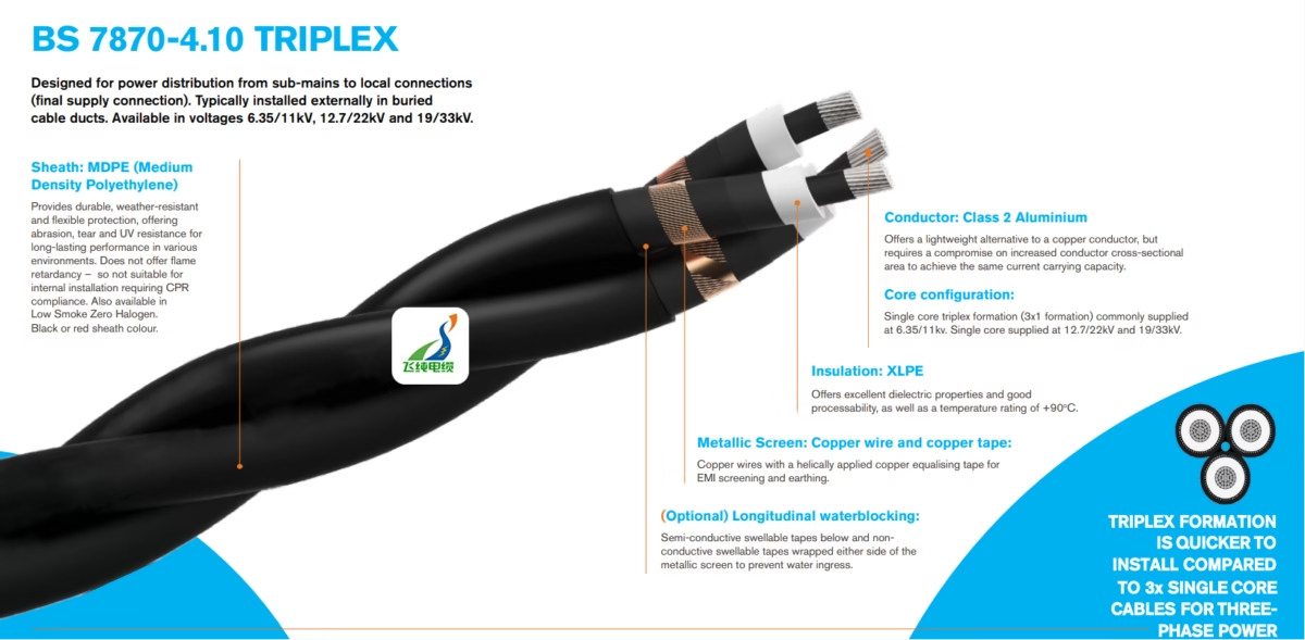
What is BS 7870-4.10 TRIPLEX Cable?

BS 6622 cable, XLPE insulation, AWA armour, SWA cable, medium voltage cable, 11kV cable, 33kV power cable, underground cable, direct burial cable
What is BS 7870-4.10 TRIPLEX Cable? Complete Technical Guide | Feichun Cable

What is BS 7870-4.10 TRIPLEX Cable?

Complete Technical Guide for Medium Voltage Power Distribution

Anhui Feichun Special Cable Co., Ltd.

安徽飞纯特种电缆有限公司

Professional Manufacturer of High-Quality Medium Voltage Distribution Cables

1. Introduction to BS 7870-4.10 TRIPLEX Cable

BS 7870-4.10 TRIPLEX cable represents a specialized category of medium voltage power distribution cables designed specifically for utility and industrial applications. According to the British Standards Institution, BS 7870-4.10 specifies requirements for distribution cables with extruded insulation rated from 11 kV to 33 kV. The TRIPLEX formation consists of three single-core cables laid together, providing a more efficient installation solution compared to individually pulled single-core cables.

These cables are predominantly utilized by Distribution Network Operators (DNOs) and Independent Distribution Network Operators (IDNOs) throughout the United Kingdom and internationally for primary power distribution from sub-main connections to local supply networks. The standard encompasses voltage ratings of 6.35/11kV, 12.7/22kV, and 19/33kV, making it suitable for various medium voltage distribution applications.

[8] Cables & Wires Ltd. “Cable Installation Guidelines – Best Practices” (Cables & Wires, 2024)

8. Common Problems and Troubleshooting Solutions

8.1 Installation-Related Issues

ProblemCausePrevention/Solution
Sheath Cracking During InstallationInstallation at temperature below 0°C, excessive bending, over-tensioningWarm cables to above 0°C before installation, monitor pulling tensions, respect minimum bending radius. Replace damaged sections.
Insulation Damage During PullingSharp edges in ducts, excessive pulling force, inadequate lubricationInspect and smooth duct entries, use pulling compound, monitor tension continuously. Perform electrical tests after installation to detect damage.
Incorrect Phase IdentificationPoor marking, confusion during jointingMaintain clear phase marking throughout installation, verify phasing before energization using proper test equipment
Joint/Termination Failure During TestingPoor workmanship, contamination, inadequate stress controlUse factory-trained jointers, maintain clean working environment, follow manufacturer instructions precisely. Discard contaminated components.

8.2 In-Service Operational Issues

8.2.1 Premature Failure Mechanisms

Medium voltage cable failures typically manifest through several well-documented mechanisms:

Primary Failure Modes and Mitigation:

1. Water Treeing (Long-term Degradation):

  • Mechanism: Microscopic tree-like channels form in XLPE insulation when exposed to moisture and electrical stress over years
  • Risk Factors: Moisture ingress, high humidity environments, voltage stress concentration points
  • Prevention: Specify longitudinal water blocking for moisture-prone installations, use water-tree-retardant XLPE formulations, ensure proper joint sealing
  • Detection: Tan delta (dissipation factor) testing can identify early-stage degradation

2. Partial Discharge Activity:

  • Mechanism: Voids or contamination in insulation or at joints cause localized electrical breakdown
  • Risk Factors: Poor jointing workmanship, insulation defects, inadequate stress control
  • Prevention: Stringent quality control during manufacturing and installation, comprehensive post-installation PD testing
  • Detection: Online PD monitoring systems can provide early warning before failure

3. Thermal Overload:

  • Mechanism: Sustained operation above rated current causes insulation degradation
  • Risk Factors: Undersized cable selection, poor soil thermal conditions, excessive ambient temperature
  • Prevention: Proper cable sizing calculations accounting for all installation factors, periodic thermal monitoring
  • Detection: Distributed Temperature Sensing (DTS) systems can identify hotspots

4. Mechanical Damage:

  • Mechanism: Third-party excavation, ground movement, or installation damage
  • Risk Factors: Inadequate burial depth, poor route marking, unstable ground conditions
  • Prevention: Proper cable route documentation, installation of marker posts, adequate mechanical protection
  • Detection: Cable fault location systems can pinpoint damage location for repair

8.3 Fault Location and Diagnosis

When cable faults occur, rapid location and diagnosis minimize downtime and repair costs:

Fault TypeSymptomsLocation MethodRepair Approach
Complete Breakdown (Phase-to-Earth)Circuit breaker trip, zero insulation resistanceTime Domain Reflectometry (TDR), Impulse Current Method (ICM), Acoustic detectionExcavate, install straight-through joint or replacement section
High Resistance FaultIntermittent trips, degraded insulation resistanceVoltage surge method, burning down to solid fault for conventional locationJoint installation at fault location
Screen/Sheath FaultElevated earth leakage current, corrosion indicatorsSheath fault location equipmentInstall local repair sleeve if accessible, monitor if not critical
Joint FailureOften manifests as tracking or complete breakdownKnown joint locations, thermal imagingReplace failed joint with new assembly

8.4 Routine Maintenance and Condition Monitoring

Proactive maintenance programs significantly extend cable service life. For critical circuits, consider implementing:

  • Annual Insulation Resistance Testing: Trending of insulation resistance values can identify gradual degradation
  • Tan Delta Testing (3-5 year intervals): Dissipation factor measurements detect water treeing and insulation aging
  • Partial Discharge Monitoring: Online or periodic offline PD testing identifies developing issues before failure
  • Thermal Imaging: Annual infrared surveys of accessible joints and terminations detect overheating
  • Visual Inspection: Regular inspection of accessible cable routes and above-ground sections for physical damage, vermin activity, or environmental degradation

8.5 Aging Infrastructure Considerations

As cables approach their design life expectancy (typically 40+ years for modern XLPE cables), utilities face decisions about refurbishment versus replacement:

Life Extension Strategies:

  • Load Management: Reducing operational loads on aging cables can significantly extend remaining life
  • Joint Replacement Program: Joints often fail before cable sections; systematic joint replacement can add 10-15 years
  • Enhanced Monitoring: Increased monitoring frequency provides early warning and allows planned replacement rather than emergency repairs
  • Cable Rejuvenation: Experimental technologies such as silicone injection are being developed to reverse water tree formation, though not yet widely adopted

[9] IEEE Power & Energy Society. “Cable Condition Monitoring and Diagnostic Technologies – Review” (IEEE PES Technical Report, 2023)

9. Industry Applications and Performance Data

9.1 Mining and Heavy Industry Applications

The mining sector requires robust, reliable power distribution systems capable of operating in harsh environmental conditions. According to industry partners at Mining Cable CL and Amplex Mining Australia, BS 7870-4.10 TRIPLEX cables have demonstrated excellent performance in:

  • Underground Mine Power Distribution: Delivering power from surface substations to underground operations at depths exceeding 1000 meters
  • Open Pit Operations: Providing reliable power to mobile equipment, crushers, and conveyor systems in challenging outdoor environments
  • Processing Plants: Distributing medium voltage power to grinding mills, flotation systems, and auxiliary equipment
  • Renewable Integration: Connecting on-site solar installations and battery energy storage systems to mining infrastructure

9.2 Crane and Material Handling Systems

Industrial crane systems, as detailed by Crane Cable, utilize medium voltage distribution to supply power to high-capacity lifting equipment. The triplex configuration offers specific advantages:

Performance Benefits for Crane Applications:

  • Simplified Installation: Single-pull triplex reduces installation time by 35-40% in complex crane runway environments
  • Reduced Phase Imbalance: Fixed geometric spacing maintains consistent inductance, improving motor performance
  • Space Efficiency: Compact triplex configuration optimizes limited space in crane galleries and festoon systems
  • Electromagnetic Compatibility: Proper screening reduces interference with crane control systems

9.3 Renewable Energy Infrastructure

BS 7870-4.10 TRIPLEX cables play a crucial role in renewable energy projects:

ApplicationTypical VoltageKey RequirementsPerformance Data
Wind Farm Collection Networks11 kV, 33 kVWater blocking, long-term reliability, low maintenanceDesign life 25+ years, failure rate typically <0.5 faults per 100 km-year
Solar Farm Interconnection11 kV, 22 kVUV-resistant sheath for exposed sections, thermal performance in desert conditionsAmbient temperatures up to 50°C, direct burial or above-ground tray installation
Battery Energy Storage Systems11 kVFast installation, flexibility for expansionTriplex reduces installation time 30-40% vs separate singles
Hydroelectric Generator Connections11 kV, 22 kVHigh moisture resistance, fish-friendly installationsWaterblocking essential, polyethylene sheath preferred for environmental compatibility

9.4 Comparative Performance: Aluminium vs Copper Conductors

While copper offers superior conductivity, aluminium provides cost and weight advantages. The following comparison helps designers select the appropriate conductor:

ParameterCopper ConductorAluminium ConductorNotes
Electrical Conductivity100% (reference)61% of copperRequires 1.6× cross-section for equivalent ampacity
Density8.96 g/cm³2.70 g/cm³Aluminium cables significantly lighter
Cost (relative)Higher (typically 3-4× aluminum)LowerMaterial cost advantage for long cable runs
OxidationLess susceptibleForms oxide layerProper termination techniques essential for aluminium
Mechanical StrengthHigher tensile strengthLower tensile strengthAffects maximum pulling tension (50 N/mm² vs 25 N/mm²)
Thermal ExpansionLower coefficientHigher coefficientAluminum requires consideration of expansion in long runs

For typical DNO applications in the UK, aluminium conductors dominate due to cost considerations and established experience. Copper is typically specified for retrofit projects where existing duct capacity limits cable diameter or for installations requiring maximum ampacity in limited space.

[10] International Copper Association. “Copper vs Aluminium in Medium Voltage Distribution Systems – Technical Comparison” (ICA Technical Brief, 2023)

10. Conclusion: Why Choose BS 7870-4.10 TRIPLEX Cable

BS 7870-4.10 TRIPLEX cable represents the industry-standard solution for medium voltage power distribution in the 11 kV to 33 kV range. The combination of proven XLPE insulation technology, robust MDPE or LSZH sheathing, and efficient triplex formation delivers:

  • Cost-Effective Installation: 35-40% faster installation than separate single cores reduces labor costs
  • Long-Term Reliability: Modern XLPE cables achieve 40+ year service life with proper installation and maintenance
  • Operational Flexibility: Available in three voltage ratings (11 kV, 22 kV, 33 kV) to suit diverse applications
  • Environmental Durability: MDPE sheath provides excellent weather resistance for buried installations
  • Safety Compliance: Meets rigorous BS and IEC standards with comprehensive testing protocols
  • Maintenance Simplicity: Robust construction minimizes routine maintenance requirements

Manufactured by Anhui Feichun Special Cable Co., Ltd. to stringent quality standards, BS 7870-4.10 TRIPLEX cables serve critical power distribution infrastructure across industrial, utility, mining, renewable energy, and commercial sectors worldwide.

Whether you’re designing a new distribution network, upgrading aging infrastructure, or expanding renewable energy capacity, BS 7870-4.10 TRIPLEX cables deliver the performance, reliability, and value required for mission-critical medium voltage applications.

Contact Anhui Feichun Special Cable Co., Ltd.

For technical specifications, quotations, or project consultation on BS 7870-4.10 TRIPLEX cables and other specialized cable solutions:

Technical Support Email: [email protected]
Sales Inquiries: [email protected]
Project Management: [email protected]
WhatsApp: +86 13855 123218

Our technical team is available to provide detailed cable sizing calculations, installation guidance, and customized solutions for your specific application requirements.

class=”reference”>

[1] British Standards Institution. BS 7870-4.10: Specification for distribution cables with extruded insulation of rated voltages of 11 kV to 33 kV (Tratos Group, 2024)

2. Purpose and Applications

2.1 Primary Purpose

The BS 7870-4.10 TRIPLEX cable serves as the critical infrastructure component for distributing electrical power from high-voltage grid supply points to sub-main developments and ultimately to end-user properties. The cable’s primary functions include:

  • Power distribution from electrical grid connections to sub-main developments
  • Underground distribution networks for urban and suburban areas
  • Connection between substations and local distribution points
  • Industrial and commercial facility power supply systems
  • Renewable energy grid integration for wind and solar installations

2.2 Typical Installation Environments

Approved Installation Methods:

  • Direct burial in ground (most common application)
  • Installation in buried cable ducts and conduits
  • Free air installation when using appropriate support systems
  • Clipped directly to surfaces in controlled environments
  • Cable tray or basket systems for industrial installations

2.3 Industrial Applications

BS 7870-4.10 TRIPLEX cables find extensive use across multiple industrial sectors. Mining operations, as detailed by industry partners at miningcable.cl and amplexmining.com.au, require robust medium voltage distribution solutions for underground and surface operations. The cable’s durability and resistance to environmental factors make it particularly suitable for demanding mining environments where exposure to moisture, mechanical stress, and varying temperatures is common.

Similarly, crane and material handling systems, as documented by cranecable.com, utilize these cables for power distribution to heavy machinery and mobile equipment. The triplex configuration reduces installation complexity while maintaining the necessary electrical performance for high-power industrial applications.

[2] QZ Group. “Triplex 11 kV Cable for DNO (BS 7870-4.10 Series) Applications.” Cable Manufacturing Case Study (Cable-Uni, 2024)

3. Technical Characteristics and Performance Parameters

3.1 Voltage Ratings and Electrical Performance

Voltage Rating (U₀/U)Nominal System VoltageMaximum Operating VoltageTypical Applications
6.35/11 kV11 kV12 kVUrban/suburban distribution, industrial complexes
12.7/22 kV22 kV24 kVPrimary distribution networks, large facilities
19/33 kV33 kV36 kVHigh voltage distribution, generation utilities

3.2 Temperature Performance Specifications

Operating ConditionTemperature RatingDurationReference Standard
Continuous Operation+90°CContinuousBS 7870-1 Annex B
Emergency Overload+130°CLimited periodIEC 60502-2
Short Circuit (1 second)+250°C1 second maximumInternational standards
Installation Temperature0°C minimumDuring installationBS 7870-4.10
Low Temperature Flexibility-40°CMaterial propertyXLPE specification

3.3 Triplex Configuration Advantages

The triplex formation offers significant installation and operational benefits compared to traditional three separate single-core cables. According to industry analysis from reelingcable.com, the key performance advantages include:

Installation Efficiency Comparison:

  • Installation Time: Approximately 35-40% faster than pulling three separate single-core cables
  • Cable Handling: Single pull operation reduces labor requirements by 30-35%
  • Trench Utilization: More efficient use of duct space, reducing civil work costs by 20-25%
  • Phase Balance: Pre-assembled configuration ensures consistent spacing and reduces electromagnetic imbalance
  • Termination Simplicity: All three phases arrive simultaneously, streamlining connection procedures

[3] Eland Cables. “BS7870-4.10 Standard: Cable specifications and applications” (Eland Cables, 2024)

4. Material Structure and Construction Details

4.1 Conductor Specifications

ComponentSpecificationStandardTechnical Details
Conductor MaterialClass 2 Aluminium or Class 2 CopperBS EN 60228Stranded circular compacted or solid aluminium
Aluminium Cross-sections70 – 300 mm²Standard sizes70, 95, 120, 150, 185, 240, 300 mm²
Copper Cross-sections70 – 1000 mm²Standard sizesExtended range up to 1000 mm² for high current
Conductor ScreenSemi-conductive compoundBS 7870-1Extruded bonded or strippable layer

4.2 Insulation System

The insulation system represents the critical electrical barrier in BS 7870-4.10 TRIPLEX cables. Cross-Linked Polyethylene (XLPE) serves as the primary insulation material, offering superior electrical and thermal performance compared to traditional alternatives.

XLPE Insulation Properties (Type DIX 3 per BS 7870-1 Annex B):

PropertyValue/CharacteristicAdvantage
Dielectric StrengthHigh (low dissipation factor)Minimal dielectric losses, improved efficiency
Continuous Temperature90°CHigher current capacity than PVC (70°C)
Thermal StabilityMaintains properties to 250°C short-termSuperior fault current withstand capability
Moisture ResistanceExcellent (with water blocking)Enhanced reliability in wet environments
Chemical ResistanceResistant to acids, bases, oilsExtended service life in harsh conditions
Mechanical StrengthHigh tensile and impact resistanceDurability during installation and operation

According to research on XLPE cable materials, cross-linking significantly enhances the molecular stability of polyethylene, improving resistance to water treeing – a primary aging mechanism in medium voltage cables. Water-resistant XLPE formulations can extend cable service life from 20-25 years for standard XLPE to over 40 years for advanced tree-retardant compounds.

4.3 Metallic Screening System

The metallic screen serves multiple critical functions: electromagnetic interference (EMI) screening, fault current path, and equipotential grounding. BS 7870-4.10 specifies precise requirements for screen construction:

Screen ComponentConstructionCross-sectionFunction
Copper Wire ScreenHelically applied plain annealed copper wires35 mm² or 50 mm² (typical)Primary earth path and EMI shielding
Copper Equalising TapeHelically wound copper tapeVariable thicknessUniform field distribution and additional screening
Semi-conductive TapeUnder wire screen (optional)N/APrevents screen encapsulation in sheath

4.4 Water Blocking Technology

For installations in moisture-prone environments, longitudinal water blocking provides critical protection against moisture ingress that could compromise insulation integrity:

Water Blocking System Components:

  • Semi-conductive Swellable Tapes: Applied below the metallic screen to create a moisture barrier at the conductor interface
  • Non-conductive Swellable Tapes: Wrapped on either side of the metallic screen to prevent longitudinal water migration
  • Swelling Mechanism: Tapes absorb water and expand to form a gel barrier, blocking further moisture penetration
  • Application: Particularly critical for wind farm installations and submarine cable routes where water exposure is inevitable

4.5 Outer Sheath Options

Sheath TypeMaterial CodePropertiesApplications
MDPE (Type A)DMP 5 per BS 7870-1UV resistant, weather-resistant, flexible, durable. Black or red color.Standard for buried and outdoor installations. Not flame retardant – unsuitable for fixed building installations requiring CPR compliance.
LSZH (Type B)DMZ 4 per BS 7870-1Low smoke emission, zero halogen, flame retardant per BS EN 60332-1-2 and 60332-3-24Required for installations with fire safety requirements, tunnels, confined spaces, public buildings

4.6 Complete Layer Construction Sequence

From inner to outer layer, the BS 7870-4.10 TRIPLEX cable construction follows this precise sequence (as manufactured by Anhui Feichun Special Cable Co., Ltd.):

  1. Conductor: Class 2 stranded aluminium or copper conductor
  2. Conductor Screen: Extruded semi-conductive layer (bonded type)
  3. Insulation: XLPE Type DIX 3, applied by triple extrusion process
  4. Insulation Screen: Extruded semi-conductive layer (strippable or bonded)
  5. Water Blocking (Optional): Semi-conductive swellable tape
  6. Metallic Screen: Copper wire screen + copper equalising tape
  7. Water Blocking (Optional): Non-conductive swellable tapes
  8. Separator/Binder: Tape to prevent screen encapsulation
  9. Outer Sheath: MDPE or LSZH extruded jacket
  10. Marking: Continuous longitudinal marking with manufacturer, standard, size, year, and sequential meter marks

[4] Performance Wire. “XLPE Cable Properties and Applications” (Performance Wire, September 2024)

[5] ZMS Cable. “XLPE Material in Medium Voltage Cable – Technical Analysis” (ZMS Cable, 2024)

5. Compliance with International Standards

5.1 Primary Standards and Specifications

StandardTitle/ScopeKey Requirements
BS 7870-4.10Specification for distribution cables with extruded insulation (11kV-33kV)Construction, dimensions, electrical tests, performance requirements for DNO applications
BS 7870-1General requirements and test methodsMaterial specifications in Annex B (DIX 3 XLPE, DMP 5 MDPE, DMZ 4 LSZH, DIE 5 EPR)
BS EN 60228Conductors of insulated cablesClass 1 (solid) and Class 2 (stranded) conductor specifications
IEC 60502-2Power cables with extruded insulation (1kV-30kV)International equivalent, harmonized electrical requirements
HD 620 S2European harmonization documentPart 100 and Part 110 implemented by BS 7870-4.10

5.2 Fire Performance Standards (LSZH Type B Only)

Test StandardTest DescriptionRequirement
BS EN 60332-1-2Flame propagation on single vertical insulated wire/cableCable must self-extinguish within specified time
BS EN IEC 60332-3-24Flame propagation on bunched cables (Category C)Limited flame spread in cable bunches
BS EN 61034Smoke emission measurementMinimum light transmittance maintained during combustion
BS EN IEC 60754Acid gas emission and corrosivityLow acidity and conductivity of combustion gases

5.3 Electrical Testing Requirements

Before cables can be released for installation, they must pass rigorous type testing and routine production testing protocols:

Routine Electrical Tests (performed on every cable length):

  • Conductor DC Resistance: Verification of conductor sizing and material purity
  • Partial Discharge Test: Detection of insulation defects under applied voltage
  • AC Voltage Withstand: 4-hour test at elevated voltage to verify insulation integrity
  • DC Sheath Integrity: Testing of outer sheath for continuity and resistance

Type Tests (performed on representative samples for design approval):

  • Impulse Voltage Test: Lightning impulse (1.2/50 μs) and switching impulse testing
  • Thermal Aging: Extended exposure to elevated temperatures to verify long-term stability
  • Water Penetration: Longitudinal water blocking effectiveness verification
  • Mechanical Tests: Bending, tensile, impact, and crush tests
  • Short Circuit Test: Validation of conductor and screen capacity under fault conditions
  • Fire Performance: Flame propagation, smoke density, and acid gas tests (LSZH versions)

5.4 DNO-Specific Requirements

Individual Distribution Network Operators often supplement BS 7870-4.10 with additional specifications. For example, Western Power Distribution requires compliance with Engineering Specification EE82 in addition to BS 7870-4.10, which may specify particular screen sizes, sheath colors (red MDPE for WPD), or marking requirements.

Important Compliance Note: While BS 7870-4.10 provides the base standard, always verify specific DNO requirements before procurement. Screen cross-sectional areas, material thicknesses, and testing protocols may be customized to individual DNO specifications and are not necessarily interchangeable between different network operators.

[6] Tratos Group. “11 kV Single and Triplex Cable for Western Power Distribution – BS 7870-4.10 and EE82” (Tratos Group, February 2024)

6. Safety Thresholds and Operational Limits

6.1 Current Carrying Capacity

The current-carrying capacity (ampacity) of BS 7870-4.10 TRIPLEX cables depends on multiple factors including conductor size, installation method, ambient temperature, and soil thermal resistivity. The following table provides typical continuous current ratings:

Conductor SizeMaterialDirect Buried (90°C)In Ducts (90°C)In Air (90°C)
70 mm²Aluminium~195 A~175 A~210 A
95 mm²Aluminium~235 A~210 A~250 A
150 mm²Aluminium~305 A~270 A~325 A
185 mm²Aluminium~355 A~315 A~375 A
240 mm²Aluminium~425 A~375 A~450 A
300 mm²Aluminium~490 A~430 A~520 A

Note: These values are indicative for 11kV cables in typical installation conditions (soil thermal resistivity 1.0 K.m/W, ambient/soil temperature 20°C). Actual ratings must be calculated for specific project conditions using appropriate cable sizing software or standards such as IEC 60364-5-52.

6.2 Bending Radius Limitations

Minimum Bending Radius Requirements:

Installation ConditionMinimum Bending RadiusCalculation Method
During Installation15 × Overall Cable DiameterFor single core cables in triplex formation
Fixed Installation12 × Overall Cable DiameterAfter installation is complete
LSZH Sheath (Low Temp)20 × Overall Cable DiameterLSZH materials less flexible at low temperatures

Example: For a 185 mm² aluminium conductor cable with overall diameter of 45 mm, the minimum installation bending radius would be 15 × 45 mm = 675 mm (0.675 m).

6.3 Short Circuit Performance

The cable must withstand fault currents without damage to conductors or insulation:

ComponentShort Circuit Temperature LimitDurationDesign Consideration
XLPE Insulation250°C maximum1 secondConductor sizing must account for fault current magnitude and clearing time
Copper Wire Screen160°C (plain copper)1 secondScreen cross-section sized according to Table 6 in BS 7870-4.10
Aluminium ConductorThermal limit per BS 7870-4.101 secondShort circuit current capacity lower than copper, requires larger conductor for equivalent fault performance

6.4 Installation Temperature Limits

Critical Safety Requirement: Cables must not be handled or installed when cable temperature is below 0°C. At temperatures below freezing, MDPE and XLPE materials lose flexibility and risk cracking or mechanical damage during installation.

Storage and Handling: If cables have been stored in sub-zero conditions, they must be allowed to warm to above 0°C before installation commences. For LSZH sheathed cables, a higher minimum temperature (typically +5°C) is recommended due to the different material properties.

6.5 Voltage Stress and Insulation Margins

The cable’s insulation system is designed with safety margins to withstand various voltage stresses:

  • Normal Operating Voltage: Cable rated voltage (U₀/U) provides 15-20% margin above nominal system voltage
  • Temporary Overvoltage: Can withstand system overvoltages due to switching or ground faults for limited periods
  • Impulse Voltage: Withstands lightning impulses per BS 7870-4.10 impulse test requirements
  • Partial Discharge Extinction: Operates well below partial discharge inception voltage to ensure long-term reliability

6.6 Support Spacing for Aerial Installation

When cables are installed in free air or on cable supports rather than direct burial, appropriate support spacing must be maintained to prevent excessive sag and mechanical stress:

Installation AngleRecommended Maximum Support SpacingNotes
Horizontal0.5 – 1.0 m (depending on cable size)Closer spacing for heavier cables
Vertical (up to 30°)1.0 – 1.5 mWeight supported primarily by clamps
Vertical (over 30°)Use horizontal spacingCable weight creates significant tension

[7] Prysmian UK. “Product Guide – BS 7870-4.10 Cable Construction” (Prysmian, September 2024)

7. Precautions for Use and Installation Best Practices

7.1 Pre-Installation Inspection

Mandatory Checks Before Installation:

  • Verify cable drum labeling matches project specifications (voltage rating, conductor size, length)
  • Inspect outer sheath for visible damage from transport or storage
  • Check cable temperature is above 0°C (above +5°C for LSZH)
  • Confirm route survey completed and trenches/ducts prepared to correct dimensions
  • Verify pulling equipment rated for cable weight and tension limits
  • Ensure proper electrical test equipment available for post-installation verification

7.2 Cable Handling and Transportation

Drum Handling: Cable drums should be handled in accordance with BS 8512 guidelines. Key safety considerations include:

  • Use appropriate lifting equipment rated for drum weight (typical 11kV triplex drums weigh 2000-5000 kg when fully loaded)
  • Never drop drums or allow impact damage
  • Store drums on firm, level ground with drum flanges protected
  • Maintain drum rotation direction marked on flange during uncoiling
  • Secure drums during transport to prevent rolling or movement

7.3 Installation Method Selection

Installation MethodSuitable ConditionsKey Precautions
Direct BurialMost common for distribution cablesMinimum burial depth 600 mm, install warning tape 300 mm above cable, backfill with fine material free of sharp stones
Ducted InstallationUrban areas, road crossingsUse appropriate duct diameter (typically 1.5-2× cable OD), install pulling tape, apply pulling compound to reduce friction
Cable Tray/BasketIndustrial installations, cable galleriesMaintain support spacing per section 6.6, secure with appropriate cleats, allow for thermal expansion
Clipped DirectIndoor substations, wallsUse non-metallic cleats to avoid induced currents, maintain phase spacing, ensure adequate support

7.4 Pulling Tension Limitations

Maximum Pulling Tensions – Critical Safety Limits:

  • Copper Conductor: Maximum tension = 50 N/mm² of conductor cross-section
  • Aluminium Conductor: Maximum tension = 25 N/mm² of conductor cross-section (lower due to softer material)
  • Example for 185 mm² Al: Maximum pulling force = 25 × 185 = 4625 N (approximately 472 kg)

Exceeding these limits can cause conductor deformation, insulation damage, or sheath cracking. Always use tension monitoring equipment for long or difficult pulls.

7.5 Jointing and Termination Requirements

Medium voltage cable jointing and termination requires specialist skills and equipment. Only personnel qualified as “skilled persons” under the Electricity Safety, Quality and Continuity Regulations (ESQCR) should perform this work:

  • Joint Selection: Use joints and terminations specifically approved for BS 7870-4.10 cables and the installed voltage rating
  • Heat Shrink Technology: Most modern joints use heat shrink construction for indoor and outdoor applications
  • Cold Shrink Alternatives: Pre-expanded cold shrink joints available for situations where heat sources are prohibited
  • Stress Control: Critical to properly install stress control components at the insulation screen interface
  • Screen Continuity: Metallic screens must be properly connected through joints to maintain earth continuity
  • Environmental Sealing: Outdoor joints require appropriate environmental sealing against moisture ingress

7.6 Testing Before Energization

After installation and before connection to the network, comprehensive testing must verify cable integrity:

Test TypePurposeTypical Values/Criteria
Insulation ResistanceDetect gross insulation defectsMinimum 100 MΩ at installation voltage, typically much higher for new cables
DC High Voltage WithstandStress test insulation systemTypically 3-4× rated voltage AC equivalent, applied for 5-15 minutes
Partial DischargeDetect workmanship issues in joints/terminationsShould be below detectable limits at 1.5× rated voltage
Phase IdentificationVerify correct phase connectionsMust match system phasing and rotation
Screen ContinuityEnsure proper earth pathLow resistance connection throughout cable length

7.7 Environmental Considerations

  • Corrosive Soils: In acidic or alkaline soils, consider additional mechanical protection or increased burial depth
  • High Water Table: Ensure water blocking options specified for permanently wet installations
  • Mechanical Threats: Install protective slabs or ducts in areas subject to excavation or vehicular traffic
  • Thermal Environment: Account for heat sources (other cables, steam pipes) when calculating current capacity
  • UV Exposure: While MDPE sheaths are UV-resistant, prolonged exposure (months/years) can cause surface degradation. For long-term above-ground installations, consider UV-stabilized ducts or protective coatings

7.8 Decommissioning and Disposal

At end of service life, cables should be properly decommissioned and recycled:

  • De-energize and disconnect from supply system using established safety procedures
  • Copper and aluminium conductors have significant recycling value
  • XLPE and MDPE materials can be mechanically recycled into secondary products
  • Properly dispose of any materials that cannot be recycled per local environmental regulations
Control & Instrumentation Cable Specification _ Anhui Feichun Special Cable Co., Ltd_下载
Previous Article

What is BS 6622 XLPE AWA/SWA PVC Cable?

Next Article

What is NTSCGEWÖW Cable?

Write a Comment

Leave a Comment

您的邮箱地址不会被公开。 必填项已用 * 标注