
Comprehensive Engineering Analysis for Stacker Reclaimers, Draglines, and Slow Reeling Applications
What is TYPE 455 1.1 to 11kV Mining Cables to AS/NZS 2802:2000?
Comprehensive Engineering Analysis for Stacker Reclaimers, Draglines, and Slow Reeling Applications
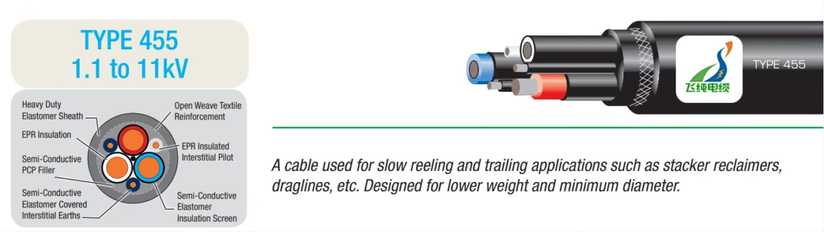
Engineering Overview: TYPE 455 mining cables represent an optimized category of Class 2 heavy-duty elastomer-sheathed cables specifically engineered for applications demanding minimal cable diameter and reduced weight per meter while maintaining comprehensive electrical protection. Manufactured in strict accordance with AS/NZS 2802:2000 standards, these cables are designed for voltage ratings from 1.1 kilovolts to 11 kilovolts, with a construction philosophy emphasizing reduced insulation thickness and elimination of cradle separators to achieve lower overall mass and diameter. The incorporation of two earth conductors and one pilot conductor positioned in outer interstices, combined with EPR insulation and semiconductive screening systems, makes these cables particularly well-suited for stacker reclaimer installations, dragline operations, and other slow reeling applications where cable weight directly impacts equipment performance and operational efficiency. The design represents a strategic balance between electrical performance requirements and mechanical handling considerations, offering mining operations a purpose-built solution for specific application scenarios where traditional heavier cable constructions would impose unacceptable operational constraints.
1. Introduction to TYPE 455 Cable Engineering
Mining operations worldwide increasingly demand electrical infrastructure solutions that balance competing requirements for electrical performance, mechanical durability, and operational efficiency. The AS/NZS 2802:2000 standard establishes comprehensive requirements for two distinct classes of multicore elastomer insulated and sheathed flexible reeling and trailing cables designed for surface mining, underground mining operations excluding coal mining, and general industrial applications requiring mobile plant electrical supply at system voltages from 1.1 kilovolts up to 33 kilovolts. Within this standard framework, TYPE 455 cables occupy a specialized position as Class 2 cables featuring semiconductive screening systems essential for medium voltage applications while incorporating design optimizations specifically targeting applications where cable weight and diameter present critical operational constraints.1
The fundamental distinction separating TYPE 455 cables from other AS/NZS 2802:2000 cable types lies in their construction philosophy. While TYPE 450 cables employ extra heavy-duty sheaths, composite copper polyester insulation screens, and open weave textile reinforcement optimized for maximum mechanical protection, TYPE 455 cables achieve reduced dimensions through elimination of cradle separators, utilization of thinner insulation profiles within AS/NZS 2802:2000 allowable limits, and deployment of simplified earth and pilot conductor arrangements. This design approach produces cables with notably lower weight per meter ratios and reduced overall diameters compared to TYPE 450 equivalents, making TYPE 455 cables particularly advantageous for equipment installations where cable mass represents a significant fraction of total system weight or where dimensional constraints limit cable routing options.2
The voltage range specification from 1.1 kilovolts to 11 kilovolts reflects practical operational requirements in mining and heavy industrial applications. The TYPE 455.3 designation indicates cables rated for 3.3 kilovolt service with corresponding test voltages of 12 kilovolts, while TYPE 455.6 cables serve 6.6 kilovolt applications with 22 kilovolt test voltages, and TYPE 455.11 cables address 11 kilovolt requirements with 30 kilovolt test voltages. This voltage progression enables mining operations to select cable specifications precisely matched to their electrical distribution system requirements, optimizing both electrical performance and cost considerations across their equipment fleet.
2. Primary Applications and Operational Scenarios
2.1 Stacker Reclaimer Systems: Engineering Context
Stacker reclaimers constitute essential infrastructure components in bulk material handling operations, serving critical functions in mining operations, power generation facilities, port terminals, and industrial processing plants. These large-scale machines perform dual functions of systematic stockpile formation through controlled material stacking and subsequent material recovery through reclaiming operations, enabling efficient storage and retrieval of bulk materials including coal, iron ore, limestone, aggregates, and various industrial minerals. The operational characteristics of stacker reclaimers create specific cable requirements that differentiate them from other mining equipment applications.3
Bucket wheel stacker reclaimers, representing the most common configuration in mining applications, feature rotating bucket wheels mounted on extendable booms capable of movement in three dimensional space through horizontal travel along rails, vertical luffing of the boom assembly, and rotational slewing of the superstructure. This complex movement pattern requires electrical power delivery through trailing cables capable of accommodating continuous repositioning cycles while maintaining electrical integrity throughout extended operational periods. The power requirements for these machines typically range from 500 kilowatts to 3000 kilowatts depending on machine capacity and design specifications, with voltage levels commonly specified at 3.3 kilovolts or 6.6 kilovolts to optimize power transmission efficiency while maintaining acceptable cable conductor sizes.
The slow reeling characteristic of stacker reclaimer operations differentiates these applications from high-speed reeling scenarios encountered in other mining equipment. Stacker reclaimers typically operate with controlled, deliberate movements synchronized with material handling requirements, creating cable stress profiles dominated by static loading and gradual position changes rather than rapid acceleration and deceleration cycles. This operational mode enables utilization of TYPE 455 cables with their optimized weight and diameter characteristics, as the mechanical demands of slow reeling applications do not require the enhanced mechanical protection inherent in heavier cable constructions.
Portal and bridge type stacker reclaimers present additional considerations for cable applications. These configurations feature structural frameworks that span stockpile areas, with bucket wheels or scraper systems positioned on mobile carriages traveling within the portal or bridge structure. The cable routing in these applications often involves extended horizontal runs combined with vertical drops, creating loading conditions that benefit from TYPE 455 cables’ reduced weight characteristics. Lower cable mass reduces static loading on cable support systems and enables use of lighter-weight support infrastructure, contributing to overall system cost optimization.
2.2 Dragline Excavator Applications
Dragline excavators represent another primary application domain for TYPE 455 cables, particularly in surface mining operations where these massive machines perform overburden removal and material handling functions. Walking draglines, characterized by bucket capacities ranging from 30 cubic meters to over 100 cubic meters and boom lengths extending beyond 100 meters, rank among the largest mobile land-based machines in existence. The electrical power requirements for these machines typically range from 4000 kilowatts to 10000 kilowatts, necessitating electrical distribution systems capable of delivering this substantial power through cables that must accommodate the dragline’s complex movement patterns.4
The operational cycle of dragline excavators creates distinctive cable stress patterns. The swinging motion of the superstructure as the machine positions its bucket for material handling creates rotational forces on trailing cables, while the walking motion employed to reposition the dragline between work areas introduces additional mechanical stresses. TYPE 455 cables address these operational demands through their flexible construction and optimized weight characteristics, as reduced cable mass minimizes the inertial forces generated during dragline movements and reduces the static loading imposed on cable support systems during extended operational periods.
Electrical distribution architecture for dragline operations typically employs high voltage systems to minimize conductor sizes and cable weights while maintaining efficient power transmission across the extended distances characteristic of surface mining operations. Voltage levels of 6.6 kilovolts and 11 kilovolts represent common specifications, with TYPE 455.6 and TYPE 455.11 cables providing purpose-built solutions optimized for these voltage requirements. The reduced diameter characteristics of TYPE 455 cables facilitate cable management on dragline installations, where space constraints and weight limitations influence both initial equipment design and operational cable handling procedures.
2.3 Slow Reeling Applications: Technical Considerations
The concept of slow reeling encompasses operational scenarios where cable deployment and retrieval occur at controlled rates synchronized with equipment positioning requirements rather than high-speed cycling characteristic of certain mining equipment. Slow reeling applications typically involve cable movement velocities below 1 meter per second, with positioning cycles measured in minutes rather than seconds. This operational mode creates cable stress profiles dominated by static and quasi-static loading conditions, with mechanical fatigue considerations related to flexing cycles rather than dynamic impact or rapid acceleration effects.
Equipment installations benefiting from TYPE 455 cables’ slow reeling optimization include mobile crushing plants, where positioning cycles occur on timescales of days or weeks; conveyor drive systems requiring periodic repositioning to accommodate changing material flow patterns; and various material handling equipment operating in controlled industrial environments. The common characteristic linking these applications involves substantial electrical power requirements delivered through cables experiencing infrequent but predictable movement cycles, where cable weight optimization provides operational benefits without compromising electrical or mechanical performance requirements.
The engineering analysis supporting TYPE 455 cable specification for slow reeling applications requires evaluation of multiple parameters. Cable weight calculations must account for total installed length and vertical lift requirements, as reduced cable mass directly translates to lower energy requirements for cable handling systems and reduced structural loading on equipment positioning mechanisms. Diameter optimization enables use of smaller drum assemblies for cable storage and reduces spatial requirements for cable routing through equipment frameworks. The balance between these mechanical optimization factors and electrical performance requirements defines the engineering design space within which TYPE 455 cables provide optimal solutions.
3. Material Construction and Technical Architecture
3.1 Conductor System Engineering
The conductor system in TYPE 455 cables employs three-phase flexible stranded tinned annealed copper conductors configured to deliver electrical power at medium voltage levels while maintaining the flexibility essential for reeling and trailing applications. The tinning process involves electrolytic or hot-dip application of tin coating to individual copper strands prior to stranding operations, providing multiple functional benefits. Tin coating creates a protective barrier against copper oxidation, particularly important in mining environments characterized by elevated humidity and exposure to sulfur-bearing gases that accelerate copper corrosion. The tin layer additionally facilitates soldering operations during cable termination procedures and improves inter-strand contact characteristics throughout the conductor’s service life.
Conductor stranding patterns follow carefully engineered specifications optimizing the relationship between electrical conductivity and mechanical flexibility. The stranding factor, defined as the ratio of actual conductor length to straight-line conductor length, typically ranges from 1.02 to 1.08 depending on conductor size and stranding configuration. This parameter directly influences both conductor resistance, which increases with stranding factor due to increased current path length, and conductor flexibility, which improves with higher stranding factors as individual strands follow shorter bending radii during cable flexing. TYPE 455 cables employ stranding configurations that prioritize flexibility while maintaining electrical performance within AS/NZS 2802:2000 specified limits.
3.2 EPR Insulation System Technology
Ethylene Propylene Rubber insulation technology represents current state-of-the-art for mining cable applications, offering superior performance across multiple parameters critical for reliable operation in demanding environments. EPR compounds consist of ethylene propylene diene monomer (EPDM) formulations incorporating carbon black for mechanical reinforcement, mineral fillers for electrical property optimization, antioxidants for thermal aging resistance, and crosslinking agents enabling formation of three-dimensional molecular networks during vulcanization processes. The resulting material exhibits exceptional dielectric strength, mechanical flexibility, and environmental resistance characteristics.5
The electrical properties of EPR insulation include dielectric strength exceeding 25 kilovolts per millimeter when measured according to AS/NZS 1660 test methods, volume resistivity greater than 10^14 ohm-centimeters ensuring minimal leakage current through insulation thickness, and dielectric constant in the range of 2.3 to 2.5 providing favorable capacitance characteristics for medium voltage cable applications. The dielectric loss tangent remains below 0.005 across the operational temperature range, minimizing dielectric heating effects that could accelerate thermal aging processes in high-voltage applications.
Mechanical properties include tensile strength exceeding 10 megapascals providing resistance to mechanical damage during installation and operation, ultimate elongation greater than 300 percent enabling accommodation of substantial deformation without structural failure, and tear resistance superior to alternative insulation materials reducing vulnerability to damage propagation from minor surface defects. The compression set characteristics, measured as permanent deformation remaining after removal of compressive loading, remain below 20 percent after 70 hours at 100°C, ensuring that insulation maintains its dimensional integrity throughout extended service periods.
Environmental resistance characteristics distinguish EPR from alternative insulation materials. Ozone resistance testing per AS/NZS standards demonstrates no visible cracking after 96 hours exposure to 50 parts per hundred million ozone concentration at 40°C, while accelerated aging tests indicate maintenance of electrical and mechanical properties after thermal exposure equivalent to decades of operational service. Chemical resistance encompasses immunity to mineral oils, hydraulic fluids, and common mining chemicals at ambient temperatures, with degradation resistance to moisture ingress superior to hygroscopic insulation materials.
3.3 Semiconductive Screening and Stress Control
Semiconductive components in TYPE 455 cable construction serve critical functions in electrical stress management and operational reliability enhancement. The conductor screen, applied directly over the conductor surface through extrusion processes, consists of elastomer compounds incorporating conductive carbon black at concentrations producing resistivity values in the range of 10 to 200 ohm-meters. This semiconductive layer eliminates air gaps between conductor strands and primary insulation, preventing formation of localized high-field regions that could initiate partial discharge phenomena and eventual insulation degradation.
The insulation screen, positioned between EPR insulation and cable outer layers, provides smooth, conductive surface ensuring uniform electric field distribution at the insulation boundary. This screen additionally facilitates electrical testing procedures by providing defined measurement points for insulation resistance and high-voltage testing protocols. The resistivity specifications for insulation screens typically match conductor screen requirements, ensuring equivalent stress control performance at both insulation boundaries.
The semiconducintelastomer covering on interstitial earth conductors provides both electrical and mechanical functions. The semiconductive properties enable uniform potential distribution along earth conductor surfaces, reducing field stress concentrations at conductor strand interstices. The elastomer base material provides mechanical protection against abrasion and impact damage while maintaining flexibility characteristics compatible with overall cable construction requirements. This dual-function design eliminates need for separate protective coverings, contributing to TYPE 455 cables’ diameter and weight optimization objectives.
3.4 PCP Filler and Structural Components
Polychloroprene (PCP) filler material occupies interstitial spaces within the cable core assembly, providing multiple functions essential for cable performance. The primary function involves maintenance of cable geometric integrity throughout flexing cycles and under mechanical loading conditions. PCP filler prevents conductor migration and maintains consistent spacing between cable components, ensuring that electrical performance parameters remain stable throughout the cable’s service life. The material selection for this application balances mechanical properties including compression resistance and flexibility with chemical resistance and thermal stability requirements.
The elimination of traditional cradle separators in TYPE 455 construction represents a significant departure from conventional mining cable design approaches. Cradle separators, employed in heavier cable constructions, provide mechanical support distributing compressive forces across the cable core assembly. TYPE 455 cables achieve equivalent functionality through optimized filler geometry and material selection, maintaining structural integrity while achieving diameter reduction objectives. This design approach requires careful analysis of mechanical stress distributions under operational loading conditions to ensure adequate performance throughout the cable’s service life.
3.5 Earth and Pilot Conductor Configuration
The interstitial earth conductor system in TYPE 455 cables consists of two separate earth conductors positioned in outer interstices between main power conductors. This configuration provides redundant grounding paths essential for mining safety requirements while contributing to cable diameter optimization. Each earth conductor employs flexible stranded tinned copper construction with CSP (Chlorosulfonated Polyethylene) covering providing chemical resistance and mechanical protection. The earth conductor sizing, specified in the technical tables, balances electrical conductivity requirements for fault current conduction with mechanical flexibility and overall cable diameter considerations.
The pilot conductor, also positioned in an outer interstice, features EPR insulation providing electrical isolation equivalent to main power conductors. This conductor serves control and monitoring functions in equipment installations, carrying signals for equipment positioning systems, operational monitoring circuits, and communication links. The pilot conductor cross-sectional area ranges from 8.48 square millimeters for smaller cable types to 39.49 square millimeters for larger variants, with sizing determined by signal transmission requirements and mechanical considerations. The EPR insulation thickness, typically matching main conductor insulation proportionately, ensures adequate electrical performance for pilot conductor applications.
3.6 Heavy Duty Elastomer Sheath System
The outer sheath system in TYPE 455 cables employs heavy-duty elastomer compounds, typically polychloroprene or chlorosulfonated polyethylene formulations optimized for mining applications. While designated as heavy-duty rather than extra heavy-duty as employed in TYPE 450 cables, the sheath thickness ranges from 4.5 millimeters to 6.9 millimeters depending on cable size provide substantial protection against environmental and mechanical challenges. This sheath thickness specification reflects TYPE 455 cables’ optimization for applications where extreme mechanical abuse is not anticipated but where comprehensive environmental protection remains essential.
Sheath compound formulations incorporate additives providing flame retardance conforming to AS/NZS standards, ozone resistance ensuring long-term stability under atmospheric exposure, ultraviolet stabilization for outdoor applications, and oil resistance addressing exposure to hydraulic fluids and lubricants in mining environments. The resulting material exhibits superior performance across environmental exposure scenarios typical of mining operations while maintaining flexibility characteristics essential for reeling applications.
4. Technical Specifications and Performance Parameters
| Part Number | Voltage Rating | Conductor Size (mm²) | Conductor Diameter (mm) | Pilot Size (mm²) | Pilot Diameter (mm) | Sheath Thickness (mm) | Cable Diameter (mm) | Weight (kg/100m) |
|---|---|---|---|---|---|---|---|---|
| MCO-455.3-025 | 3.3kV | 25 | 13.1 | 8.48 | 6.6 | 4.5 | 42.33 | 284 |
| MCO-455.3-035 | 3.3kV | 35 | 14.3 | 8.48 | 6.6 | 4.8 | 45.87 | 343 |
| MCO-455.3-050 | 3.3kV | 50 | 16.3 | 12.51 | 7.4 | 5.2 | 51.57 | 422 |
| MCO-455.3-070 | 3.3kV | 70 | 17.9 | 19.04 | 8.5 | 5.7 | 56.44 | 549 |
| MCO-455.3-095 | 3.3kV | 95 | 19.7 | 24.68 | 9.3 | 6.1 | 61.47 | 647 |
| MCO-455.3-120 | 3.3kV | 120 | 21.3 | 29.62 | 10.3 | 6.4 | 65.49 | 784 |
| MCO-455.3-150 | 3.3kV | 150 | 23.0 | 39.15 | 11.4 | 6.5 | 69.91 | 941 |
| Part Number | Voltage Rating | Conductor Size (mm²) | Conductor Diameter (mm) | Pilot Size (mm²) | Pilot Diameter (mm) | Sheath Thickness (mm) | Cable Diameter (mm) | Weight (kg/100m) |
|---|---|---|---|---|---|---|---|---|
| MCO-455.6-025 | 6.6kV | 25 | 14.7 | 8.48 | 6.6 | 5.0 | 47.05 | 316 |
| MCO-455.6-035 | 6.6kV | 35 | 15.9 | 8.48 | 7.0 | 5.3 | 50.60 | 382 |
| MCO-455.6-050 | 6.6kV | 50 | 17.5 | 12.51 | 7.8 | 5.6 | 55.12 | 461 |
| MCO-455.6-070 | 6.6kV | 70 | 19.1 | 19.04 | 8.9 | 6.0 | 59.98 | 588 |
| MCO-455.6-095 | 6.6kV | 95 | 20.9 | 24.68 | 9.7 | 6.3 | 64.55 | 679 |
| MCO-455.6-120 | 6.6kV | 120 | 22.5 | 29.62 | 10.7 | 6.5 | 68.57 | 824 |
| MCO-455.6-150 | 6.6kV | 150 | 24.2 | 39.49 | 11.8 | 6.6 | 72.77 | 975 |
| Part Number | Voltage Rating | Conductor Size (mm²) | Conductor Diameter (mm) | Pilot Size (mm²) | Pilot Diameter (mm) | Sheath Thickness (mm) | Cable Diameter (mm) | Weight (kg/100m) |
|---|---|---|---|---|---|---|---|---|
| MCO-455.11-025 | 11kV | 25 | 18.7 | 8.48 | 7.8 | 6.1 | 59.10 | 451 |
| MCO-455.11-035 | 11kV | 35 | 19.9 | 8.48 | 7.8 | 6.3 | 62.18 | 505 |
| MCO-455.11-050 | 11kV | 50 | 21.5 | 12.51 | 8.6 | 6.4 | 66.01 | 583 |
| MCO-455.11-070 | 11kV | 70 | 23.1 | 19.04 | 9.7 | 6.5 | 70.18 | 716 |
| MCO-455.11-095 | 11kV | 95 | 24.9 | 24.68 | 10.5 | 6.7 | 74.75 | 814 |
| MCO-455.11-120 | 11kV | 120 | 26.5 | 29.62 | 11.5 | 6.8 | 79.00 | 971 |
| MCO-455.11-150 | 11kV | 150 | 28.2 | 39.49 | 12.6 | 6.9 | 83.19 | 1127 |
4.1 Comparative Analysis: TYPE 455 vs TYPE 450 Cables
Weight and Diameter Comparison (95mm² Conductor at 3.3kV)
TYPE 450.3-095
Overall Diameter: 68.72 mm
Weight: 709 kg/100m
Sheath Thickness: 6.3 mm (Extra Heavy Duty)
Construction: Cradle separator, composite copper/polyester screen, textile reinforcement
Weight Efficiency: 7.46 kg per mm² conductor
TYPE 455.3-095
Overall Diameter: 61.47 mm (10.5% reduction)
Weight: 647 kg/100m (8.7% reduction)
Sheath Thickness: 6.1 mm (Heavy Duty)
Construction: No cradle, simplified earth/pilot arrangement, PCP filler
Weight Efficiency: 6.81 kg per mm² conductor
Engineering Significance: The 8.7 percent weight reduction achieved by TYPE 455 cables translates to meaningful operational benefits in applications where cable mass represents significant fraction of system weight. For a typical 500-meter stacker reclaimer installation, this weight differential amounts to approximately 310 kilograms of saved mass, reducing structural loading requirements and energy consumption for cable handling systems. The 10.5 percent diameter reduction enables use of smaller cable drums and reduces spatial requirements for cable routing, providing additional installation and operational advantages.
4.2 Electrical Performance Characteristics
Current-carrying capacity calculations for TYPE 455 cables must account for installation conditions, ambient temperature parameters, and grouping factors affecting heat dissipation characteristics. For cables installed in free air with adequate ventilation at ambient temperature of 30 degrees Celsius, approximate continuous current ratings include 165 to 180 amperes for 25 square millimeter conductors, 200 to 220 amperes for 35 square millimeter conductors, 245 to 270 amperes for 50 square millimeter conductors, 305 to 335 amperes for 70 square millimeter conductors, 370 to 410 amperes for 95 square millimeter conductors, 435 to 480 amperes for 120 square millimeter conductors, and 500 to 550 amperes for 150 square millimeter conductors.6
Voltage drop calculations require consideration of both resistive and reactive components of conductor impedance. At power factor 0.8 lagging, typical of induction motor loads prevalent in mining applications, voltage drop per ampere per kilometer ranges from approximately 1.1 volts for 150 square millimeter conductors to 2.9 volts for 25 square millimeter conductors. Mining operations typically limit voltage drop to 3 to 5 percent of supply voltage to ensure adequate motor starting performance and prevent excessive heating in equipment windings. For a 6.6 kilovolt system with 5 percent voltage drop allowance (330 volts), a 95 square millimeter conductor carrying 350 amperes would be limited to approximately 550 meters cable length at 0.8 power factor.
5. Standards Compliance and Regulatory Framework
5.1 AS/NZS 2802:2000 Requirements
The AS/NZS 2802:2000 standard establishes comprehensive requirements governing design, construction, testing, and performance specifications for reeling and trailing cables employed in mining and industrial applications. This joint Australian and New Zealand standard reflects decades of operational experience and represents consensus requirements developed through collaboration between mining operators, cable manufacturers, regulatory authorities, and technical experts. TYPE 455 cables must demonstrate compliance with all applicable standard requirements through combination of design verification, type testing, and routine production testing protocols.7
Construction requirements specified in AS/NZS 2802:2000 mandate specific material selections and dimensional parameters. Conductor materials must conform to AS/NZS 1125 requirements for flexible stranded tinned copper conductors, with stranding patterns and resistance values meeting specified tolerances. Insulation materials require compliance with AS/NZS 3808 specifications for EPR compounds, including minimum electrical, mechanical, and thermal performance parameters. Semiconductive materials must exhibit resistivity values within specified ranges to ensure effective stress control performance. Sheath materials must satisfy requirements for oil resistance, flame retardance, and mechanical properties as defined in referenced standards.
5.2 Testing Protocols and Quality Assurance
Type testing requirements for TYPE 455 cables encompass comprehensive evaluation protocols verifying compliance with AS/NZS 2802:2000 performance specifications. High-voltage withstand testing subjects cable samples to test voltages substantially exceeding operational voltage levels: 12 kilovolts for TYPE 455.3 cables, 22 kilovolts for TYPE 455.6 cables, and 30 kilovolts for TYPE 455.11 cables. Testing duration of five minutes at specified voltage verifies insulation system integrity and screening effectiveness under electrical stress conditions exceeding normal operational levels.
Mechanical testing protocols evaluate cable performance under conditions simulating operational stresses. Bending tests subject cable samples to repeated flexing cycles around mandrels sized according to standard specifications, verifying that cable construction maintains electrical integrity throughout flexing sequences representing years of operational service. Tensile testing evaluates cable resistance to pulling forces during installation and operation, with pass criteria requiring maintenance of electrical and mechanical properties after application of specified tensile loads. Flame propagation testing verifies that cable sheath materials resist flame spread, an essential safety characteristic for mining applications.
Routine production testing performed on every cable length manufactured includes conductor resistance measurement verifying proper conductor sizing and material quality, high-voltage testing at reduced voltage levels identifying manufacturing defects, and visual inspection confirming proper marking and absence of visible defects. Quality assurance systems require manufacturers to maintain comprehensive testing records, implement statistical process control monitoring production consistency, and provide certification documentation accompanying each cable delivery.
5.3 Comparison with VDE 0250 Part 812 Standards
The German standard VDE 0250 Part 812 represents an alternative regulatory framework for flexible cables employed in power installations, including mining applications. Understanding distinctions between AS/NZS 2802:2000 and VDE 0250 Part 812 standards proves essential for engineering personnel specifying cables for international mining projects or evaluating cable performance across different regulatory environments. While both standards address similar application requirements, their technical approaches and specific requirements reflect different design philosophies and regulatory environments.8
AS/NZS 2802:2000 TYPE 455 Approach
Voltage Range: 1.1kV to 11kV for TYPE 455 variants (up to 33kV for extended TYPE 455 series)
Insulation Technology: EPR with semiconductive screens for medium voltage applications
Construction Philosophy: Optimized weight and diameter for specific applications, particularly stacker reclaimers
Testing Requirements: Comprehensive type testing including bending followed by partial discharge testing
Application Focus: Surface mining, hard rock underground mining, industrial material handling
Regional Context: Australian and New Zealand mining conditions with specific environmental parameters
VDE 0250 Part 812 Approach
Voltage Range: Up to 450/750V for low voltage industrial applications
Insulation Technology: EPR or polychloroprene for low voltage service, screening generally not required
Construction Philosophy: Robust construction for harsh industrial environments, emphasis on mechanical protection
Testing Requirements: Voltage withstand, mechanical properties, flame retardance per VDE specifications
Application Focus: Fixed installations, motor connections, control circuits in industrial settings
Regional Context: European industrial applications with different regulatory framework
The fundamental distinction between these standards resides in their voltage classifications and intended application domains. VDE 0250 Part 812 addresses low voltage applications up to 450/750 volts, serving requirements for auxiliary equipment connections, lighting circuits, and small motor power supplies. AS/NZS 2802:2000 TYPE 455 cables operate at medium voltage levels from 1.1 kilovolts to 11 kilovolts, powering large mobile mining equipment requiring substantial power delivery through optimized cable designs. The construction differences reflect these distinct voltage requirements, with VDE cables omitting semiconductive screening systems essential for reliable medium voltage operation.
Both standards emphasize mechanical durability and environmental resistance appropriate for demanding industrial applications, but they address different segments of industrial electrical infrastructure. Mining operations frequently employ cables meeting both standards in complementary roles, with TYPE 455 cables powering major equipment and VDE 0250 Part 812 cables serving auxiliary systems, control circuits, and fixed installation requirements. The selection between standards depends on specific application voltage requirements, regulatory jurisdiction, and operational conditions rather than any inherent superiority of one standard over another.
6. Safety Thresholds and Operational Parameters
6.1 Thermal Management Requirements
Thermal management considerations for TYPE 455 cables encompass multiple parameters affecting both cable longevity and operational safety. The maximum continuous conductor temperature of 90 degrees Celsius represents the thermal limit for normal operation, determined by EPR insulation material properties and long-term aging characteristics. Extended operation at temperatures approaching this limit accelerates chemical aging processes in insulation materials, progressively reducing dielectric strength and mechanical properties. Mining operations should implement loading practices maintaining conductor temperatures substantially below maximum ratings during normal operation, reserving higher temperature operation for short-duration overload conditions.
Short-term overload conditions permit conductor temperatures up to 130 degrees Celsius for cumulative durations not exceeding 100 hours annually, with individual overload events limited to five hours maximum duration. These emergency ratings accommodate motor starting transients and temporary equipment overloads without requiring immediate cable replacement, provided that cumulative thermal stress remains within specified limits. The temperature differential between continuous and emergency ratings reflects the time-dependent nature of thermal aging processes, where brief high-temperature excursions produce minimal degradation compared to sustained operation at elevated temperatures.
⚠ Critical Thermal Operating Parameters:
Maximum Continuous Temperature: 90°C conductor temperature must not be exceeded during normal operations. Implementation of temperature monitoring systems with alarm setpoints at 85°C provides adequate safety margin.
Ambient Temperature Range: Operating environment must remain between -25°C and +90°C. Installation in environments approaching these extremes requires detailed thermal analysis and potentially derating of current-carrying capacity.
Short Circuit Temperature: Maximum conductor temperature during short circuit conditions limited to 250°C for duration not exceeding 1 second. Protection systems must clear faults within this time limit to prevent cable damage.
Installation Temperature: Cable installation procedures should not be attempted when cable temperature falls below -5°C, as reduced flexibility at low temperatures increases risk of mechanical damage during handling.
6.2 Mechanical Stress Limitations
Mechanical stress management proves equally critical for TYPE 455 cable reliability in reeling and trailing applications. The minimum bending radius during installation and operation must be maintained at 12 times cable diameter for single bends encountered during installation and 15 times cable diameter for repeated flexing in reeling service. For a TYPE 455.11-095 cable with 74.75 millimeter diameter, these requirements translate to minimum bending radii of 897 millimeters for installation bends and 1,121 millimeters for reeling operations. Violations of minimum bending radius specifications create localized stress concentrations that accelerate mechanical fatigue processes and may damage internal cable components including conductor strands and screening layers.
Tensile loading during installation and operation must not exceed 50 newtons per square millimeter of total conductor cross-sectional area. This limitation prevents overstressing of conductor strands and screening components that could lead to strand breakage or screening system damage. For TYPE 455 cables with three 95 square millimeter conductors plus earth and pilot conductors, maximum tensile load calculates to approximately 14,250 newtons or 1,450 kilograms force for main conductors. Installation procedures should incorporate pulling force monitoring to ensure compliance with these limits, particularly for long cable runs or complex routing configurations where friction forces may accumulate.
6.3 Environmental Operating Envelope
Environmental conditions significantly influence TYPE 455 cable performance and must be maintained within specified limits for reliable long-term operation. Humidity exposure up to 95 percent relative humidity proves acceptable for properly installed cables with intact outer sheaths, but prolonged exposure to saturated environments or direct water immersion may compromise performance if moisture penetrates sheath system through mechanical damage or inadequate termination sealing. Regular inspection protocols should monitor cable installations for water ingress evidence, with corrective actions implemented immediately upon detection of moisture infiltration.
Chemical exposure resistance depends on specific contaminant identity and concentration. Elastomer sheath materials provide excellent resistance to mineral oils, hydraulic fluids, and common mining chemicals at ambient temperatures. However, concentrated acids with pH below 3, strong alkalies with pH above 11, and certain organic solvents including ketones and aromatic hydrocarbons may attack sheath materials, requiring additional mechanical protection or alternative sheath formulations for specific applications. Material compatibility testing should be conducted for applications involving unusual chemical exposures to verify adequate resistance characteristics.9
7. Installation Procedures and Operational Guidelines
7.1 Pre-Installation Planning
Successful TYPE 455 cable installation requires comprehensive planning addressing electrical, mechanical, and environmental considerations. Electrical load analysis must determine steady-state current requirements, motor starting current magnitudes and durations, and duty cycle characteristics to ensure proper conductor sizing. Cable routing planning should minimize exposure to mechanical hazards while maintaining adequate bending radii throughout the route and providing accessibility for inspection and maintenance activities. Environmental assessment must document ambient temperature ranges, humidity levels, chemical exposure potential, and ultraviolet exposure in outdoor installations to verify compatibility with cable specifications.
Reeling system design requires particular attention for applications involving TYPE 455 cables’ optimized weight and diameter characteristics. Drum diameter must accommodate minimum bending radius requirements with adequate safety margin, typically specifying drum diameters at least 20 times cable diameter for optimal service life. For TYPE 455.6-095 cables with 64.55 millimeter diameter, minimum drum diameter calculates to 1,291 millimeters. Cable guiding systems must prevent uneven winding or cable pileup that could damage cable structure during reeling operations, while tension control systems should maintain appropriate cable tension throughout deployment and retrieval cycles.
7.2 Installation Best Practices
✓ Critical Installation Requirements:
Minimum Bending Radius Maintenance: Utilize cable guides, rollers, and support structures maintaining bending radii exceeding 15 times cable diameter throughout installation route. Document all permanent bends with radius measurements for future reference.
Pulling Force Monitoring: Employ dynamometers or tension meters monitoring pulling forces during installation, ensuring forces remain below 50 N/mm² conductor area limit. Install intermediate pulling points for long runs where calculated forces approach limits.
Support Spacing Optimization: Position cable supports at intervals of 2 to 4 meters depending on cable size and configuration, preventing excessive sag while maintaining flexibility for trailing applications.
Termination Quality Assurance: Utilize only termination kits and connectors rated for cable voltage and current levels, following manufacturer installation procedures precisely. Perform electrical testing of all terminations before commissioning.
Documentation Completeness: Maintain detailed installation records including cable routing diagrams, installation date, test results, and maintenance history for entire cable service life.
7.3 Critical Operational Precautions
⚠ Mandatory Safety Prohibitions:
Underground Coal Mining Restriction: TYPE 455 cables are NOT certified for underground coal mining operations due to specific explosion hazard requirements. Underground coal mining requires cables meeting additional standards for explosive atmosphere service and flame propagation resistance.
Continuous Submersion Prohibition: While cables resist moisture and surface water exposure, they are not designed for continuous submersion in water or other liquids. Submersion applications require specialized submersible cable constructions.
Chemical Compatibility Verification: Never expose cables to concentrated acids, strong alkalies, or incompatible solvents without prior material compatibility verification. Consult manufacturer chemical resistance documentation for specific chemical exposure scenarios.
Overloading Prevention: Never exceed cable rated current capacity for extended periods. Implement current monitoring systems with alarm and protection functions preventing sustained overload conditions.
Mechanical Abuse Avoidance: Train equipment operators in proper cable handling techniques, avoiding contact with sharp objects, excessive tension during equipment movement, and violation of minimum bending radius specifications.
8. Maintenance Protocols and Troubleshooting
8.1 Preventive Maintenance Program
Comprehensive preventive maintenance programs for TYPE 455 cables should incorporate regular visual inspections, periodic electrical testing, and systematic documentation of cable condition throughout service life. Visual inspection frequency depends on operational severity, with monthly inspections appropriate for normal service conditions and weekly inspections warranted for severe applications. Inspection protocols should systematically examine cable length for sheath surface condition noting cuts, abrasions, discoloration, or material degradation, cable routing configuration identifying deviations from proper installation, presence of contamination including oil, grease, or chemical exposure, and evidence of thermal damage including discoloration or material softening.
Electrical testing programs provide essential information about cable condition undetectable through visual inspection alone. Insulation resistance testing performed annually at minimum employs megohmmeters applying test voltages of 1,000 volts DC for low voltage circuits and 2,500 volts DC for medium voltage applications. Test results should be compared to baseline measurements obtained during cable commissioning and manufacturer specifications to identify degradation trends indicating approaching end-of-service-life conditions. Trending analysis of insulation resistance measurements over time proves more valuable than single-point measurements, as progressive degradation indicates developing problems requiring investigation and potential corrective action.
8.2 Common Operational Issues and Solutions
Mechanical abrasion represents the most frequently encountered failure mode for TYPE 455 cables in mining service. Early-stage abrasion manifests as surface scuffing or discoloration of outer sheath, progressing through sheath thickness to expose internal cable components if not addressed. Prevention strategies include implementation of protective cable routing systems, installation of cable guides and supports at appropriate intervals, operator training emphasizing proper cable handling, and establishment of regular inspection protocols identifying early-stage damage. When abrasion damage is detected, affected cable sections should be evaluated to determine whether protective measures can arrest degradation or whether cable replacement is necessary.
Insulation resistance degradation can result from moisture ingress through damaged sheath areas, thermal stress from overloading or inadequate cooling, chemical attack from incompatible contaminants, or electrical stress from voltage transients. Early detection through periodic insulation resistance testing enables corrective action before complete insulation failure occurs. Troubleshooting procedures require comprehensive insulation resistance testing comparing results with baseline measurements and manufacturer specifications. If insulation resistance falls below acceptable levels, cable should be removed from service immediately pending detailed investigation identifying failure mechanism and implementing corrective measures preventing recurrence.
8.3 Failure Analysis and Documentation
When TYPE 455 cable failures occur, systematic failure analysis proves essential for preventing repeat failures and optimizing maintenance strategies. Failure analysis should include examination of failed cable section, analysis of operating conditions at failure time, review of maintenance records identifying contributing factors, and implementation of corrective actions addressing root causes. Common failure modes include mechanical damage from improper handling or installation, electrical failures due to moisture ingress or electrical stress, and thermal failures from overloading or poor ventilation. Each failure mode requires specific corrective actions that may include changes in installation procedures, operational practices, or maintenance protocols.
Contact Anhui Feichun Special Cable Co., Ltd.
Our engineering team provides comprehensive technical support for TYPE 455 mining cable specifications, application analysis, and custom cable solutions tailored to specific operational requirements.
安徽飞纯特种电缆有限公司
ISO 9001:2015 Certified Manufacturer
References and Technical Citations
- Standards Australia and Standards New Zealand. (2000). AS/NZS 2802:2000 Electric cables – Reeling and trailing – For mining and general use (other than underground coal mining). Retrieved from Standards Australia Store
- Caledonian Cables. (2020). AS/NZS 2802:2000 Reeling & Trailing Cables – Type 455 Technical Specifications. Mining Cables Technical Documentation. Retrieved from Caledonian Cable Technical Library
- Heyl & Patterson, Inc. (2024). Using Stacker Reclaimers In Bulk Material Handling. Retrieved from Heyl & Patterson Engineering Resources
- Reeling Cable Technical Resources. (2025). Mining Cable Reels and Trailing Cable Systems for Heavy Equipment. Retrieved from reelingcable.com
- Amplex Mining. (2025). Type 455 3.3kV Mining Cables in Shearer & Continuous Miner Applications. Retrieved from amplexmining.com.au
- Eland Cables. (2024). Type 450 and Type 455 Flexible Rubber Mining Cables – Technical Guide. Retrieved from Eland Cables Technical Library
- ANSI Standards Store. (2020). AS/NZS 2802:2000 (R2020) – Electric cables – Reeling and trailing – Complete Standard. Retrieved from ANSI Webstore
- VDE Verlag GmbH. (1985). DIN VDE 0250-812:1985-05 – Cables, wires and flexible cords for power installation. Retrieved from VDE Publishing House
- Tullyn Trading Pty Ltd. (2024). Type 455 Mining Power Cable 3.3 to 33kv – Construction and Applications. Retrieved from Tullyn Trading Technical Resources
Professional Disclaimer: This technical documentation is provided for engineering reference and informational purposes. While comprehensive efforts have been made to ensure technical accuracy, Anhui Feichun Special Cable Co., Ltd. recommends consultation with qualified electrical engineers and strict adherence to all applicable local codes, regulations, and standards for specific installations. Cable specifications and international standards are subject to periodic revision; users should verify current standard requirements for their specific applications. All electrical installations should be performed by qualified personnel in accordance with relevant safety standards and regulatory requirements.


