
Heavy Duty Elastomer Sheath EPR Insulation Trailing Cables for Mining Machinery
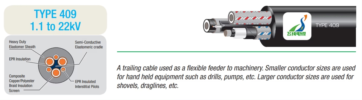
TYPE 409 1.1 to 22kV Mining Cables to AS/NZS 2802:2000
Manufactured by Anhui Feichun Special Cable Co., Ltd. (安徽飞纯特种电缆有限公司)
Executive Summary
TYPE 409 mining cables represent a specialized category of flexible trailing cables designed to meet the rigorous demands of surface mining, underground mining operations, and general industrial applications where movable plant requires reliable electrical power supply. Manufactured in compliance with the AS/NZS 2802:2000 standard, these Class 2 heavy-duty cables feature ethylene propylene rubber (EPR) insulation, composite copper and polyester braid screening, and elastomeric sheath construction. Available in voltage ratings from 1.1 kilovolts up to 22 kilovolts, TYPE 409 cables serve as the electrical lifeline for machinery ranging from handheld drills and pumps to massive dragline excavators and shovels.
The engineering sophistication of TYPE 409 cables reflects decades of development in mining cable technology, incorporating semiconductive screening systems, central cradle separators, and interstitial pilot conductors that work together to ensure safe and reliable operation in extreme environmental conditions. The cables must withstand extraordinary mechanical stresses, continuous flexing, abrasion from dust and debris, exposure to oils and chemicals, ultraviolet radiation, and temperature extremes while maintaining electrical integrity and personnel safety.
1. Purpose and Application of TYPE 409 Mining Cables
Primary Function: TYPE 409 cables serve as flexible feeder trailing cables providing mobile power supply to mining machinery and equipment. The designation “trailing cable” refers to the cable’s ability to follow or “trail” behind mobile equipment as it moves throughout the mining operation, continuously delivering electrical power while accommodating the complex movement patterns of the machinery.
1.1 Equipment Applications by Conductor Size
Small Conductor Sizes (6mm² to 50mm²)
The smaller conductor configurations within the TYPE 409 range are specifically engineered for handheld and portable equipment commonly used in mining operations. These applications typically involve frequent movement, tight working spaces, and the need for exceptional cable flexibility. Handheld rock drills, ranging from pneumatic to electric models, require cables that can withstand the continuous vibration and abrupt movements inherent to drilling operations. The cable must maintain electrical integrity despite being dragged across rough surfaces, subjected to impact from falling debris, and twisted as operators maneuver the equipment into position.
Portable pumps, essential for managing water ingress in underground mining operations, rely on smaller TYPE 409 cables for their power supply. These pumps may need rapid repositioning as water accumulation patterns change, requiring cables that combine flexibility with durability. Electric ventilation fans, crucial for maintaining air quality in confined mining spaces, similarly benefit from the balanced design of smaller TYPE 409 configurations.
Large Conductor Sizes (70mm² to 150mm²)
The larger conductor sizes address the enormous power requirements of the mining industry’s most substantial equipment. Dragline excavators, some of the largest mobile land machines ever constructed, represent perhaps the most demanding application for TYPE 409 cables. These colossal machines, capable of moving hundreds of tonnes of material with each bucket swing, require continuous power delivery at medium voltage levels. The trailing cable must support not only its own considerable weight but also withstand the dynamic forces generated during the dragging operation, which places extraordinary tensile loads on the cable structure.
Electric shovels and power shovels, commonly employed in open-cut mining operations, similarly require robust TYPE 409 cables in larger conductor sizes. These machines execute complex digging patterns that place the trailing cable under multidirectional stress as the shovel’s upper works rotate, the boom extends and retracts, and the entire machine relocates to new working positions. Bucket-wheel excavators, used extensively in coal mining, present another demanding application where continuous material removal creates constant cable movement and vibration.
1.2 Comparative Analysis: AS/NZS 2802:2000 vs VDE 0250-812
International Standards Context: While TYPE 409 cables comply with the Australian and New Zealand standard AS/NZS 2802:2000, it is valuable to understand how they compare with cables manufactured to the German standard VDE 0250 Part 812. This comparison provides insights into different international approaches to mining cable design and helps contextualize the TYPE 409 specification within the global mining industry.
| Specification Parameter | AS/NZS 2802:2000 TYPE 409 | VDE 0250-812 NSSHÖU | Key Differences |
|---|---|---|---|
| Voltage Rating | 1.1kV to 22kV (multiple voltage classes: 409.1, 409.3, 409.6, 409.11, 409.22) | Typically 0.6/1kV to 3.6/6kV | AS/NZS 2802 offers significantly higher voltage ratings, extending to 22kV for large dragline applications |
| Insulation Material | EPR (Ethylene Propylene Rubber) with semiconductive screens for MV applications | EPR with Type 3GI3 compound per DIN VDE 0207 Part 20 | Similar materials but different compound specifications and screening requirements |
| Sheath Construction | Heavy-duty elastomer (PCP/CPE/CSP) with specified thickness based on voltage | Synthetic elastomer Type 5GM3 per DIN VDE 0207 Part 21 | Both use elastomeric compounds but with different compound designations and testing standards |
| Screening System | Composite copper/polyester braid with semiconductive insulation screens | Semi-conductive layer with maximum resistivity 200 Ω×m | AS/NZS system emphasizes composite construction for mechanical reinforcement |
| Cradle Design | Semi-conductive elastomeric cradle separator for conductor support | Kevlar-reinforced center cradle in some configurations | VDE standard explicitly specifies Kevlar reinforcement for high-stress applications |
| Temperature Range | -25°C to +90°C continuous operation | -25°C to +90°C (mobile), -40°C to +80°C (fixed installation) | Similar operating ranges with VDE providing separate ratings for installation types |
| Pilot Conductors | EPR-insulated interstitial pilots (typically 0.75mm² to 1.25mm²) | Varies by cable type; some configurations include earth and pilot cores | AS/NZS consistently includes pilot conductors; VDE configurations vary more widely |
| Testing Standards | AS/NZS 1660 series for cable testing, AS 3007 for mining installations | DIN VDE testing protocols, flame tests per DIN VDE 0482 Part 265-2-1 | Different test methodologies reflecting regional regulatory requirements |
Standards comparison based on: AS/NZS 2802:2000 specification documentation[1] and DIN VDE 0250-812 technical requirements[2]
Analysis of Standard Differences
The primary distinction between AS/NZS 2802:2000 TYPE 409 and VDE 0250-812 cables lies in their voltage capability and screening sophistication. The AS/NZS standard was developed specifically to address the requirements of large-scale open-cut mining operations common in Australia, where dragline excavators and massive electric shovels operate at medium voltage levels up to 22 kilovolts. This voltage range enables efficient power transmission over the extended cable lengths required in these operations while minimizing conductor size and cable weight.
The VDE 0250-812 standard, while equally robust in its construction requirements, traditionally focuses on lower voltage applications more common in European underground mining and industrial settings. The explicit specification of Kevlar reinforcement in VDE cables for high-stress applications reflects the German engineering approach of using synthetic fiber strength members, whereas the AS/NZS standard achieves similar mechanical performance through composite screening systems and central cradle designs.
2. Technical Characteristics and Material Structure
2.1 Conductor System
The conductor assembly forms the foundation of TYPE 409 cable electrical performance and mechanical durability. The specification requires flexible stranded tinned annealed copper construction, a design choice that optimizes multiple critical properties. The stranding pattern distributes mechanical loads across numerous small-diameter wires rather than concentrating stress in a solid conductor, dramatically improving flex life and fatigue resistance. Conductor sizes range from 25 square millimeters for light-duty applications to 150 square millimeters for heavy dragline installations, with the specific number and diameter of individual strands engineered to balance electrical conductivity against mechanical flexibility.
The tinning process, whereby a thin layer of tin is applied to the copper strands, serves multiple protective functions crucial in mining environments. Tin provides a barrier against oxidation, particularly important in the dusty, chemically aggressive atmosphere of mining operations where sulfur compounds and other corrosive agents accelerate copper degradation. Additionally, the tin coating facilitates better electrical connection at terminations and improves the bond between the conductor and surrounding insulation materials.
Copper conductor specifications and tinning processes conform to international standards for electrical conductivity and corrosion resistance in harsh industrial environments[3]
2.2 Insulation System – EPR Technology
EPR (Ethylene Propylene Rubber) Insulation: The choice of EPR as the primary insulation material represents a sophisticated engineering decision based on the unique demands of mining cable applications. EPR belongs to the family of thermosetting elastomers, specifically cross-linked polymers that undergo irreversible chemical changes during vulcanization to create a three-dimensional molecular network.
Electrical Properties of EPR Insulation
EPR insulation demonstrates exceptional dielectric strength, typically exceeding 20 kV/mm, which provides substantial safety margin above the nominal voltage ratings of TYPE 409 cables. The volume resistivity of properly formulated EPR compounds reaches values greater than 10¹⁴ Ω×cm, ensuring minimal leakage current even in humid conditions. The dielectric constant of EPR ranges between 2.5 to 3.0 at power frequency, lower than many alternative insulation materials, which reduces capacitive effects and improves power factor in medium voltage applications.
The dissipation factor (tan δ) of EPR insulation typically measures less than 0.01 at 50Hz, indicating low dielectric losses and excellent electrical efficiency. This characteristic becomes particularly important in mining applications where cable lengths may extend hundreds of meters, and cumulative energy losses must be minimized. EPR’s corona resistance proves exceptional, with the material demonstrating stable performance under partial discharge conditions that would rapidly degrade alternative insulation types.
Mechanical and Environmental Properties
The mechanical properties of EPR insulation contribute significantly to TYPE 409 cable durability. Tensile strength typically exceeds 10 MPa, while elongation at break reaches 300% or greater, providing the material with exceptional ability to withstand stretching forces without failure. This combination of strength and elasticity proves crucial in dragline applications where cables experience substantial tensile loads.
EPR maintains flexibility across an extraordinary temperature range, from -25°C to +90°C for continuous operation, with short-term capability extending to +130°C. This thermal performance enables TYPE 409 cables to function reliably in Australian mining environments where surface temperatures may exceed 45°C while equipment operation generates additional heat. The low-temperature flexibility ensures reliable performance during cold winter mornings in elevated mine sites, maintaining cable handling characteristics and preventing brittle fracture.
Chemical resistance represents another critical EPR characteristic. The material demonstrates excellent resistance to ozone, a significant advantage in applications involving electrical arcing and corona discharge. Weathering resistance enables extended outdoor exposure without degradation, essential for surface mining applications. While EPR shows moderate oil resistance compared to specialized compounds, its formulation for TYPE 409 cables includes additives that improve resistance to hydraulic fluids, diesel fuel, and lubricating oils commonly encountered in mining equipment environments.
EPR insulation electrical and mechanical properties documented by industry standards and testing organizations[4][5]
2.3 Semiconductive Screening Systems
For TYPE 409 cables rated at 3.3 kilovolts and above, semiconductive screening layers surround both the conductor and the insulation outer surface. These screens serve critical functions in managing electrical stress distribution and enhancing safety. The conductor screen provides a smooth, uniform interface between the stranded conductor and the EPR insulation, eliminating air voids that could become sites for partial discharge inception. The semiconductive compound must maintain resistivity within a controlled range, typically 10 to 500 Ω×m, low enough to distribute electrical stress uniformly but high enough to avoid significant power loss.
The insulation screen creates a defined electrical boundary at the insulation outer surface, providing uniform electrical stress distribution and creating effective earth fault detection capability. Modern semiconductive compounds for TYPE 409 cables utilize specialized carbon black dispersions and elastomeric matrices that maintain their electrical properties across the cable’s temperature range and throughout its service life despite exposure to mechanical stress and environmental extremes.
2.4 Composite Screening and Earthing System
Composite Copper/Polyester Braid: One of the most sophisticated aspects of TYPE 409 cable design is the composite screening system that combines tinned annealed copper braiding interwoven with polyester yarn. This hybrid construction provides multiple benefits compared to conventional metallic tape or wire screening alone.
The copper braid component provides the essential electrical functions of the screen, including creating an earth fault current path with sufficient capacity to operate protective devices reliably, providing electromagnetic shielding to minimize interference with sensitive control systems, and establishing equipotential bonding throughout the cable length. The tinning of the copper wires enhances corrosion resistance and improves electrical contact at terminations.
The polyester yarn component contributes crucial mechanical properties. It reinforces the overall cable structure, providing resistance to stretching forces without restricting flexibility. The polyester also helps maintain the circular geometry of the cable under bending, preventing the characteristic flattening that can occur with purely metallic screens. This geometric stability proves particularly important in mining applications where cables must flex through tight radii while maintaining electrical performance. Additionally, the polyester provides a degree of cushioning that helps protect the underlying insulation layers from impact damage.
Composite screening technology development detailed in mining cable engineering literature[6]
2.5 Central Cradle and Interstitial Pilots
The central cradle separator, constructed from semiconductive polychloroprene (PCP), represents a critical structural element in TYPE 409 cable design. This component serves multiple functions beyond simple separation of the power conductors. Mechanically, the cradle distributes tensile loads and bending stresses evenly among the three power cores, preventing individual conductors from bearing disproportionate mechanical loads. The cradle also prevents migration of the conductors within the cable assembly during flexing operations, maintaining consistent electrical properties and balanced impedance.
The semiconductive properties of the cradle material contribute to the cable’s electrical performance by providing additional stress relief at the interfaces between conductors and screening systems. Three interstitial pilot conductors, typically ranging from 0.75 to 1.25 square millimeters in cross-sectional area, are positioned between the main power conductors. These EPR-covered flexible copper pilots serve multiple functions including carrying control signals for equipment operation, providing monitoring circuits for cable condition assessment, serving as backup earth paths in fault conditions, and enabling earth continuity monitoring systems that detect degradation of the primary earthing system.
2.6 Outer Sheath Construction
The outer sheath provides the primary defense against environmental hazards encountered in mining operations. TYPE 409 cables typically employ heavy-duty polychloroprene (PCP) compounds, with chlorinated polyethylene (CPE) and chlorosulfonated polyethylene (CSP) available as alternative sheath materials for specialized applications. The sheath thickness varies according to cable diameter and voltage rating, engineered to provide adequate mechanical protection while maintaining cable flexibility.
Sheath compounds for TYPE 409 cables must satisfy demanding performance requirements including abrasion resistance sufficient to withstand dragging across rough rock surfaces and contact with abrasive materials, oil and chemical resistance to protect against degradation from hydraulic fluids, diesel fuel, and cleaning solvents, ultraviolet radiation stability for extended outdoor exposure, ozone resistance to prevent cracking in electrically aggressive environments, and flame retardant properties to minimize fire propagation risk. The sheath maintains its physical properties across the operating temperature range, remaining flexible in cold conditions while resisting softening and deformation in high temperatures.
3. Detailed Technical Specifications – Voltage Classifications
3.1 TYPE 409.1 – 1.1kV Cables
| Part Number | Conductor Size (mm²) | Conductor Dia. (mm) | Screen Area (each) (mm²) | Dia. Over Screen (mm) | Pilot Size (mm²) | Pilot Dia. (mm) | Sheath Thickness (mm) | Approx. Cable Dia. (mm) | Approx. Weight (kg/100m) |
|---|---|---|---|---|---|---|---|---|---|
| MCO-409.1-025 | 25 | 10.6 | 11.5 | 13.5 | 0.75 | 2.7 | 4.3 | 44.8 | 255 |
| MCO-409.1-035 | 35 | 11.8 | 13 | 14.7 | 1.25 | 3.1 | 4.6 | 48.4 | 311 |
| MCO-409.1-050 | 50 | 13.6 | 15 | 16.4 | 1.25 | 3.1 | 5.0 | 53.4 | 395 |
| MCO-409.1-070 | 70 | 15.4 | 17 | 18.3 | 1.25 | 3.1 | 5.4 | 58.7 | 497 |
| MCO-409.1-095 | 95 | 17.6 | 22 | 20.5 | 1.25 | 3.1 | 6.0 | 66.1 | 644 |
| MCO-409.1-120 | 120 | 19.4 | 25 | 22.3 | 1.25 | 3.1 | 6.4 | 71.3 | 772 |
| MCO-409.1-150 | 150 | 21.5 | 35 | 24.4 | 1.25 | 3.1 | 6.9 | 78.8 | 959 |
TYPE 409.1 cables at 1.1 kilovolt rating serve smaller mobile equipment including portable drilling equipment, submersible pumps and dewatering systems, electric hand tools, mobile lighting systems, and smaller excavation equipment. The lower voltage rating enables simpler electrical systems and enhanced safety in applications where equipment operators maintain close physical proximity to the machinery.
3.2 TYPE 409.3 – 3.3kV Cables
| Part Number | Conductor Size (mm²) | Conductor Dia. (mm) | Screen Area (each) (mm²) | Dia. Over Screen (mm) | Pilot Size (mm²) | Pilot Dia. (mm) | Sheath Thickness (mm) | Approx. Cable Dia. (mm) | Approx. Weight (kg/100m) |
|---|---|---|---|---|---|---|---|---|---|
| MCO-409.3-025 | 25 | 15.0 | 14.8 | 17.6 | 0.75 | 2.7 | 5.6 | 56.1 | 386 |
| MCO-409.3-035 | 35 | 16.2 | 16.1 | 18.8 | 1.25 | 3.1 | 5.9 | 59.3 | 448 |
| MCO-409.3-070 | 70 | 19.4 | 19.6 | 22.0 | 1.25 | 3.1 | 6.6 | 67.6 | 636 |
| MCO-409.3-095 | 95 | 21.2 | 20.6 | 23.8 | 1.25 | 3.1 | 7.1 | 72.5 | 764 |
| MCO-409.3-120 | 120 | 22.8 | 27.2 | 25.8 | 1.25 | 3.1 | 7.4 | 77.2 | 900 |
| MCO-409.3-150 | 150 | 24.5 | 39.6 | 27.5 | 1.25 | 3.1 | 7.8 | 81.6 | 1069 |
The 3.3 kilovolt rating represents a common medium voltage selection for mining operations, offering improved power transmission efficiency compared to low voltage systems while maintaining manageable insulation requirements. These cables commonly power medium-sized excavators and loaders, conveyor drive systems, crusher motors, and larger rock drills and boring equipment.
3.3 TYPE 409.6 – 6.6kV Cables
| Part Number | Conductor Size (mm²) | Conductor Dia. (mm) | Screen Area (each) (mm²) | Dia. Over Screen (mm) | Pilot Size (mm²) | Pilot Dia. (mm) | Sheath Thickness (mm) | Approx. Cable Dia. (mm) | Approx. Weight (kg/100m) |
|---|---|---|---|---|---|---|---|---|---|
| MCO-409.6-025 | 25 | 19.0 | 18.3 | 21.6 | 0.75 | 2.7 | 6.7 | 66.9 | 534 |
| MCO-409.6-035 | 35 | 20.2 | 20.3 | 22.8 | 1.25 | 3.1 | 7.0 | 70.1 | 603 |
| MCO-409.6-050 | 50 | 21.8 | 20.3 | 24.3 | 1.25 | 3.1 | 7.3 | 74.0 | 695 |
| MCO-409.6-095 | 95 | 25.2 | 29.6 | 28.2 | 1.25 | 3.1 | 8.1 | 83.8 | 962 |
| MCO-409.6-120 | 120 | 26.8 | 32.3 | 29.8 | 1.25 | 3.1 | 8.5 | 88.0 | 1097 |
| MCO-409.6-150 | 150 | 28.5 | 47.3 | 32.4 | 1.25 | 3.1 | 8.9 | 93.7 | 1287 |
The 6.6 kilovolt voltage class addresses applications requiring higher power delivery with improved transmission efficiency. This rating commonly serves large electric shovels, primary crusher installations, major conveyor systems, and large-capacity pumping stations.
3.4 TYPE 409.11 – 11kV Cables
| Part Number | Conductor Size (mm²) | Conductor Dia. (mm) | Screen Area (each) (mm²) | Dia. Over Screen (mm) | Pilot Size (mm²) | Pilot Dia. (mm) | Sheath Thickness (mm) | Approx. Cable Dia. (mm) | Approx. Weight (kg/100m) |
|---|---|---|---|---|---|---|---|---|---|
| MCO-409.11-025 | 25 | 24.2 | 24.3 | 26.8 | 0.75 | 2.7 | 8.1 | 81.0 | 762 |
| MCO-409.11-035 | 35 | 25.4 | 30.3 | 28.4 | 1.25 | 3.1 | 8.4 | 84.78 | 858 |
| MCO-409.11-050 | 50 | 27.0 | 32.3 | 30.0 | 1.25 | 3.1 | 8.7 | 88.7 | 963 |
| MCO-409.11-070 | 70 | 28.6 | 34.3 | 31.6 | 1.25 | 3.1 | 9.1 | 93.1 | 1092 |
| MCO-409.11-120 | 120 | 31.7 | 51.3 | 34.3 | 1.25 | 3.1 | 9.9 | 105.3 | 1433 |
| MCO-409.11-150 | 150 | 33.4 | 54.3 | 36.0 | 1.25 | 3.1 | 10.3 | 110.5 | 1601 |
The 11 kilovolt rating represents the standard medium voltage distribution level for many large mining operations. This voltage class efficiently serves medium to large dragline excavators, large bucket-wheel excavators, major processing facility equipment, and high-power mobile crushing plants.
3.5 TYPE 409.22 – 22kV Cables
| Part Number | Conductor Size (mm²) | Conductor Dia. (mm) | Screen Area (each) (mm²) | Dia. Over Screen (mm) | Pilot Size (mm²) | Pilot Dia. (mm) | Sheath Thickness (mm) | Approx. Cable Dia. (mm) | Approx. Weight (kg/100m) |
|---|---|---|---|---|---|---|---|---|---|
| MCO-409.22-035 | 35 | 30.9 | 52.7 | 33.5 | 1.25 | 3.1 | 10.0 | 102.8 | 1225 |
| MCO-409.22-050 | 50 | 32.5 | 54.6 | 35.1 | 1.25 | 3.1 | 10.3 | 106.7 | 1349 |
| MCO-409.22-070 | 70 | 34.1 | 58.3 | 36.7 | 1.25 | 3.1 | 10.7 | 111.2 | 1501 |
TYPE 409.22 cables at 22 kilovolts represent the highest voltage rating in the TYPE 409 family, designed for the most demanding applications in large-scale mining operations. These cables typically serve the largest dragline excavators with bucket capacities exceeding 100 cubic meters, extremely long cable runs where voltage drop becomes critical, major mining infrastructure requiring efficient power transmission, and specialized applications where equipment starting currents demand higher voltage systems.
Technical specifications and dimensional data conform to AS/NZS 2802:2000 Class 2 cable requirements[7]
4. Compliance with Standards and Regulatory Framework
4.1 AS/NZS 2802:2000 Standard Overview
The AS/NZS 2802:2000 standard, jointly published by Standards Australia and Standards New Zealand, represents the primary specification governing reeling and trailing cables for mining and general industrial use in Australia and New Zealand, excluding underground coal mining applications. Originally published in June 2000 with Amendment No. 1 incorporated in 2003, the standard has been reconfirmed in 2020, affirming its continued relevance to modern mining operations.
Standard Scope: The standard specifies requirements for two classes of multicore elastomer insulated and sheathed flexible reeling and trailing cables for surface mining, underground mining (other than coal mining), and general use where movable plant requires electricity supply at system voltages from 1.1/1.1 kV up to and including 33/33 kV.
Class 2 cables, which include TYPE 409 configurations, incorporate semiconductive screening systems essential for medium voltage applications. The standard provides comprehensive requirements for cable construction, materials specifications, dimensional tolerances, electrical performance, mechanical properties, environmental resistance, and testing protocols.
AS/NZS 2802:2000 standard specifications and requirements[1]
4.2 Related Australian Standards
AS/NZS 3808:2000 – Insulating and Sheathing Materials
This standard specifies requirements for elastomeric insulation and sheathing compounds used in cable construction. TYPE 409 cables utilize EPR compounds conforming to Type 3GI3 specifications for insulation and Type 5GM3 specifications for PCP sheathing. The standard defines critical properties including tensile strength, elongation at break, aging characteristics, oil resistance, ozone resistance, and flame retardance.
AS/NZS 1660 – Test Methods for Electric Cables
The AS/NZS 1660 series provides comprehensive testing protocols for electrical cables, covering conductor resistance measurements, insulation resistance testing, voltage withstand tests, partial discharge measurements, mechanical testing of insulation and sheath materials, and environmental exposure testing. TYPE 409 cables undergo rigorous testing per these protocols to verify compliance with specification requirements.
AS 3007 – Electrical Installations – Surface Mines
This standard governs the design, installation, and maintenance of electrical systems in surface mining operations. It provides specific requirements for cable selection based on installation method and environmental conditions, cable support and protection systems, earthing and bonding arrangements, protection device coordination, and cable route planning and separation requirements.
AS/NZS 1125 – Electrical Installations – Mines
Governing underground mining electrical systems (excluding coal), this standard addresses the unique safety challenges of subsurface operations. Requirements include enhanced protection against moisture and flooding, ventilation considerations for cable installations, escape route lighting and emergency systems, and compatibility with mine atmosphere monitoring systems.
4.3 International Standards Alignment
While AS/NZS 2802:2000 represents the primary compliance standard for TYPE 409 cables in Australasian markets, the cables’ design principles align with several international standards, facilitating their use in global mining projects. The International Electrotechnical Commission (IEC) standards, particularly the IEC 60502 series covering power cables with extruded insulation, provide complementary specifications. The Institute of Electrical and Electronics Engineers (IEEE) standards, including IEEE 525 for cables used in potentially explosive atmospheres, offer additional guidance for specialized mining applications.
International mining cable standards and safety requirements[8]
5. Safety Thresholds and Protection Systems
5.1 Electrical Safety Parameters
Voltage Withstand Requirements
TYPE 409 cables must withstand rigorous high voltage testing to verify insulation integrity. The standard AC voltage test applies 3.5 times the rated voltage for a duration of five minutes, demonstrating substantial safety margin above normal operating voltages. For example, an 11kV cable must withstand 38.5kV without breakdown or excessive leakage current.
Impulse testing simulates lightning strikes and switching surges using standardized waveforms. The basic impulse level (BIL) for medium voltage mining cables typically exceeds 75kV peak for 11kV rated cables, providing protection against transient overvoltages that commonly occur in mining electrical systems due to equipment switching and fault conditions.
Earth Fault Protection
The composite screening system in TYPE 409 cables enables sensitive earth fault detection at current levels typically below 500 milliamperes. Modern mining protection systems can detect and isolate earth faults within 10 milliseconds, preventing dangerous voltages from appearing on equipment frames and eliminating shock hazards before personnel could be endangered.
The screen must provide adequate fault current capacity to operate protective devices reliably. For a typical earth fault scenario, the screen impedance must be low enough to allow fault currents exceeding 100 amperes, ensuring rapid operation of circuit breakers or earth leakage protection devices. The composite copper-polyester construction maintains this capability even when the cable experiences mechanical stretching in dragline applications.
5.2 Thermal Safety Limits
Critical Temperature Thresholds
Continuous Operation: Maximum conductor temperature of 90°C under normal loading conditions. This limit ensures long-term insulation stability and maintains cable flexibility.
Short-Term Overload: Maximum conductor temperature of 130°C for emergency loading conditions lasting up to two hours. This allows temporary overloading during equipment starting or abnormal operating conditions.
Short Circuit Condition: Maximum conductor temperature of 250°C for fault duration not exceeding five seconds. This temperature limit prevents permanent insulation damage during short circuit events while allowing protective devices time to operate.
The thermal capacity of TYPE 409 cables depends on multiple factors including conductor size and material, ambient temperature, cable grouping and installation method, soil thermal resistivity for buried installations, and loading duty cycle. Proper cable sizing requires careful analysis of these parameters to ensure operation within thermal limits under worst-case conditions.
5.3 Mechanical Safety Factors
TYPE 409 cables incorporate substantial mechanical safety margins to prevent failure from the extraordinary forces encountered in mining applications. Tensile strength testing verifies that cables can withstand pulling forces during installation and operation without conductor or insulation damage. The composite screening system and central cradle provide tensile reinforcement exceeding 30 N/mm² of cable cross-section.
Minimum bending radius specifications prevent damage from excessive flexing. For TYPE 409 cables, the minimum bending radius during installation typically equals 12 times the cable diameter, while dynamic bending during operation allows somewhat tighter radii of 8 times the cable diameter. These limits prevent insulation cracking and conductor fatigue that could lead to electrical failure.
Abrasion resistance testing subjects cable sheaths to standardized mechanical wear testing, verifying adequate protection against the rough surfaces and abrasive materials encountered in mining environments. TYPE 409 sheath compounds demonstrate wear resistance exceeding 100 mm³ material loss under standard abrasion testing protocols.
Mining cable safety standards and protection system requirements based on Australian mining electrical regulations[9]
6. Installation Precautions and Best Practices
6.1 Pre-Installation Inspection and Testing
Before deploying TYPE 409 cables in mining operations, comprehensive inspection and testing protocols must verify cable integrity and suitability for the intended application. Visual examination should identify any shipping damage including sheath cuts, abrasions, or deformation, verify that cable markings are legible and correct, confirm proper reel condition and cable coiling, and check that cable ends are properly sealed against moisture ingress.
Electrical testing before installation should include conductor continuity verification for all power and pilot conductors, insulation resistance measurement between conductors and between conductors and earth (minimum acceptable values typically exceed 100 megohms per kilometer at 20°C), phase identification to ensure correct connection sequence, and dimensional verification to confirm compliance with specification requirements.
6.2 Cable Handling and Transportation
Critical Handling Requirements
The substantial weight of TYPE 409 cables, particularly in larger conductor sizes and higher voltage ratings, necessitates proper handling equipment and procedures. A 150mm² 11kV cable weighing approximately 1600 kg per 100 meters requires specialized cable handling equipment including properly rated cable jacks or turntables, cable pulling equipment with force monitoring, and adequate support structures during installation.
Cable reels must be appropriately sized for the cable diameter and weight, properly mounted on stable supports during storage and installation, protected from direct sunlight and weather exposure, and never allowed to stand in water or contaminated environments. Reel rotation direction should be clearly marked and followed during cable pulling operations to prevent twisting and damage to the cable structure.
6.3 Installation Methods and Support Systems
TYPE 409 cables require carefully engineered support systems that accommodate their flexibility requirements while providing adequate protection. Overhead catenary systems suspend cables from engineered supports using specialized cable trolleys or saddles, spacing support points to prevent excessive sag while allowing cable movement, incorporating strain relief at cable terminations, and protecting cables from contact with sharp edges or abrasive surfaces.
Cable trays and troughs provide protected routing for cables in fixed installations, utilizing supports spaced according to cable weight and size (typically every 1.5 to 3 meters depending on cable diameter), ensuring adequate tray width and depth for cable size and minimum bending radius requirements, preventing sharp bends at tray transitions and corners, and maintaining separation from incompatible services including compressed air lines, hydraulic systems, and steam pipes.
For trailing applications where cables must follow mobile equipment, specialized cable handling systems include motorized cable reels that automatically pay out and retrieve cable as equipment moves, cable saddles and guides that maintain minimum bending radius, ground-level cable protection in high-traffic areas, and regular inspection points where cable condition can be readily assessed.
6.4 Termination and Connection Practices
Proper cable termination represents a critical aspect of TYPE 409 installation, as improper terminations represent the most common failure point in mining cable systems. The semiconductive screens must be carefully removed and terminated according to manufacturer specifications, creating stress cones that prevent electrical stress concentration at the insulation cutback point. The composite screening system requires proper grounding connections using compression lugs or other approved connectors that maintain low resistance earth paths.
Power conductor terminations must utilize properly sized compression or mechanical connectors rated for the conductor size and current capacity, installed with calibrated tools to ensure proper compression force, protected from moisture ingress using sealing compounds or heat-shrink seals, and mechanically supported to prevent stress on the connection. Pilot conductor terminations require similar attention to detail despite their smaller size, as pilot circuit failure can compromise equipment protection and monitoring systems.
Mining cable installation best practices from industry technical resources[6]
7. Common Problems and Troubleshooting
7.1 Mechanical Damage and Wear Patterns
Abrasion Wear: The most common failure mode for TYPE 409 cables involves progressive sheath wear from contact with rough surfaces, abrasive materials, or repeated dragging. Early detection of wear patterns enables preventive maintenance before damage penetrates to the screening system or insulation.
Visual inspection should identify localized wear patterns at specific contact points indicating the need for additional cable protection or routing modifications, generalized sheath thinning suggesting excessive cable dragging or improper support, discoloration or hardening of sheath material indicating chemical attack or thermal stress, and surface cracking suggesting ozone exposure or aging of sheath compounds. Addressing these conditions early prevents progression to more serious failures requiring complete cable replacement.
7.2 Electrical Performance Degradation
Insulation resistance testing provides early warning of developing electrical problems. Progressive decrease in insulation resistance suggests moisture ingress through damaged sheath areas, insulation contamination from oils or chemicals, or thermal degradation from overloading. Resistance measurements should be performed regularly, with results compared against baseline values and manufacturer specifications.
Earth fault incidents, while protected by sensitive earth leakage protection systems, indicate underlying problems requiring investigation. Transient earth faults that self-clear may indicate intermittent contact between the screen and power conductors due to insulation damage. Permanent earth faults require immediate cable isolation and typically necessitate cable replacement, as field repairs of medium voltage cables often prove unreliable in demanding mining applications.
7.3 Environmental and Installation Issues
Common Installation Problems
Excessive Bending: Installation or operation beyond minimum bending radius specifications causes insulation cracking and conductor fatigue. The symptoms include increased partial discharge activity detectable through specialized testing, progressive insulation breakdown leading to earth fault trips, and mechanical failure of conductor strands from fatigue.
Improper Support: Inadequate cable support creates excessive mechanical stress and accelerated wear. Symptoms include sagging between support points causing ground contact and abrasion, stress concentration at support points leading to sheath damage, and conductor deformation from unbalanced loads.
Temperature-related problems manifest through various mechanisms. Overloading causes conductor temperatures to exceed safe limits, progressively degrading insulation properties and accelerating aging. Monitoring systems should track cable loading against thermal capacity, adjusting operations when temperatures approach critical thresholds. Conversely, extremely low temperatures in some mining environments can cause temporary stiffening of cables, requiring special handling during cold weather operations.
7.4 Preventive Maintenance Strategies
Implementing comprehensive preventive maintenance programs dramatically extends TYPE 409 cable service life and prevents costly unplanned failures. Regular visual inspection should be conducted monthly or more frequently in demanding applications, documenting sheath condition, support system integrity, and any signs of damage or wear. Scheduled electrical testing, typically performed annually or after major incidents, should measure insulation resistance, verify earth continuity, and check conductor resistance for signs of damage.
Thermographic inspection using infrared cameras identifies developing problems before they cause failures. Hot spots at terminations indicate loose connections requiring attention. Unusual temperature profiles along cable lengths may indicate partial conductor failure or insulation degradation. Many mining operations incorporate permanent temperature monitoring systems for critical cables, enabling real-time detection of abnormal conditions.
Industry Resources and Technical Support
For additional technical information on mining cable technology, installation practices, and equipment selection:
Reeling Cable Technology Solutions Amplex Mining Cable Resources8. Conclusion and Selection Guidance
TYPE 409 mining cables to AS/NZS 2802:2000 represent sophisticated electrical products engineered specifically for the demanding requirements of mining operations. The combination of EPR insulation, composite copper-polyester screening, semiconductive cradle construction, and heavy-duty elastomeric sheathing creates cables capable of withstanding extraordinary mechanical stresses, extreme environmental conditions, and continuous flexing while maintaining reliable electrical performance and personnel safety.
Proper cable selection requires careful consideration of multiple factors including equipment voltage and power requirements, cable length and associated voltage drop calculations, installation method and environmental conditions, mechanical stress levels during operation, and applicable regulatory and safety standards. Undersized cables suffer thermal stress and excessive voltage drop, while oversized cables increase costs and handling difficulties unnecessarily.
The voltage rating selection depends primarily on the mine electrical distribution system voltage and the specific equipment requirements. Higher voltage ratings enable more efficient power transmission over extended cable lengths, reducing conductor size and cable weight. However, higher voltage systems require more sophisticated protection and monitoring equipment and may necessitate specialized training for maintenance personnel.
Installation planning should account for the cable’s physical characteristics including weight, minimum bending radius, and handling requirements. Support system design must provide adequate protection while accommodating cable movement in trailing applications. Termination quality directly impacts system reliability, making proper installation procedures and qualified personnel essential for successful deployment.
Regular maintenance and inspection programs maximize cable service life and prevent costly unplanned failures. Visual inspection identifies developing problems before they cause serious damage. Electrical testing verifies continued insulation integrity and earth system functionality. Thermal monitoring detects overload conditions and connection problems. Together, these practices ensure that TYPE 409 cables deliver reliable performance throughout their intended service life, supporting safe and productive mining operations.
Anhui Feichun Special Cable Co., Ltd. manufactures TYPE 409 cables to the highest quality standards, utilizing advanced materials and manufacturing processes to ensure compliance with AS/NZS 2802:2000 requirements. Our technical support team provides comprehensive assistance with cable selection, installation planning, and troubleshooting to ensure optimal performance in your specific mining application.


