
Heavy Duty Pliable Armoured Cable for High Impact Mining Applications
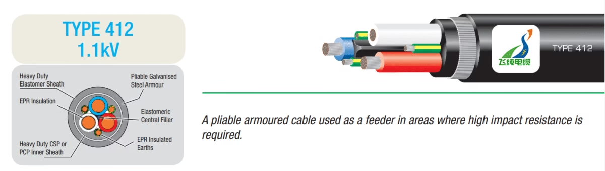
TYPE 412 1.1kV Mining Cables to AS/NZS 2802:2000
Heavy Duty Pliable Armoured Cable for High Impact Mining Applications
Manufactured by Anhui Feichun Special Cable Co., Ltd. (安徽飞纯特种电缆有限公司)
Specialized manufacturer of industrial and mining cables complying with international standards including AS/NZS, VDE, IEC, and other global specifications.
Executive Summary
The TYPE 412 1.1kV mining cable represents a specialized category of heavy-duty armoured power cable engineered specifically for demanding mining operations where maximum mechanical protection and high impact resistance are paramount. Manufactured in strict compliance with the AS/NZS 2802:2000 standard, these cables serve as feeder conductors in applications where equipment damage from external impacts, crushing forces, and severe environmental conditions poses significant operational risks. The AS/NZS 2802:2000 standard specifies requirements for two classes of multicore elastomer insulated and sheathed flexible reeling and trailing cables for surface mining, underground mining (other than coal mining) and general use, with voltage ratings from 1.1/1.1 kV up to and including 33/33 kV.
Unlike standard mining trailing cables that rely solely on flexible sheath protection, TYPE 412 cables incorporate pliable galvanised steel wire armour between the inner and outer sheaths, providing exceptional resistance to mechanical damage while maintaining sufficient flexibility for mining applications. This unique construction makes TYPE 412 cables the preferred choice for sand mining operations, transportable mining substations, fixed pumping installations, conveyor systems, and any semi-permanent distribution network where cables may be exposed to rock falls, vehicle traffic, or equipment impact.
Purpose and Primary Applications
TYPE 412 cables fulfill critical power distribution requirements in mining operations where conventional unarmoured cables prove inadequate due to harsh environmental conditions and severe mechanical stresses. The primary purpose of these cables centers on providing reliable electrical power transmission while withstanding impacts, crushing forces, and abrasion that would rapidly compromise standard cable constructions.
⚙️ Sand Mining Operations
Deployed as primary feeder cables in dredging operations where cables encounter water exposure, sand abrasion, and mechanical impacts from floating equipment and suction machinery.
🔌 Transportable Substations
Used for power supply to mobile mining substations that require periodic relocation as mining faces advance, providing armoured protection during movement and repositioning.
💧 Fixed Pumping Systems
Installed as feeder cables for stationary or semi-permanent dewatering pumps, slurry pumps, and water management systems in open-cut and underground mines.
📦 Conveyor Distribution
Applied in power distribution networks serving conveyor systems, where cables may be exposed to falling material, vehicle crossings, and periodic relocation requirements.
🏗️ Surface Infrastructure
Employed in surface mining infrastructure where cables traverse areas with heavy vehicle traffic or require burial in locations with rocky terrain and potential excavation activity.
🔧 Ancillary Equipment
Connected to crushing plants, screening stations, and processing equipment that operates in fixed or semi-permanent locations requiring enhanced cable protection.
The extreme operating environment of open-cut mining creates unique challenges that standard industrial cables simply cannot address, requiring specialized cable designs with reinforced construction and multiple protection layers. The pliable armour construction distinguishes TYPE 412 from other AS/NZS 2802:2000 cable types, as this category specifically addresses applications where cables remain stationary or experience only intermittent movement, contrasting with continuously flexing reeling cables used on mobile equipment.
Technical Specifications and Construction Materials
Detailed Layer Construction
The TYPE 412 cable employs a sophisticated multi-layer construction where each component serves specific electrical, mechanical, or environmental protection functions. Understanding this construction reveals the engineering sophistication required for reliable mining cable performance.
Material Structure (From Inner to Outer Layers)
- Conductor: Flexible stranded tinned annealed copper conductor conforming to AS/NZS 1125-2.10 specifications. The tinning process provides corrosion resistance in humid mining environments while the multiple fine strands (typically 0.40mm diameter) deliver mechanical flexibility and vibration resistance.
- Insulation: Ethylene Propylene Rubber (EPR) Type R-EP-90 Class 2 according to AS/NZS 3808. EPR insulation offers exceptional electrical properties with dielectric strength exceeding 15 kV/mm, operating temperature range from -25°C to +90°C, and superior resistance to ozone, UV radiation, oils, and chemicals common in mining operations.
- Core Assembly: Three insulated power conductors laid around an elastomeric central filler (cradle) in contact with each other. Three separate EPR-insulated earth conductors (green/yellow identification) positioned in the interstices between power cores.
- Bedding Layer: Elastomeric compound bedding applied over the laid-up cores, providing a smooth foundation for the armour application and protecting cores from mechanical stress during cable flexing.
- Pliable Armour: Galvanised steel wire armour conforming to AS/NZS 3863 specifications, typically constructed from 7 strands of 0.90mm diameter wire applied helically. The pliable construction allows limited cable flexing while providing exceptional impact and crushing resistance with tensile strength exceeding 1400 N/mm².
- Outer Sheath: Heavy-duty elastomeric outer sheath (Type HD-85-PCP or HD-90-CSP) according to AS/NZS 3808, providing final environmental protection against moisture ingress (water absorption less than 1%), chemical attack, UV radiation, abrasion, and flame propagation.
Complete Technical Parameter Table
| Part Number | Voltage (kV) | Conductor Size (mm²) | Conductor Diameter (mm) | Screen Area Each (mm²) | Diameter Over Screen (mm) | Pilot Conductor Size (mm²) | Pilot Diameter (mm) | Inner Sheath Thickness (mm) | Outer Sheath Thickness (mm) | Approx. Cable Diameter (mm) | Approx. Weight (kg/100m) |
|---|---|---|---|---|---|---|---|---|---|---|---|
| MCO-412.1-016 | 1.1 | 16 | 10.4 | 5.3 | 4.2 | — | — | 2.5 | 3.8 | 38.3 | 265 |
| MCO-412.1-025 | 1.1 | 25 | 10.3 | 5.3 | 4.2 | — | — | 2.5 | 3.8 | 38.4 | 294 |
| MCO-412.1-035 | 1.1 | 35 | 11.5 | 5.3 | 4.2 | — | — | 2.5 | 4.0 | 44.1 | 402 |
| MCO-412.1-050 | 1.1 | 50 | 13.3 | 8.06 | 5.3 | — | — | 2.5 | 4.4 | 48.1 | 480 |
| MCO-412.1-070 | 1.1 | 70 | 15.1 | 12.69 | 6.3 | — | — | 2.5 | 4.8 | 54.0 | 627 |
| MCO-412.1-095 | 1.1 | 95 | 17.3 | 15.87 | 6.8 | — | — | 2.5 | 5.4 | 59.4 | 745 |
| MCO-412.1-120 | 1.1 | 120 | 19.1 | 20.1 | 7.9 | — | — | 2.5 | 5.8 | 68.0 | 990 |
| MCO-412.1-150 | 1.1 | 150 | 21.2 | 27.15 | 8.8 | — | — | 2.5 | 6.3 | 74.1 | 1186 |
Electrical Performance Parameters
The electrical characteristics of TYPE 412 cables reflect their optimization for low-voltage power distribution in mining applications. The 1.1kV voltage rating (phase-to-phase and phase-to-earth) accommodates standard mining electrical systems while the conductor sizing range from 16mm² to 150mm² enables current-carrying capacities suitable for diverse equipment power requirements.
Current-Carrying Capacity (Approximate Values)
- 16mm² conductor: 66-75 Amperes (ambient temperature 30°C, laid in air)
- 25mm² conductor: 90-100 Amperes
- 35mm² conductor: 110-125 Amperes
- 50mm² conductor: 140-160 Amperes
- 70mm² conductor: 180-205 Amperes
- 95mm² conductor: 220-250 Amperes
- 120mm² conductor: 260-290 Amperes
- 150mm² conductor: 295-330 Amperes
Note: Actual current-carrying capacity varies with installation method, ambient temperature, grouping factors, and continuous operation versus intermittent loading. Values shown represent approximate continuous ratings for reference purposes.
The conductor DC resistance at 20°C follows standard copper conductor values, with 16mm² conductors exhibiting approximately 1.15 Ω/km and 150mm² conductors approximately 0.124 Ω/km. The EPR insulation provides insulation resistance exceeding 100 MΩ·km at 20°C when new, with minimum acceptable values of 0.5 MΩ·km for in-service cables during routine testing.
Comparison: AS/NZS 2802:2000 TYPE 412 vs VDE 0250-812
Understanding the differences between Australian/New Zealand standard TYPE 412 cables and German VDE 0250 Part 812 cables provides valuable context for international mining operations and helps clarify regional specification requirements. VDE 0250-812 specifies requirements for EPR insulated flexible cables of rated voltages up to and including 450/750V designated as NSSHÖU cables.
AS/NZS 2802:2000 TYPE 412
- Voltage Rating: 1.1/1.1kV (phase-to-earth and phase-to-phase)
- Standard Authority: Standards Australia / Standards New Zealand joint standard
- Primary Market: Australian and New Zealand surface mining, quarries, sand mining operations
- Armour Type: Pliable galvanised steel wire armour (7 × 0.90mm typical) per AS/NZS 3863
- Core Configuration: Three power conductors with three separate interstitial earth conductors (6-core total)
- Sheath Material: Heavy-duty elastomeric compound (HD-85-PCP or HD-90-CSP) per AS/NZS 3808
- Operating Temperature: -25°C to +90°C continuous (conductor temperature)
- Application Focus: Specifically designed for feeder applications where high mechanical impact resistance required, not suitable for continuous reeling
- Testing Requirements: Voltage test 4.2kV AC for 5 minutes, mechanical impact testing per AS/NZS 1660
VDE 0250-812 (NSSHÖU)
- Voltage Rating: 450/750V (conductor-to-earth 450V, conductor-to-conductor 750V)
- Standard Authority: Verband Deutscher Elektrotechniker (Association of German Electrical Engineers)
- Primary Market: European mining, tunneling, mobile equipment, construction machinery
- Armour Type: Generally unarmoured or with optional light wire braid; VDE 0250 series includes separate specifications for armoured variants
- Core Configuration: Typically 3 or 4 core construction with separate earth conductor
- Sheath Material: Polychloroprene (Neoprene) or equivalent synthetic elastomer per DIN VDE 0207
- Operating Temperature: -25°C to +60°C mobile installation, -40°C to +80°C fixed installation
- Application Focus: Designed for mobile machinery, underground mining equipment, tunneling applications with emphasis on flexibility
- Testing Requirements: Voltage test per DIN VDE 0250 general requirements, flame retardancy per DIN VDE 0472
⚠️ Critical Specification Differences
The voltage rating difference represents the most significant distinction between these standards. TYPE 412 cables rated at 1.1kV suit higher voltage Australian mining distribution systems, whereas VDE 0250-812 cables at 450/750V target lower voltage European mobile equipment applications. These cables cannot be directly substituted without comprehensive electrical system review, as voltage ratings, insulation thickness, and safety margins differ substantially.
Additionally, TYPE 412 mandatory galvanised steel wire armour provides impact resistance exceeding typical VDE 0250-812 cable constructions, making TYPE 412 specifically engineered for severe mechanical stress environments where European-standard cables may prove inadequate without additional protection.
VDE 0250 compliant cables find extensive application in underground mining, surface mining, and quarry operations across European markets, offering current capacity up to 587A with temperature ranges from -50°C to +80°C depending on specific cable type and construction. However, direct comparison requires careful consideration of regional electrical standards, equipment voltage requirements, and environmental protection needs specific to each mining operation.
Compliance with International Standards
TYPE 412 cables manufactured by Anhui Feichun Special Cable Co., Ltd. comply with multiple interconnected Australian and New Zealand standards that collectively ensure cable safety, reliability, and performance in demanding mining applications. This comprehensive standards framework addresses every aspect of cable manufacture, testing, and installation.
AS/NZS 2802:2000
Primary governing standard specifying construction requirements, dimensional tolerances, electrical characteristics, and test procedures for reeling and trailing cables in mining applications (excluding underground coal mining).
AS/NZS 1125
Conductor specifications ensuring proper strand construction, tinning requirements, electrical conductivity, and mechanical properties of copper conductors used in mining cables.
AS/NZS 3808:2000
Insulating and sheathing materials standard defining requirements for EPR insulation quality, elastomeric sheath compounds, aging resistance, and environmental protection characteristics.
AS/NZS 3863
Galvanised steel wire specifications for cable armoring, covering wire tensile strength, zinc coating thickness, corrosion resistance, and flexibility requirements.
AS 3007
Electrical installations in surface mines and associated processing plants, providing system-level requirements for cable selection, installation practices, and protection coordination.
AS/NZS 5000.1
General requirements for electric cables, establishing baseline electrical, mechanical, and environmental testing protocols applicable across cable categories.
Beyond Australian and New Zealand national standards, TYPE 412 cables undergo testing according to AS/NZS 1660 (Test methods for electric cables, cords and conductors), which encompasses voltage withstand tests, insulation resistance measurement, conductor resistance verification, flame propagation testing, mechanical impact resistance evaluation, heat aging tests, cold bend testing, and ozone resistance assessment. These comprehensive test protocols ensure cables meet stringent mining industry requirements before deployment in operational environments.
Safety Thresholds and Protection Requirements
Mining operations demand exceptional safety standards due to the combination of high electrical power, harsh environmental conditions, human proximity to equipment, and potential for catastrophic failures. TYPE 412 cables incorporate multiple safety features and must operate within defined thresholds to maintain personnel protection and equipment integrity.
Voltage Withstand and Dielectric Strength
New TYPE 412 cables must withstand routine testing at 4.2 kV AC applied for 5 minutes without breakdown, representing approximately 3.8 times the nominal operating voltage. This substantial safety margin ensures insulation integrity under normal operating conditions including voltage transients, switching surges, and temporary overvoltages encountered in mining electrical systems. The EPR insulation dielectric strength exceeds 15 kV/mm, providing multiple layers of safety against electrical breakdown even if cables experience partial mechanical damage affecting outer protective layers.
Earth Fault Protection
The three separate earth conductors integrated within TYPE 412 cable construction serve critical safety functions beyond simple equipment grounding. These conductors provide low-impedance fault current paths enabling rapid operation of protection devices, maintain equipment frames at earth potential during normal operation preventing dangerous touch voltages, enable earth continuity monitoring systems to detect cable damage before complete insulation failure occurs, and distribute fault currents among multiple paths reducing electromagnetic interference during fault conditions.
✓ Key Safety Parameters
- Maximum Operating Voltage: 1.1kV AC (1.9kV DC equivalent) continuous operation
- Voltage Test Rating: 4.2kV AC for 5 minutes (factory test)
- Minimum Insulation Resistance: 0.5 MΩ·km (in-service), 100 MΩ·km (new cable)
- Maximum Conductor Temperature: 90°C continuous operation, 130°C short-circuit (5 seconds maximum)
- Earth Continuity: Maximum 1.0 Ω end-to-end resistance for earth conductors
- Minimum Bending Radius: 12× cable diameter for permanent installations, 8× during pulling operations
- Impact Resistance: Must withstand 5 Joule impact without sheath penetration per AS/NZS 1660.5.12
- Flame Propagation: Self-extinguishing per AS/NZS 1660.5.3 vertical flame test
Mechanical Protection Ratings
The pliable galvanised steel wire armour provides quantifiable mechanical protection exceeding unarmoured cable constructions. Impact testing per AS/NZS 1660 demonstrates TYPE 412 cables withstand 5 Joule impact energy without armour penetration or damage to inner components, representing approximately 10 times the impact resistance of equivalent unarmoured trailing cables. The armour tensile strength exceeds 1400 N/mm², enabling the cable to support significant tensile loads during installation and withstand crushing forces encountered when cables cross under vehicles or experience rock fall impacts.
Installation Precautions and Best Practices
Proper installation of TYPE 412 cables significantly influences service life, reliability, and safety performance. Mining operations must observe specific precautions during cable handling, installation, termination, and testing to ensure optimal cable performance throughout the operational lifetime.
Pre-Installation Inspection and Storage
Prior to installation, cables require thorough visual inspection for transportation damage including sheath cuts, armour deformation, crushing damage, or moisture ingress through damaged cable ends. Cable reels should be stored outdoors only with waterproof covering, protected from direct sunlight exposure which can degrade outer sheaths despite UV stabilizers, positioned to prevent water accumulation at cable ends where moisture could penetrate between sheath layers, and rotated quarterly during extended storage periods to prevent conductor deformation from prolonged static loading.
Handling and Pulling Operations
Critical Installation Parameters
- Minimum Bending Radius During Installation: 8 times cable overall diameter (e.g., 544mm for 68mm diameter cable)
- Minimum Bending Radius Permanent Installation: 12 times cable overall diameter
- Maximum Pulling Tension: Not to exceed 50 N/mm² conductor cross-sectional area (e.g., 2500N maximum for 50mm² conductor)
- Maximum Sidewall Pressure: 300 N/m cable length in conduit bends
- Temperature During Installation: Minimum -5°C (cable becomes excessively stiff below this temperature)
- Maximum Cable Drum Rotation Speed: 15 RPM to prevent conductor damage from centrifugal forces
Cable pulling operations require dedicated attention to prevent damage that may compromise long-term performance. Pulling eyes or kellums grips must be attached to conductors rather than outer sheath to prevent sheath separation from armour, pulling tensions should be monitored continuously with maximum values never exceeded, lubricants applied generously in conduit installations must be compatible with cable sheath materials (water-based lubricants generally suitable for elastomeric sheaths), and cable routes should be inspected prior to pulling to remove sharp edges or burrs that could damage sheaths during installation.
Termination and Joint Preparation
Proper cable termination ensures electrical integrity and maintains safety margins required for mining operations. Earth conductors must be terminated with adequate mechanical and electrical integrity, typically using compression lugs with terminations resistant to vibration loosening. Armour termination requires proper grounding using armour glands that maintain armour continuity to earth system while providing sheath sealing against moisture ingress. Power conductor terminations must be sized for conductor cross-section with compression crimping tools providing uniform compression throughout barrel length, creating terminations with resistance not exceeding conductor resistance per unit length.
⚠️ Common Installation Errors to Avoid
- Exceeding minimum bending radius causing conductor strand breakage or insulation compression damage
- Omitting or inadequately sealing cable end terminations allowing moisture ingress
- Installing cables in environments where ambient temperature exceeds cable rating
- Failing to provide adequate mechanical support at terminations causing stress concentration
- Cross-connecting earth conductors from multiple cables without proper engineering assessment
- Operating cables at currents exceeding rated capacity leading to excessive temperature rise
- Installing damaged cables discovered during pre-installation inspection
- Using incompatible termination hardware not rated for mining cable construction
Post-Installation Testing and Commissioning
Following installation and before energization, TYPE 412 cables require comprehensive testing to verify installation integrity. Insulation resistance testing should be performed using 1000V DC test voltage applied between each conductor and earth, between conductors, and verification of earth continuity resistance not exceeding 1.0Ω end-to-end. High-voltage proving tests may be specified by mine electrical engineers, typically at 0.8× factory test voltage (approximately 3.4kV) held for 1 minute. All test results should be documented with cable identification, date, ambient temperature, and tested resistance values maintained in permanent mine electrical records.
Common Problems and Troubleshooting Solutions
Mining operations inevitably encounter cable problems during service life. Understanding common failure modes and implementing appropriate corrective actions maximizes cable reliability and minimizes costly production interruptions.
Mechanical Damage and Sheath Failures
External mechanical damage represents the most frequent cable failure mechanism in mining applications. Vehicle traffic over unprotected cables causes sheath compression potentially damaging armour and inner components, rock fall impacts create localized sheath damage with moisture ingress paths to insulation layers, and repeated cable dragging across abrasive surfaces gradually wears through sheath material exposing armour to corrosion.
Corrective Actions for Mechanical Damage
- Minor Sheath Damage (No Armour Exposure): Clean damaged area, apply self-amalgamating tape overwrap extending 100mm beyond damage, followed by PVC tape protective layer. Monitor regularly for damage progression.
- Armour Exposure Without Corrosion: Remove loose sheath material, apply corrosion inhibitor to exposed armour, overwrap with self-amalgamating tape, apply heat-shrink repair sleeve if available, protecting entire damaged section plus 150mm extension each direction.
- Corroded Armour or Damaged Inner Sheath: Cable requires replacement or professional splice installation. Field repairs inadequate for this damage level due to compromised mechanical integrity.
- Conductor Damage Suspected: Perform insulation resistance testing immediately. Values below 1.0 MΩ·km indicate conductor insulation damage requiring cable replacement.
Electrical Insulation Degradation
Insulation degradation occurs gradually through multiple mechanisms including thermal aging from continuous overcurrent operation, moisture ingress through damaged sheaths or poorly sealed terminations, chemical attack from prolonged exposure to oils or solvents incompatible with EPR insulation, and electrical stress from voltage transients exceeding design margins. Insulation resistance testing provides early warning of degradation before complete failure occurs.
Regular insulation resistance testing establishes trending data identifying gradual degradation. New cables exhibit insulation resistance exceeding 100 MΩ·km, declining to 10-50 MΩ·km during first year of service as insulation materials stabilize and minor moisture absorption occurs. Values dropping below 5.0 MΩ·km warrant investigation and increased monitoring frequency, while values below 1.0 MΩ·km indicate approaching failure requiring cable replacement or comprehensive investigation of moisture ingress sources.
Earth Conductor Failures and Continuity Loss
Earth conductor integrity provides fundamental safety protection in mining electrical systems. Common failure mechanisms include mechanical damage to earth conductors from excessive cable bending or pulling tension, corrosion at termination points from moisture exposure and dissimilar metal contact, vibration-induced loosening of termination hardware, and conductor strand breakage from repeated flexing in applications where TYPE 412 cables experience movement beyond design parameters.
Earth continuity testing should be performed annually minimum, with test current not exceeding 10 Amperes DC applied end-to-end. Resistance values exceeding 1.0Ω indicate deteriorating terminations or conductor damage requiring investigation. Complete loss of continuity demands immediate cable de-energization and repair before return to service.
Thermal Overload and Conductor Damage
Operating cables above rated current capacity causes excessive temperature rise leading to accelerated insulation aging and potential thermal runaway failure. Overloading typically results from undersized cable selection for connected equipment, ambient temperature exceeding design conditions reducing effective current capacity, or installation in environments with inadequate heat dissipation such as buried cables in thermally resistant soils.
✓ Preventive Maintenance Best Practices
- Perform visual cable inspections monthly during routine mine site walkthroughs
- Conduct insulation resistance testing annually with results documented and trended
- Verify earth continuity resistance annually ensuring values remain below 1.0Ω
- Monitor connected equipment current draw ensuring operation within cable ratings
- Implement thermal imaging surveys annually identifying hot spots indicating loose connections or overloading
- Maintain cable route protection ensuring adequate barriers against vehicle traffic
- Replace cables approaching end of design life (typically 10-15 years depending on application severity) rather than operating to failure
- Maintain comprehensive cable records including installation dates, test results, repairs performed, and replacement history
Advantages Over Alternative Cable Types
TYPE 412 cables offer distinct advantages compared to alternative mining cable configurations, making them the optimal choice for specific applications requiring maximum mechanical protection combined with electrical performance suitable for 1.1kV systems.
Compared to Unarmoured AS/NZS 2802 Type 409 or Type 441 Cables: TYPE 412 pliable steel wire armour provides dramatically superior impact resistance and crushing protection. While Type 409 and 441 cables rely solely on heavy-duty sheaths for mechanical protection, TYPE 412 armour withstands vehicle crossovers, rock fall impacts, and localized crushing forces that would immediately damage unarmoured cables. This makes TYPE 412 essential for sand mining operations where cables lie exposed on working surfaces, or in processing areas where cables must traverse high-traffic zones. The trade-off involves increased cable weight (approximately 50% heavier than equivalent unarmoured cables) and reduced flexibility making TYPE 412 unsuitable for continuous reeling applications.
Compared to Higher Voltage Type 440 or Type 450 Cables: For applications operating at 1.1kV system voltage, TYPE 412 offers optimal cost-effectiveness without the unnecessary complexity of medium-voltage cable construction. Type 440 and 450 cables rated for 3.3kV through 33kV incorporate semiconductive conductor screening, insulation screening layers, and composite earth screen assemblies that substantially increase cable cost, diameter, and weight. Mining operations with 1.1kV distribution systems gain no benefit from these features, making TYPE 412 the economically rational choice delivering required electrical performance and mechanical protection without premium pricing for unused capabilities.
Compared to VDE 0250 Series European Cables: TYPE 412 higher voltage rating (1.1kV vs 450/750V) enables application in Australian mining distribution systems without voltage derating concerns. The mandatory galvanised steel armour provides standardized mechanical protection without relying on optional cable constructions or additional protective conduits. AS/NZS 2802:2000 compliance ensures cable suitability for Australian regulatory requirements and mining codes, simplifying approval processes and reducing compliance risk.
Authoritative References and Industry Resources
- AS/NZS 2802:2000 – Electric cables – Reeling and trailing – For mining and general use (Standards Australia)
- AS/NZS 2802 Mining Cable Applications in Australian Open-Cut Operations (Amplex Mining)
- Heavy Duty Reeling Cable Specifications and Applications (Reeling Cable)
- DIN VDE 0250-812 Standard Specifications (VDE Publishing House)
- AS/NZS 2802 Standard Overview and Cable Types (Tratos Group)
Contact Anhui Feichun Special Cable Co., Ltd.
For technical specifications, quotations, or engineering support regarding TYPE 412 mining cables
[email protected]
[email protected]
+86 138 5512 3218
Conclusion
TYPE 412 1.1kV mining cables manufactured to AS/NZS 2802:2000 specifications represent specialized engineering solutions addressing the unique demands of mining operations requiring maximum mechanical protection combined with reliable electrical performance. The pliable galvanised steel wire armour construction distinguishes these cables from alternative mining cable types, providing exceptional impact resistance and crushing protection while maintaining sufficient flexibility for practical installation and limited operational movement.
Understanding the complete technical specifications, proper installation procedures, maintenance requirements, and operational limitations ensures mining operations derive maximum value from TYPE 412 cable investments. The substantial mechanical protection afforded by armoured construction justifies the premium cost compared to unarmoured alternatives in applications where cable damage from external impacts represents significant operational risk. Conversely, recognizing TYPE 412 limitations regarding continuous flexing applications prevents misapplication that could lead to premature cable failure.
Comparison with international standards including VDE 0250-812 clarifies regional specification differences and assists multinational mining operations in making informed cable selection decisions based on voltage requirements, mechanical protection needs, and regulatory compliance obligations. The comprehensive standards framework governing TYPE 412 cables including AS/NZS 2802:2000, AS/NZS 1125, AS/NZS 3808, and AS/NZS 3863 ensures manufactured cables meet stringent quality requirements appropriate for demanding mining environments where equipment reliability directly impacts both safety and operational continuity.
Anhui Feichun Special Cable Co., Ltd. maintains manufacturing capabilities delivering TYPE 412 cables meeting these exacting standards while providing technical support assisting mining operations with proper cable selection, installation guidance, and troubleshooting support throughout cable operational lifetimes. Whether supplying sand mining operations, transportable substations, fixed pumping installations, or semi-permanent distribution networks, TYPE 412 cables deliver the mechanical robustness and electrical performance required for reliable mining power distribution systems.


