
盾构机刀盘供电系统:如何正确选择 (N)TSCGEWÖU 3×120+3×70/3 12/20kV 柔性供电电缆
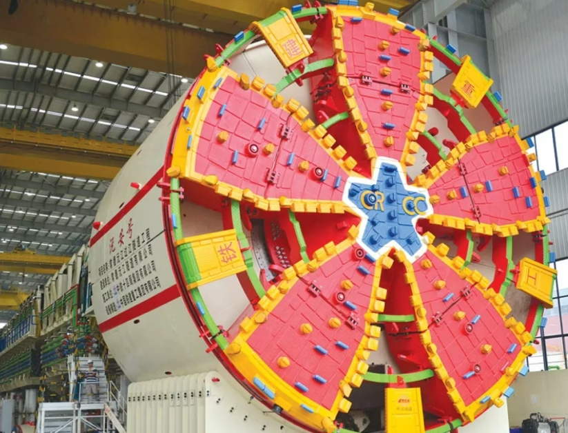
TBM Cutterhead Power Supply: How to correctly size (N)TSCGEWÖU 3×120+3×70/3 12/20kV flexible reeling cable for tunnel boring machine main drive systems 盾构机刀盘供电系统:如何正确选择 (N)TSCGEWÖU 3×120+3×70/3 12/20kV 柔性供电电缆
A comprehensive technical guide for electrical engineers designing and specifying power distribution systems for tunnel boring machines (TBM) engaged in hard-rock tunneling and soft-ground excavation. This document provides practical ampacity ratings for the (N)TSCGEWÖU 3×120+3×70/3 12/20kV medium-voltage trailing cable under actual TBM duty cycles, including continuous-duty ampacity for main cutterhead drive motors typically rated 1.5–3.0 megawatts, mechanical stress derating factors accounting for high-frequency dragging and reeling cycles in backup gantry systems, temperature considerations in confined underground tunnel environments where cooling is naturally limited, cumulative derating effects when multiple power cables are bundled alongside control and monitoring lines, practical field installation and termination procedures for harsh underground conditions, and comprehensive safety verification protocols to prevent power loss to the main cutterhead during critical excavation operations. — 为 TBM 盾构机中压供电系统的连续载流量、机械拉力降额、温度修正和现场施工验证提供综合技术指南,特别针对硬岩掘进和软地层开挖应用。
1. Direct Answer for Engineering Specs: TBM Cutterhead Ampacity Ratings 工程规格直接答案:盾构机刀盘载流量额定值
The continuous ampacity of (N)TSCGEWÖU 3×120+3×70/3 12/20kV flexible reeling cable is 360 amperes when operating as a single conductor run in free air at the reference condition of 30°C ambient temperature and 90°C conductor operating temperature according to VDE 0250-813 and DIN VDE 0298-4 standards. For tunnel boring machine cutterhead power supply applications where the cable is installed in the constrained environment of a TBM backup gantry system—bundled alongside control cables, communication lines, and other power feeders—and subjected to frequent mechanical stress from dragging and reeling operations, the practical safe ampacity derates to approximately 260–285 amperes depending on specific installation geometry, tunnel temperature profile, and frequency of mechanical cycling. These two ampacity values represent the boundary between theoretical maximum current capacity and the practical operating limit for reliable power delivery to a 2–3 megawatt main cutterhead drive motor in a hard-rock tunneling or soft-ground excavation system. Understanding where these values come from and how they apply to specific TBM configurations is essential for preventing unexpected power loss to the cutterhead, which could force a full machine shutdown and result in schedule delays of weeks or months in confined underground construction.
The significance of the 360-ampere versus 260–285-ampere distinction extends beyond simple technical ratings. In practical TBM operations, the main cutterhead operates at approximately 80–90% of its designed motor ampacity under normal excavation conditions, with brief excursions to higher current during breakout (initial boring into virgin rock) or when encountering localized hard strata. A cable system designed with inadequate safety margins may operate adequately during routine conditions but will overheat and fail exactly when the main cutterhead demands highest power—precisely when you cannot afford interruption. Conversely, a cable system oversized relative to actual load would consume valuable space in the backup gantry, add unnecessary weight to the total machine, and increase equipment cost without providing proportional benefit. The art of TBM electrical engineering lies in selecting precisely the right cable size such that actual load current under normal excavation consumes approximately 75–85% of the derated ampacity limit, maintaining sufficient safety margin for temporary overload conditions without requiring oversized cable.
Critical Safety Warning ⚠️ 关键安全警告: A tunnel boring machine main cutterhead represents the single point of failure for the entire excavation system. If power is lost to the main drive motor while the cutting head is engaged in rock, the entire machine becomes a fixed object embedded in the tunnel face, unable to pull back or advance. Clearing the obstruction requires hours or days of emergency work, often in extremely difficult conditions, potentially costing hundreds of thousands of dollars per day in lost production and mobilization of heavy rescue equipment. A cable failure on the main cutterhead power line is not merely an inconvenience—it is a catastrophic operational event. Therefore, the absolute requirement for TBM cutterhead power cables is zero tolerance for overload conditions. The cable must NEVER operate above its thermally-derated ampacity limit, regardless of project schedule pressures. Always verify that the actual load current measured during commissioning is below 85% of the design ampacity limit, and implement protective controls to prevent sustained overload. Design the electrical system with adequate ampacity margin to accommodate occasional temporary overloads during breakout, but never allow continuous operation at elevated current.
2. Understanding TBM Power Supply Requirements: Why This Cable Size Matters 理解盾构机供电需求:为什么这个规格很重要
To correctly size the (N)TSCGEWÖU cable for a tunnel boring machine main cutterhead drive, we must first understand the electrical load profile and operational environment that this cable must serve. Unlike typical industrial power cables in fixed installations, TBM cutterhead power cables operate under a unique combination of electrical, mechanical, and environmental stresses that demand special consideration.
The main cutterhead motor on a modern tunnel boring machine is typically a three-phase synchronous or induction motor rated between 1.5 and 3.0 megawatts at 12 kV or 20 kV voltage. During normal excavation operations, this motor rotates the cutterhead at 4–12 revolutions per minute while delivering constant torque to cut and fracture rock or soil. The electrical current drawn by the motor during normal steady-state boring is approximately 90–110 amperes per phase for a 2.0 MW motor at 12 kV, or slightly lower for the same motor at 20 kV voltage. However, TBM operations are not smooth or constant. When the cutterhead first engages virgin rock (called breakout), the motor experiences a sudden mechanical load spike as the cutting tools bite into fresh material. Current can temporarily surge to 150–200 amperes per phase for 30 seconds to 2 minutes until the cutterhead develops a penetration groove and the load stabilizes. When encountering boulders, fault zones, or unexpectedly hard strata, current can spike even higher. At the other extreme, when the cutterhead is pulling back (retracting) for muck removal or escaping from a jam, current may drop to 20–40 amperes. The cable must safely handle the steady-state normal operating current indefinitely, plus brief excursions to elevated current during transient conditions.
Beyond electrical load, the (N)TSCGEWÖU cable on a TBM endures mechanical stresses unknown in fixed installations. The cable is continuously reeled and unreeled as the machine advances. With each meter of advance, the cable pays out from the storage reel in the backup gantry. The cable experiences dynamic bending stress as it passes through cable guides, support clamps, and around the pulleys and sheaves that control the reeling process. The cable can be pulled by hand during manual positioning, or dragged across rough tunnel floor and over rocky obstructions. In difficult terrain, the cable may be run over sharp edges or across rough concrete. All of these mechanical stresses accelerate fatigue and can reduce the effective ampacity if the installation is not carefully managed. The cable must therefore be engineered not merely for continuous current capacity, but for the combination of current capacity plus mechanical durability under high-frequency bending and dragging cycles.
2.1 Why Underground Tunnel Environment Changes the Ampacity Picture 为什么地下隧道环境改变了载流量的情景
The confined tunnel environment of underground construction introduces thermal challenges unique to TBM installations. Unlike surface industrial installations where cables can dissipate heat freely to ambient air or to water-cooled systems, cables in a tunnel bore operate in a confined space with limited air circulation. The ambient temperature deep in the tunnel is typically 10–20°C cooler than surface conditions, which provides some thermal benefit. However, when the TBM operates continuously during a round-the-clock excavation shift—which is common in rapid-advance projects—the cumulative heat generation in the confined space can raise the local ambient temperature around the cable bundle several degrees above the far-field tunnel temperature. The combination of confined space, limited ventilation, and continuous duty operation means that temperature derating for TBM cables is typically more severe than for cables in open-air industrial installations. A cable that could carry 360 amperes indefinitely in free air at 30°C ambient may only safely carry 280–300 amperes in the actual confined tunnel environment where local ambient temperatures are elevated due to continuous machine operation.
3. The (N)TSCGEWÖU Cable: Design for Mechanical Stress and Continuous Duty (N)TSCGEWÖU 电缆:机械应力和连续工作的设计
The (N)TSCGEWÖU designation follows European cable naming conventions and encodes important information about the cable’s design purpose and material composition. Breaking down the designation: the letter N indicates “neopathic” (robust for harsh mechanical environments), the letters TSCGEWÖU identify a specific cable type in the German VDE and international IEC standards families, and the 3×120+3×70/3 describes the conductor configuration—three primary phases of 120 square millimeters each plus a symmetrically distributed three-part grounding conductor of 70 square millimeters total (divided as 3×23.3 mm² per segment). The voltage rating of 12/20 kV means the cable is designed for a 12 kV phase-to-neutral working voltage with a maximum system voltage of 20 kV phase-to-phase, suitable for underground distribution systems and direct connection to transformer secondaries feeding medium-voltage motors.
The engineering advantages of this specific cable design become apparent when examining its construction. The three-core stranded copper conductor uses Class 5 flexibility classification, meaning the conductor is composed of many fine strands (approximately 100–150 individual wires per conductor) rather than a few large wires. This multi-strand construction provides exceptional resistance to fatigue cracking under bending cycles. A conductor with only a few large strands—sometimes called Class 1 or Class 2—would fail after thousands of bend cycles due to stress concentration in the large individual wires. The Class 5 design distributes bending stress across many small wires, allowing the conductor to survive hundreds of thousands of bend and flex cycles without fatigue failure. For TBM applications where the cable may be reeled and unreeled a thousand times during the course of a tunnel drive, this fatigue resistance is essential.
The insulation system consists of EPR (ethylene propylene rubber) rated for 90°C continuous operation, providing thermal stability and good resistance to moisture and chemical attack in the damp underground environment. The outer sheath is special high-grip red rubber (designated 5GM5 or equivalent), engineered for resistance to abrasion, tearing, ozone exposure, and UV degradation. The “red rubber” designation indicates this is not the cheaper black rubber often used for general industrial cables, but a premium compound optimized for mechanical durability. The cable’s core-to-sheath configuration includes a special anti-torsion braid—a helical wire or textile layer that resists twisting when the cable is dragged or when rotation is applied during reeling. This feature is specifically designed to prevent the cable from developing a kink or spiral deformation when subjected to mechanical stress, which would otherwise concentrate mechanical strain and lead to premature failure.
3.1 Symmetrical Earth Core Design for TBM Electrical Safety 对称接地导体设计用于盾构机电气安全
One distinctive feature of the (N)TSCGEWÖU is the symmetrical three-part earth/ground core (3×70/3 means three segments of approximately 23.3 mm² each). Rather than concentrating the entire ground conductor as a single large conductor running alongside the three power phases, the ground is split into three smaller conductors positioned in the spaces between the main power phases. This symmetrical arrangement provides important electrical benefits. When large three-phase currents flow through the power conductors, they create rotating magnetic fields that induce voltages in any nearby conductors. A ground conductor placed far from the power phases experiences unequal magnetic induction and develops high induced voltage, which can create unexpected potential differences and safety hazards in the TBM metal structure. By distributing the ground conductor symmetrically around the three phases, the magnetic induction is equalized and the induced voltage in the ground conductor is nearly zero regardless of load current. This keeps the TBM’s metal frame and cutterhead at consistent potential, reducing the risk of touch voltage hazards and improving personnel safety during maintenance and emergency operations.
4. Continuous Ampacity at Reference Conditions: The 360-Ampere Baseline 参考条件下的连续载流量:360 安培基准
The 360-ampere rating for the (N)TSCGEWÖU 3×120+3×70/3 cable emerges from detailed thermal analysis conducted according to VDE 0250-813 (the German heavy-duty industrial and mining cable standard) and DIN VDE 0298-4 (the German standard for current-carrying capacity calculations). The reference condition specifies 30°C ambient temperature, which represents typical conditions in sheltered industrial installations or average underground temperatures at moderate depths. The cable is tested or calculated to confirm that when carrying 360 amperes continuous, the conductor reaches exactly 90°C (the maximum permissible temperature for EPR insulation) under this reference condition.
The thermal analysis follows the same fundamental principle as other cable systems: power dissipated as heat (P = I²R) must equal the heat dissipating to the environment through the cable insulation and sheath. For the 2 AWG (120 mm²) copper conductor in the (N)TSCGEWÖU, the DC resistance at 20°C is approximately 0.1524 ohms per kilometer. However, when the cable operates at 90°C conductor temperature, the actual resistance increases due to the positive temperature coefficient of copper. At 90°C, the resistance increases to approximately 0.1895 ohms per kilometer. When 360 amperes flows through this resistance, the power dissipated per kilometer is P = (360)² × 0.1895 = 129,600 × 0.1895 ≈ 24,550 watts per kilometer.
This 24,550 watts per kilometer of heat must dissipate through the cable’s EPR insulation and rubber sheath to the surrounding environment (air in the backup gantry). The thermal resistance of the insulation and sheath system, combined with the cable’s geometry and the heat transfer characteristics to ambient air, determines how much temperature rise results from this heat flow. For the (N)TSCGEWÖU with its specific insulation thickness and sheath materials, the thermal calculations show that the temperature rise from the ambient to the conductor surface is approximately 60°C when 360 amperes flows. Thus, at 30°C ambient plus 60°C rise due to I²R losses, the conductor reaches 90°C. This is precisely the target: at the rated ampacity of 360 amperes, the conductor reaches the maximum permissible temperature of 90°C and no higher.
The reference condition of 30°C rather than 20°C (which might seem more “standard”) reflects practical experience with TBM installations. Tunnels in temperate zones typically have ambient temperatures of 10–30°C depending on depth and geological conditions. The 30°C reference represents a reasonably warm but realistic tunnel condition. When cables operate in cooler environments (such as deep tunnels in polar regions), the ampacity can be increased slightly through temperature derating. When cables operate in warmer environments (such as shallow tunnels in tropical regions or heat from continuous TBM operations), the ampacity must be reduced.
5. Mechanical Stress Derating: Accounting for Dragging, Reeling, and Repetitive Flexure 机械应力降额:考虑拖拽、卷绕和重复弯曲
The most distinctive derating factor for TBM cables is the reduction in ampacity caused by mechanical stress. Unlike fixed industrial cables that stay in one location for years, TBM cables experience high-frequency bending, dragging, and tension stresses that accelerate internal fatigue and can reduce the effective ampacity if not properly accounted for.
When a cable is bent or flexed, the outer layers of the insulation experience tensile strain while the inner layers experience compressive strain. If the cable is bent too sharply, the strain exceeds the mechanical limits of the insulation material, causing micro-cracking at the molecular level. Even bends that stay within the mechanical limits of the material cause cumulative fatigue: thousands of bend cycles accumulate damage that eventually leads to insulation failure or partial discharge. The VDE 0250-813 standard for (N)TSCGEWÖU cables specifies a minimum dynamic bending radius of 15 times the cable outer diameter (approximately 15 × 66 mm = 990 mm, or roughly one meter). This specification represents the radius at which the cable can be bent repeatedly without accelerated degradation. When the cable is bent to a radius smaller than 15×OD, fatigue damage accumulates rapidly.
In practical TBM backup gantry installations, the cable is bent continuously as it reels and unreels. The cable passes around guide rollers, support clamps, and storage reel pulleys. Each meter of cable advance results in one complete cycle of reel rotation, with the cable experiencing multiple bend cycles per meter. In a tunnel drive that advances 300 meters per day (a typical round-the-clock advance rate), the cable experiences approximately 1,500 bend cycles per day. Over a 500-meter tunnel drive lasting a month, the cable may experience 45,000 bend cycles. Over a 5-kilometer tunnel drive lasting 6 months, the cable experiences 450,000 bend cycles. This high-frequency mechanical cycling introduces fatigue stress that reduces the effective ampacity.
The mechanical stress derating factor is applied by reducing the ampacity in proportion to the severity of mechanical stress. For TBM cables operated under controlled conditions in a well-maintained backup gantry with proper guide rollers, cable clamps, and reel design, the mechanical stress derating is typically 10–15%, reducing the ampacity from 360 A to approximately 305–320 A. However, for TBM installations in difficult terrain where cables may be dragged over rough ground, across sharp edges, or over obstacles, the mechanical stress derating can be as severe as 20–25%, reducing the ampacity to 270–290 A. Cables that are improperly handled during installation—kinked, twisted, or severely bent—may suffer permanent damage that reduces ampacity even further.
5.1 Practical Mechanical Stress in Challenging Tunnel Conditions 具有挑战性的隧道条件中的实际机械应力
Consider a real-world TBM project in mixed-face geology where the machine encounters both soft soil and hard rock. During the soft-soil sections, the machine advances rapidly (5–6 meters per shift), and the cable is handled gently with minimal dragging or mechanical stress. In these sections, the mechanical derating can be held to approximately 12%, allowing near-maximum ampacity. However, when the machine encounters a hard-rock section and must slow to 2–3 meters per shift with high cutterhead load, the cable may need to be manually repositioned, pulled over rough tunnel rubble, and flexed more severely to maintain advance. In these difficult sections, the mechanical derating increases to approximately 20%, reducing the effective ampacity by a larger margin. A properly designed TBM power system accounts for these varying conditions and provides sufficient ampacity margin to cover the worst-case mechanical stress scenarios anticipated for the specific tunnel geology.
6. Temperature Derating: Operating in Confined Tunnel Environments 温度降额:在密闭隧道环境中运行
The 30°C reference ambient temperature on which the 360-ampere rating is based assumes a stable, moderate underground environment. However, TBM tunnels can experience temperature variations depending on tunnel depth, geology, ventilation conditions, and the thermal load from the operating machine itself. Understanding how to derate ampacity for actual tunnel conditions is essential for correct cable sizing.
The fundamental relationship between ambient temperature and ampacity follows from the fact that the maximum allowable conductor temperature is fixed at 90°C. If the ambient temperature increases, the temperature rise available from I²R losses must decrease proportionally to prevent the conductor from exceeding 90°C. The mathematical relationship shows that ampacity is proportional to the square root of the temperature rise available. If the ambient temperature increases by 5°C (from 30°C to 35°C), the available temperature rise decreases from 60°C to 55°C, and the ampacity must reduce by a factor of √(55/60) ≈ 0.957, or approximately 4.3%. If the ambient increases by 10°C (to 40°C), the derating factor becomes √(50/60) ≈ 0.913, or approximately 8.7% reduction in ampacity.
In practical TBM operations in temperate climate zones, the far-field tunnel temperature at the boring face is typically 5–15°C cooler than surface temperature. However, around the active TBM machine, the local ambient temperature can rise significantly due to the cumulative heat from the cutterhead motor, hydraulic systems, and the friction of the boring process itself. Additionally, during continuous 24/7 operations over multiple days, the tunnel segment behind the machine (where the backup gantry and power cables are located) gradually warms due to residual heat from the machine. Temperature measurements in operating TBM tunnels show that while the far-field ambient is 15°C, the local temperature around the cable in the backup gantry area can reach 25–30°C. For conservative design, the cable ampacity should be derated for a 25–30°C local ambient temperature rather than the ideal 15°C far-field temperature, accounting for this thermal accumulation effect.
In tropical regions where tunnels are shallow, or in geothermal areas where ground temperature is naturally elevated, the derating becomes more severe. A tunnel in Southeast Asia at 200-meter depth might have a far-field ambient temperature of 30–35°C. Combined with thermal accumulation from TBM operations, the local cable ambient could reach 35–40°C. A 35°C local ambient requires a derating factor of √(55/60) ≈ 0.957, or approximately 4–5% reduction. A 40°C local ambient requires √(50/60) ≈ 0.913, or approximately 9% reduction. These temperature deratings are cumulative with the mechanical stress deratings discussed in the previous section, resulting in overall ampacity reductions of 15–20% or more.
7. Bundling and Cable Tray Derating: Multiple Cables in Backup Gantry Systems 束线和电缆桥架降额:后配系统中的多根电缆
The 360-ampere reference ampacity assumes the cable operates as an isolated single conductor with free air circulation all around it. In reality, TBM backup gantry systems contain multiple cables: the three main cutterhead power cables (all part of the same (N)TSCGEWÖU installation), plus separate control cables for the cutterhead hydraulics, instrumentation cables for tunnel survey and machine diagnostics, communication cables for personnel and voice communication, and often additional auxiliary power feeders for lighting and surface coordination. All of these cables are installed in close proximity, often bundled together or installed in cable trays mounted on the backup gantry structure.
When multiple cables are installed close together, the heat dissipation from each cable is reduced because the thermal barrier created by adjacent cables reduces the efficiency of convective cooling to the surrounding air. The heat generated by one cable heats the air around it, and this warmed air then contacts adjacent cables, reducing their ability to dissipate heat. The effect is similar to the cable tray derating discussed in fixed industrial installations, but typically more severe in TBM installations because the cables are often bundled more tightly in the confined space of the backup gantry frame.
For a typical TBM backup gantry system where 8–12 cables are bundled together, the bundling derating factor is approximately 0.85–0.90, representing a 10–15% reduction in ampacity compared to isolated cable operation. In very tightly bundled configurations, the derating can be as severe as 0.80, representing a 20% reduction. The specific derating depends on the cable arrangement: cables arranged in a single layer with good spacing between them experience less derating than cables arranged in multiple layers or tightly packed together.
The VDE standard provides detailed bundling derating tables for various configurations. A competent cable installation engineer should consult these tables specific to the actual cable arrangement in the TBM backup gantry and apply the appropriate derating factor. When multiple derating factors must be combined (mechanical stress plus bundling, for example), the factors multiply rather than add. A cable with a 15% mechanical stress derating (factor 0.85) and a 15% bundling derating (factor 0.85) experiences a cumulative derating of 0.85 × 0.85 = 0.7225, or approximately 27.75% reduction from the reference 360 amperes, down to approximately 260 amperes.
8. Cumulative Derating: Real-World TBM Power System Scenarios 累积降额:现实世界的盾构机供电系统情景
In practice, TBM cable installations rarely involve a single derating factor in isolation. Instead, multiple derating factors combine to determine the actual safe ampacity for a specific TBM configuration and operating environment. Understanding how to systematically apply multiple derating factors is essential for correct cable sizing.
Consider a realistic example: a hard-rock TBM deployed in a moderately deep tunnel in a temperate climate, advancing through mixed geology. The cable selection and derating analysis proceeds as follows:
Step 1 — Reference Ampacity: Start with the VDE reference value of 360 amperes for a single (N)TSCGEWÖU 3×120+3×70/3 cable in free air at 30°C ambient.
Step 2 — Mechanical Stress Derating: The tunnel geology is mixed, with sections of soft ground and hard rock. The machine will be subject to occasional difficult conditions requiring manual cable repositioning and dragging. Apply a conservative mechanical stress derating factor of 0.87 (13% reduction), accounting for these challenging conditions. New ampacity: 360 × 0.87 = 313 A.
Step 3 — Temperature Derating: The tunnel is at 300-meter depth in a temperate zone with far-field ambient temperature of 18°C. However, during continuous 24/7 TBM operations, the local cable ambient in the backup gantry rises to approximately 28°C due to thermal accumulation. Apply temperature derating for 28°C ambient. The derating factor is √((90-28)/(90-30)) = √(62/60) ≈ 1.017, which is actually a slight ampacity increase from the 30°C reference. However, to remain conservative, assume the local ambient could reach 30°C, resulting in no additional temperature derating. New ampacity remains: 313 A.
Step 4 — Bundling Derating: The backup gantry has approximately 10 cables bundled together in a moderately packed configuration. The bundling derating factor is approximately 0.88 (12% reduction). New ampacity: 313 × 0.88 = 275 A.
Step 5 — Design Safety Factor: The calculated ampacity of 275 A represents the absolute maximum safe continuous current. However, prudent design practice dictates operating the cable at approximately 85–90% of the calculated limit to maintain safety margin for occasional transient overloads during breakout or obstacle encounter. Therefore, the design continuous ampacity for actual motor branch current specification is 275 × 0.87 ≈ 240 A.
This realistic scenario shows how the reference 360-ampere rating reduces to a practical design value of approximately 240 amperes through the cumulative application of mechanical, temperature, and bundling derating factors. A motor that draws more than 240 amperes during sustained operation would exceed the design ampacity limit and represents an unacceptable risk for power loss to the cutterhead. If the actual motor load exceeds this limit, a larger cable size must be selected, or the system design must be modified to reduce load (for example, by improving rock penetration efficiency to reduce required cutterhead torque).
| Scenario 场景 | Tunnel Ambient 隧道环境温度 | Mech. Stress 机械应力 | Bundling 束线 | Calc. Ampacity 计算载流量 | Design Limit 设计限值 |
|---|---|---|---|---|---|
| Hard-rock temperate zone 温带硬岩 | 28°C | 0.87 | 0.88 | ~275 A | 235–250 A |
| Soft-ground rapid advance 软地层快速推进 | 25°C | 0.92 | 0.88 | ~298 A | 255–270 A |
| Tropical deep tunnel 热带深隧道 | 32°C | 0.85 | 0.85 | ~261 A | 220–235 A |
| Arctic shallow tunnel 北极浅隧道 | 5°C | 0.90 | 0.88 | ~322 A | 275–290 A |
9. Field Installation: Proper Handling, Reeling, and Cable Management 现场安装:适当处理、卷绕和电缆管理
Correct field installation of the (N)TSCGEWÖU cable is absolutely essential for achieving the calculated ampacity in actual operation. Improper handling during installation can cause permanent damage that reduces ampacity significantly or causes complete failure within weeks of operation. The following procedures should be followed by all personnel involved in TBM cable installation and management.
9.1 Receiving and Inspection Procedures 接收和检查程序
When the cable arrives at the project site, inspect the entire shipment immediately for damage during transportation. The cable should arrive on a heavy-gauge metal flange reel with adequate reinforcement to support the weight (typically 7,800–8,300 kg per kilometer for the (N)TSCGEWÖU). The reel flanges should show no deformation or permanent bending. Inspect the cable surface for cuts, gouges, kinks, or other mechanical damage. If the cable has been exposed to sharp edges or heavy impacts during transport, reject the shipment and contact the supplier. Any cable with visible damage to the insulation or outer sheath should not be installed; repair is not practical, and installation of damaged cable will inevitably lead to failure in the underground environment.
Measure the cable diameter at several locations along the first 50 meters of cable. The nominal outer diameter for (N)TSCGEWÖU 3×120+3×70/3 is 64–69.5 mm. If measured diameter is significantly outside this range (less than 62 mm or greater than 72 mm), the cable may have been compressed or exposed to temperature extremes during storage, and its electrical properties may be compromised. Contact the supplier for verification.
9.2 Storage and Handling Before Installation 安装前的存储和处理
Store cable on the reel in a dry, sheltered location. The cable should be protected from direct sunlight (UV degradation of the outer sheath), temperature extremes (which can degrade the rubber compounds), moisture (which can cause water ingress), and physical damage (dropped equipment, vehicle traffic, etc.). If the cable must be stored outdoors, provide a protective covering such as a tarpaulin to shield from weather.
Handle the reel with heavy equipment appropriate to its weight—never attempt to manually roll or position a 35-ton cable reel by hand. Use mobile equipment such as a crane or heavy-duty forklift with proper spreader bars to distribute load. When moving the reel, ensure the spindle is properly supported at both ends to prevent reel flanges from bending under the cable weight. Avoid sudden impacts, rapid acceleration, or aggressive maneuvering that could cause the cable to shift and bind against the reel flange.
9.3 Proper Reeling and Unreeling During Advance 推进过程中的适当卷绕和放线
The cable is pulled from the reel as the TBM advances. The reeling system should be equipped with guide rollers and support structures that maintain the minimum dynamic bending radius of 15 times the cable outer diameter (approximately 1 meter radius). All guide rollers should be smooth, free-rolling, and properly aligned to prevent the cable from rubbing against the roller edges or flanges. Regularly inspect the guide rollers for wear, dirt accumulation, or debris that could damage the cable.
The cable should pay out from the top of the reel in a controlled manner, not from the side where it would twist or develop spiral deformation. Use a cable carrier or cable tray that supports the cable continuously as it leaves the reel, preventing it from dragging on the ground or becoming tangled. When the TBM advances into difficult terrain requiring manual repositioning, do not drag the cable violently or bend it sharply around obstacles. Instead, carefully position the cable to avoid sharp bends, and use cable rollers or temporary supports to protect the cable from contact with rough ground or sharp edges.
9.4 Avoiding Common Installation Errors 避免常见的安装错误
The most destructive error in TBM cable installation is sharp kinking—an abrupt bend to a radius much smaller than the specified minimum dynamic bending radius. A sharp kink concentrates strain in a small region of the conductor and insulation, causing immediate micro-cracking and permanent damage. The cable may continue to function temporarily, but the internal damage will lead to failure within days or weeks of operation. Sharp kinks typically occur when cables are manually pulled around corners, bent to fit through tight spaces, or caught under equipment. To prevent kinking, always maintain a smooth, gradual bend with radius at least 15 times the cable diameter, and never force the cable into confined spaces. If the cable cannot fit through a space with adequate bend radius, the route must be modified or additional cable guides must be installed.
A second destructive error is twisting of the cable during reeling. The anti-torsion braid on the (N)TSCGEWÖU is designed to resist twisting, but excessive torsional stress can override this protection. Twisting typically occurs when the cable is pulled from the reel at an angle, or when the reel itself rotates during unreeling. To prevent twisting, ensure the reel is fixed and does not rotate as cable is pulled. If the cable begins to develop a spiral shape or “cork-screw” appearance, stop immediately and allow the cable to relax before continuing.
10. Cutterhead Termination: High-Voltage Connection Safety in Underground Conditions 刀盘终端:地下条件下的高压连接安全
The termination of the (N)TSCGEWÖU cable at the TBM cutterhead motor is one of the most critical operations in TBM electrical commissioning. A failed or faulty termination will cause power loss to the cutterhead drive at the worst possible time—often when the machine is engaged in difficult excavation and cannot afford interruption.
The termination procedure for 12/20 kV cables requires removal of the outer sheath and several layers of internal protective material to expose the conductor and insulation. The cable’s cross-section consists, from inside to outside: the copper conductor (which is carrying the high current), an inner semi-conductive layer (which shields the conductor from field effects), the main EPR insulation, an outer semi-conductive layer (which provides shielding and surface protection), a copper tape shield (which provides electromagnetic shielding), and finally the outer rubber sheath.
The most common error in termination is accidentally cutting or gouging the outer semi-conductive layer or the main EPR insulation during stripping. Even a minor scratch—perhaps 1–2 mm wide and just barely breaking the surface—creates a microscopic defect that will become the site of partial discharge (PD) under the high electrical field stress of 12/20 kV operation. Partial discharge is a small electrical spark occurring within the insulation, causing gradual degradation and ionization of the insulation material. The PD becomes self-sustaining and accelerates over hours to days, eventually leading to complete insulation breakdown and arcing.
To prevent this critical error, use only specialized high-voltage cable stripping tools specifically designed for medium-voltage cable termination. Manual stripping with knives or utility blades is not acceptable—the risk of insulation damage is too high. After stripping with proper tools, carefully inspect the insulation surface under bright light for any scratches, nicks, or damage. If any damage is visible, that section of cable cannot be salvaged. The cable must be cut back past the damaged section, and stripping must begin again at a new location. There is no safe way to repair or patch scratched high-voltage insulation.
The termination connector (a specialized high-voltage cable lug or bushing designed for 12/20 kV) must be properly crimped to the conductor according to the manufacturer’s specification. Improper crimping—too loose or too tight—will create high contact resistance and localized heating at the termination. Use a calibrated crimping tool with the exact die specified for the conductor size and termination type. After crimping, measure the crimp dimensions to verify they fall within specification.
The entire termination assembly must be sealed against moisture ingress using specialized high-voltage termination compound or heat-shrink tubing designed for 12/20 kV service. The sealing must prevent water from contacting the insulation surface or the conductor strands, as moisture will reduce insulation resistance and promote partial discharge. In the damp underground TBM environment, moisture protection is critical.
11. Field Verification and Operational Safety Procedures 现场验证和运行安全程序
After installation and before cutterhead motor energization, a comprehensive series of electrical tests must be conducted to verify safe installation and identify any manufacturing defects or installation errors before they cause failure in actual operation.
11.1 Pre-Commissioning Insulation Resistance Testing 预投运绝缘电阻测试
Using a high-voltage megohm-meter rated for 12 kV or higher, measure insulation resistance between each phase conductor and ground, and between adjacent phase conductors. For a cable in good condition, insulation resistance should exceed 10 megohms (10 × 10⁶ ohms). If insulation resistance is below 10 megohms, do not energize the cable. Investigate the cause (moisture, damage, improper termination) and correct it before proceeding. Insulation resistance trending is important: if the cable shows 50 megohms initially and then 15 megohms after sitting for a week, moisture ingress is occurring and the cable is unsafe.
11.2 Power-Frequency Voltage Withstand Testing 工频耐压测试
Conduct a power-frequency withstand test by applying 1.5 times the cable rated voltage (approximately 30 kV peak for a 12/20 kV cable) for 1 minute between each phase and ground. If the cable remains intact without breakdown during this test, the insulation is adequately protected against normal operating voltages. This test should only be conducted by qualified personnel with proper safety equipment and high-voltage test apparatus.
11.3 Motor Load Testing and Current Monitoring 电动机负载测试和电流监测
After energization, operate the TBM cutterhead motor through a complete cycle at full load while measuring actual phase currents with clamp-on ammeters or through installed current transformers. Record peak currents during normal boring (steady-state current), during breakout of fresh rock (transient peak current), and during other representative operating modes. Compare measured currents to the design ampacity values calculated for the installation. If the steady-state operating current exceeds 85% of the design ampacity limit, the system is operating uncomfortably close to its thermal limit and represents long-term reliability risk. If peak transient currents exceed the design ampacity limit, protective controls should limit the peak duration or reduce the peak current through adjustments to the motor drive controls.
11.4 Thermal Imaging During Full-Load Operation 满负荷运行中的热成像
Conduct an infrared thermography survey of the cable run (especially the bundled section in the backup gantry) during continuous full-load cutterhead operation. The cable outer surface should be approximately 10–15°C cooler than the conductor centerline. If local cable temperature is significantly higher than adjacent sections, or if the cable surface temperature exceeds 70°C (indicating conductor temperature approaching or exceeding 85°C), investigate the cause. Possible causes include a termination with high contact resistance creating local heating, moisture ingress causing increased dielectric loss, or mechanical damage to the conductor creating localized resistance. Any cable section showing abnormal heating should be investigated and repaired before returning to operation.
11.5 Ongoing Operational Monitoring 持续运行监测
Install permanent current transformers and data logging systems on the main cutterhead power feeders to continuously record actual load currents during all phases of TBM operation. This data serves multiple purposes: it documents normal operating conditions for comparison to design predictions, identifies transient overloads that may exceed brief-duration capacity, and provides early warning of electrical faults that may manifest as sudden current surges. Monthly trend analysis of load current data helps identify whether the TBM’s boring efficiency is degrading (increasing current requirement over time indicates dulling of cutting tools or increasing formation hardness) and informs planning for tool replacement or operational adjustments. Declining insulation resistance measured annually indicates moisture ingress or incipient insulation degradation requiring increased monitoring frequency or eventual cable replacement.
References & Standards 参考文献与标准
- VDE 0250-813 — “Heavy-Duty Flexible Rubber-Sheathed Cables for Civil Engineering and Mining Equipment.” The primary European standard establishing specifications for TBM trailing cables including ampacity ratings, mechanical stress limits, and installation procedures. Harmonized with international mining cable standards.
- DIN VDE 0298-4 — “Electrical Equipment of Machines — Part 4: Calculation of Current-Carrying Capacity.” German standard providing detailed methodology for calculating ampacity including temperature, bundling, and mechanical stress derating factors.
- IEC 60811 — “Tests on Cables Under Fire Conditions.” International standard for thermal testing procedures for medium-voltage cables, establishing the basis for insulation temperature ratings and thermal capacity measurements.
- EN 50618 — “Cables for photovoltaic systems — Particular requirements for use in photovoltaic installations.” While nominally for solar applications, this standard provides detailed guidance on cable selection and derating procedures that applies to TBM underground installations.
- IMTE Tunneling Standards — “Design Standards for Tunnel Boring Machine Electrical Systems.” Internal technical guidance from the International Mining & Tunneling Engineering Association covering TBM-specific electrical design practices.
- (N)TSCGEWÖU Technical Data Sheet — “Medium-Voltage Flexible Reeling Cable for TBM and Mining Applications.” Manufacturer specifications including conductor properties, resistance values, thermal characteristics, and recommended installation procedures for thermal derating calculations.
- IEEE 1125 — “IEEE Guide for the Design of Flexible AC Power Distribution Systems for Use in Underground Coal Mines.” While written for coal mining applications, this standard contains valuable guidance on cable selection and ampacity derating in underground confinement that applies directly to TBM tunneling.
Contact Feichun Cable Technical Support 联系飞纯电缆技术支持
For (N)TSCGEWÖU 3×120+3×70/3 12/20kV ampacity calculations, VDE 0250-813 compliance verification, TBM main cutterhead power supply system design, mechanical stress and bundling derating analysis, underground temperature profiling and thermal modeling, cable installation procedure development, field commissioning and testing protocols, termination design and high-voltage safety verification, current monitoring and operational safety systems, or comprehensive documentation for TBM equipment approvals and performance guarantees, contact our technical engineering team. We provide detailed ampacity calculations per VDE 0250-813 and DIN VDE 0298-4 standards, TBM-specific derating analysis accounting for mechanical stress and confined underground environments, field measurement and trend monitoring recommendations, and complete installation documentation for rapid TBM commissioning with minimal schedule risk. 对于盾构机供电电缆的载流量计算、现场安装验证或隧道系统设计咨询,请直接联系我们的技术团队。


