Torsion Resistant Cable

Spreader Bar Cable Application: What is a spreader bar? Container crane context: Gantry crane positioned at dock Overhead hoist mechanism: Winch + trolley system Spreader bar: Attachment point below hoist Function: Grips container corners, distributes load, tilts container for placement Spreader bar structure: Framework: Steel tubes/beams forming rectangular frame Lifting points: 4 corner attachment rings (one per container corner) Electrical system: Motor-driven locks, position sensors, lighting Cables: Power supply for motors + control signals for locking mechanism Cable location (spreader bar): Vertical run (primary): From crane hoist (top) down 20–40 m to spreader bar (bottom) Function: Supply power for: - Corner lock solenoids (release container locks) - Position feedback sensors (confirm locks engaged) - Optional: Spreader bar lighting (visibility during operation) Simultaneous function: Act as partial mechanical support (share load with main hoist cable) Horizontal distribution (on spreader bar): From entry point distributed across spreader frame Supply all four corner lock motors Branching: May split into smaller branches (4× circuits to corners) Mechanical load: Cable must withstand: Static tension: Weight of container payload (20–40 tons distributed) Dynamic loads: Jerking during load acceleration, swinging in wind Thermal: Tropical port environment, direct sun, saltwater spray Abrasion: Rubbing against spreader frame during operation Cable design philosophy: Dual function (unique): Electrical function: Deliver 300/500V power for locking system Mechanical function: Share load-bearing (not primary structure, but support role) Different from: Pure electrical cables (festoon, lifting): Electrical function only Pure mechanical ropes: Mechanical function only BASKET SPREADER 730: Both functions integrated Speed specification rationale: 160 m/min (relatively slow): Container crane cycle time: ~45–60 seconds per lift Descent distance: 20–40 m Descent speed: 20–40 m ÷ 45–60 sec = 0.33–0.9 m/s = 20–54 m/min Average speed: ~30 m/min (loading) + 20 m/min (discharge) = 25 m/min 160 m/min specification: 6–8× safety margin on speed Design: Allows for fast emergency ascent if needed Why not higher speed? Mechanical load constraint: Heavy cable (4000 N = ~400 kg equivalent) Inertia: Accelerating 400 kg + spreader bar + container inertia takes time Structural: Crane frame limits acceleration rates (safety interlocks) Result: 160 m/min is practical maximum for loaded spreader bar

从欧盟到俄罗斯:飞纯风电电缆斩获 ATEX、IECEx 防爆与俄罗斯 FSC 消防双重硬核认证!

全球风电项目正在进入更严苛的安全合规时代。风机大型化、应用区域国际化、能源场景复合化,使风电电缆承担的责任远不止电力传输。它既要承受塔筒扭转、机舱振动、偏航运动、低温、潮湿、盐雾和油污等复杂环境,也要满足不同市场对防爆、防火、清关、验收和项目归档的高标准要求。飞纯风电电缆斩获 ATEX、IECEx 防爆认证与俄罗斯 FSC 消防认证,以“防爆 + 防火 + 国际合规”的硬核组合,为欧盟、国际工程和俄罗斯风电项目提供高安全等级电缆解决方案。
H07BN4-F HAR Nomenclature Breakdown (per CEI 20-20/20-19): H = Harmonized standard designation (IEC 60227 compliance) Indicates cable meets international safety standards Full compatibility with European electrical regulations 07 = Voltage designation (Uo/U = 450/750V) 07 = 450/750V nominal voltage class (other classes: 03 = 300/500V, 04 = 400/690V) Testing: 3 kV test voltage (10 times nominal) B = Special feature (Flexible/Benign environment) B typically indicates bare or flexible conductor design (Standard = no letter designation) N = Rubber type designation N = Normally-proportioned sheath thickness (S = Slim/reduced, T = Thick/reinforced) For H07BN4-F: N = Standard thickness for 450/750V industrial use Insulation thickness: 1.2 mm per DIN VDE 0282 Sheath thickness: 1.0–1.5 mm per DIN VDE 0293 4 = Number of principal tests/features Typically indicates: (1) Temperature range, (2) Insulation type, (3) Sheath composition, (4) Mechanical properties certification F = Flexibility designation F = Fully flexible (can be wound on reels) (Other: S = Service-cord, C = Cable) H07BN4-F can be: Coiled on reel: Yes (reelable) Bent radius: Down to 4×D (normal use) to 2×D (close to terminal) Repeated winding: Yes (drum rating available) Continuous flexing: Yes (up to 50+ million cycles per EN 50266) HAR = Harmonics-compatible technology designation HAR = High-frequency harmonic and transient rated Specifically designed for: - VFD (variable frequency drive) motor circuits (up to 20 kHz switching) - Welding equipment (high current transients, multi-frequency content) - Industrial power electronics environments (distorted waveforms) HAR testing per EN 50334: Transient overvoltage withstand: 3× nominal voltage, sustained Harmonic content up to 50th harmonic: Fully rated Dv/dt immunity: >3 kV/µs (fast switching events) Comparison: Standard vs. HAR designation Standard H07BN4-F (without HAR): Frequency: Single 50/60 Hz only Total harmonic distortion (THD) limit: 20% acceptable (VFD typical) Transient immunity: Enhanced (3+ kV nominal test) Suitable for: VFD motors, welding, power electronics Cost: +8–12% premium over standard Application advantage: Single cable type serves both conventional and VFD circuits

集齐 VDE、CE、UKCA、EAC!飞纯 H07BN4-F 欧标风电扭缆开启全球通关模式

风电项目正在从单一区域交付走向全球化配套。对风机制造商、EPC、设备集成商和出口项目来说,电缆不仅要能承受塔筒扭转、机舱振动、低温环境和长期运行,更要具备清晰的认证文件与市场准入能力。飞纯 H07BN4-F 欧标风电扭缆集齐 VDE、CE、UKCA、EAC 多重认证,为风电设备出口、海外项目投标和多区域交付提供更高效的合规支撑。
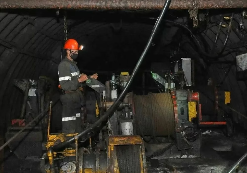
Large three-phase AC motors drove continuous-duty equipment (conveyor systems, pump stations, ventilation fans) with straightforward on/off control via contactor switches. The control circuits were simple, the equipment was robust and forgiving of electrical noise, and cable specifications focused purely on mechanical durability and basic electrical protection. Modern underground mining operations operate in a fundamentally different electrical environment. Variable frequency drives (VFDs) regulate motor speeds to match load requirements, reducing energy consumption and extending equipment life. Programmable logic controllers (PLCs) and distributed control systems (DCS) automate equipment sequencing and mine ventilation. Wireless monitoring systems track equipment health, environmental conditions, and safety parameters. The mine's electrical environment has become as electrically complex as an industrial manufacturing facility, except that everything must operate underground in the presence of conductive dust, moisture, and metallic ore particles that create unintended current paths and electromagnetic noise sources.

零下40℃也能高效防火?飞纯风力发电专用电缆通过俄罗斯 FSC 安全认证

严寒地区的风力发电项目通常位于高纬度、高海拔、草原、山地、海岸或开阔荒漠。风机长期暴露在低温、强风、冰雪、紫外线和温差循环中,塔筒内部还存在扭转、振动、摆动和持续运行带来的电缆疲劳。对于风电电缆而言,零下 40℃ 环境下仍能保持稳定运行,需要的不只是材料“不会冻裂”,而是电气、机械和消防性能在低温条件下保持协同。 飞纯风力发电专用电缆面向这种严苛工况,通过俄罗斯 FSC 安全认证,形成“低温可靠 + 防火合规 + 风机动态适配”的产品价值。对于寒区风电场、俄罗斯风电项目、北方高寒区域和出口风机配套项目,这种认证和性能组合具有很强的工程意义。
Feichun BASKET SPREADER 740 (YSLTOE): Advanced Salt-Spray-Resistant Port Crane Control Cable for Hoisting Cages and Spreader Festoon Systems (300/500 V Nominal, 310/550 V Maximum AC, 410/825 V Maximum DC, 2 kV Test Voltage, −20 to +60°C Bidirectional Temperature Envelope for Both Fixed Laying and Flexible Application, +70°C Continuous Conductor Operating Temperature, +150°C Short-Circuit Conductor Limit, Proprietary Aramide Yarn Central Unit Reinforced with Embedded Lead Core for Combined Tensile Anchor and Vibration-Damping Mass Distribution, Polyurethane Outer Sheath PUR Type 11YM1 with Black RAL 9005-Equivalent Coloration Engineered for Superior Hydrolysis Resistance and Salt-Mist Corrosion Suppression, PVC Type YI2 Core Insulation, Class 6 Ultra-Flexible Bare Red Copper Conductor per IEC 60228 and DIN VDE 0295, EN 50334-Compliant Black Cores with Sequential Numbering Plus Green/Yellow Protective Earth, Bundle-Plus-Central-Unit Stranding Geometry with Non-Woven Tape Wrapping per Bundle and Overall, 50-Meter Continuous Vertical Suspension Capability, 160 m/min Maximum Operational Speed for Crane Festoon and Hoisting Cage Applications, ±25°/m Torsion Resistan

BASKET SPREADER 740 (YSLTOE)

Feichun BASKET SPREADER 740 (YSLTOE): Advanced Salt-Spray-Resistant Port Crane Control Cable for Hoisting Cages and Spreader Festoon Systems (300/500 V Nominal, 310/550 V Maximum AC, 410/825 V Maximum DC, 2 kV Test Voltage, −20 to +60°C Bidirectional Temperature Envelope for Both Fixed Laying and Flexible Application, +70°C Continuous Conductor Operating Temperature, +150°C Short-Circuit Conductor Limit, Proprietary Aramide Yarn Central Unit Reinforced with Embedded Lead Core for Combined Tensile Anchor and Vibration-Damping Mass Distribution, Polyurethane Outer Sheath PUR Type 11YM1 with Black RAL 9005-Equivalent Coloration Engineered for Superior Hydrolysis Resistance and Salt-Mist Corrosion Suppression, PVC Type YI2 Core Insulation, Class 6 Ultra-Flexible Bare Red Copper Conductor per IEC 60228 and DIN VDE 0295, EN 50334-Compliant Black Cores with Sequential Numbering Plus Green/Yellow Protective Earth, Bundle-Plus-Central-Unit Stranding Geometry with Non-Woven Tape Wrapping per Bundle and Overall, 50-Meter Continuous Vertical Suspension Capability, 160 m/min Maximum Operational Speed for Crane Festoon and Hoisting Cage Applications, ±25°/m Torsion Resistan
PANZERFLEX-S / ELX (N)TSCGEWÖU: Micro-Filtered HEPR Rubber Insulation Chemistry, Red Polychloroprene (PCP) 5GM5-Grade Salt-Fog Resistant Outer Sheath, Semiconductive Field-Control Architecture, High-Flexibility Design for Port Reeling & Festoon Systems, Split Protective Earth Cores, Anti-Torsion Textile Braid, 3.6/6 kV through 12/20 kV Voltage Classes (18/30 kV Available on Request), Thermal Stability (-30°C to +90°C Flexible Operation), Environmental Durability (Salt-Fog, UV, Oil, Moisture Resistance), STS Container Cranes, Ship-to-Shore Cranes, Ship Loaders, Stacker Reclaimers, Excavators, Cable Reel Systems, Festoon Systems, High-Speed Reeling, Comparative Analysis vs. TENAX TTS and PROTOLON(SMK) Designs, European Port Terminal Field Performance Validation, and Complete Technical Specification Guidance

PANZERFLEX-S / ELX (N)TSCGEWÖU

PANZERFLEX-S / ELX (N)TSCGEWÖU: Micro-Filtered HEPR Rubber Insulation Chemistry, Red Polychloroprene (PCP) 5GM5-Grade Salt-Fog Resistant Outer Sheath, Semiconductive Field-Control Architecture, High-Flexibility Design for Port Reeling & Festoon Systems, Split Protective Earth Cores, Anti-Torsion Textile Braid, 3.6/6 kV through 12/20 kV Voltage Classes (18/30 kV Available on Request), Thermal Stability (-30°C to +90°C Flexible Operation), Environmental Durability (Salt-Fog, UV, Oil, Moisture Resistance), STS Container Cranes, Ship-to-Shore Cranes, Ship Loaders, Stacker Reclaimers, Excavators, Cable Reel Systems, Festoon Systems, High-Speed Reeling, Comparative Analysis vs. TENAX TTS and PROTOLON(SMK) Designs, European Port Terminal Field Performance Validation, and Complete Technical Specification Guidance
Full technical breakdown Lapp ÖLFLEX CRANE NSHTÖU 0.6/1 kV (max 1.2 kV): specialized motorized drum cable for cranes (gantry, bridge, portal, jib) with extreme cold capability -25°C to -40°C dynamic. NSHTÖU per VDE 0250-814: N (normalized), S (hose-type), H (special elastomer), T (trommel/drum), Ö (oil-resistant), U (reinforced). Works at spool speeds up to 120 m/min in repeated flex. Core problem: standard neoprene outers become brittle below -25°C and crack during drum bending. Arctic version uses modified elastomer compound (5GM5-Arctic) with plasticizers that don't crystallize at sub-zero, ensures -40°C operation. Configuration 4G50: tinned Cu Cl.5, special EPR 3GI3 insulation, internal anti-skewing rubber extrusion, outer Arctic-grade neoprene or PUR. OD ~18–22 mm, weight ~0.85–1.1 kg/m, current ~250–280 A. Alternatives: (1) FeiChun NSHTÖU-Cold — Lapp equivalent with Arctic compound, -40°C dynamic, better price; (2) FeiChun PUR Reeling Cable — PUR sheath, -50°C capable, 15–20% lighter, preferred for Arctic/Siberia. Russian GOST alternatives (КГРПУ, КГЭЖ-ХЛ) require TU modification for drum application.

ÖLFLEX CRANE NSHTÖU Морозостойкий кабель для крановых барабанов: инженерия холода — FeiChun NSHTÖU-Cold и PUR Reeling Cable, аналог Lapp

Full technical breakdown Lapp ÖLFLEX CRANE NSHTÖU 0.6/1 kV (max 1.2 kV): specialized motorized drum cable for cranes (gantry, bridge, portal, jib) with extreme cold capability -25°C to -40°C dynamic. NSHTÖU per VDE 0250-814: N (normalized), S (hose-type), H (special elastomer), T (trommel/drum), Ö (oil-resistant), U (reinforced). Works at spool speeds up to 120 m/min in repeated flex. Core problem: standard neoprene outers become brittle below -25°C and crack during drum bending. Arctic version uses modified elastomer compound (5GM5-Arctic) with plasticizers that don’t crystallize at sub-zero, ensures -40°C operation. Configuration 4G50: tinned Cu Cl.5, special EPR 3GI3 insulation, internal anti-skewing rubber extrusion, outer Arctic-grade neoprene or PUR. OD ~18–22 mm, weight ~0.85–1.1 kg/m, current ~250–280 A. Alternatives: (1) FeiChun NSHTÖU-Cold — Lapp equivalent with Arctic compound, -40°C dynamic, better price; (2) FeiChun PUR Reeling Cable — PUR sheath, -50°C capable, 15–20% lighter, preferred for Arctic/Siberia. Russian GOST alternatives (КГРПУ, КГЭЖ-ХЛ) require TU modification for drum application.
Full technical breakdown Prysmian (Draka) CORDAFLEX SME — Arctic modification of (N)TSCGEWÖU 6/10 kV motorized drum cable, designed for reeling at extreme cold to -40°C. Standard rubber/PUR at such temperatures becomes brittle as glass and cracks on first guide roller bend. SME solves this with three engineering innovations: (1) cold-resistant polychloroprene outer sheath "5GM5 Arctic blend" with non-freezing plasticizers maintaining elasticity at -40°C; (2) reinforced tensile strength 20 N/mm² (vs standard 15), compensating lubricant thickening in drum gearboxes and jerks during winter starts; (3) micro-filtered EPR compound 3GI3 maintaining dielectric properties at -40°C without cracking. Temp range -40°C to +80°C (flexing), -50°C to +80°C (fixed). Winding speed up to 120 m/min. VDE 0250-813 (SME modification). Two import substitution paths: (1) FeiChun NTSCGEWÖU-Cold — certified equivalent with Arctic additives for Siberia/Canada; (2) КГЭ-ХЛ 6 kV — Russian GOST to -60°C, but mechanically weaker than SME and lower winding speeds.

Характеристики CORDAFLEX (SME): экскаваторный кабель (N)TSCGEWÖU 6/10kV для наматывания при -40°C — арктическая серия и аналог FeiChun

Full technical breakdown Prysmian (Draka) CORDAFLEX SME — Arctic modification of (N)TSCGEWÖU 6/10 kV motorized drum cable, designed for reeling at extreme cold to -40°C. Standard rubber/PUR at such temperatures becomes brittle as glass and cracks on first guide roller bend. SME solves this with three engineering innovations: (1) cold-resistant polychloroprene outer sheath “5GM5 Arctic blend” with non-freezing plasticizers maintaining elasticity at -40°C; (2) reinforced tensile strength 20 N/mm² (vs standard 15), compensating lubricant thickening in drum gearboxes and jerks during winter starts; (3) micro-filtered EPR compound 3GI3 maintaining dielectric properties at -40°C without cracking. Temp range -40°C to +80°C (flexing), -50°C to +80°C (fixed). Winding speed up to 120 m/min. VDE 0250-813 (SME modification). Two import substitution paths: (1) FeiChun NTSCGEWÖU-Cold — certified equivalent with Arctic additives for Siberia/Canada; (2) КГЭ-ХЛ 6 kV — Russian GOST to -60°C, but mechanically weaker than SME and lower winding speeds.
Full technical breakdown Prysmian (Draka) CORDAFLEX SMK series — the "gold standard" for motorized cable reels on portal cranes, stacker-reclaimers, and excavators. Marking (N)TSCGEWÖU, cross-section 3×150+3×25/3, voltage 6/10 kV (max operating 7.2/12 kV). Weight 6.5+ tons/km, OD 58–64 mm, current rating ~425 A (30°C open air), short-circuit ~21.4 kA (1s). Key SMK distinction: built-in anti-torsion guard — reinforced inner sheath with high-strength synthetic braid (aramid/Kevlar) compensating torque from guide rollers and multi-layer winding at speeds up to 120–160 m/min. Without this, standard cables corkscrew and fail on motor drums. Construction: 3×150 mm² tinned copper class 5, split earth 3×(25/3)=3×8.33 mm², EPR insulation type 3GI3, extruded semiconducting screens, polychloroprene (5GM5) or special elastomer outer sheath. Temp -25°C to +80°C standard, Arctic to -40°C. Russian market: GOST КГЭ/КГЭ-ХЛ cables are trailing-only (no anti-torsion) and fail on motor drums. Anhui Feichun offers certified drop-in replacement FC-CORDAFLEX-SMK with integrated aramid anti-torsion braid per VDE, CCV vulcanization, and OD adaptation for existing drums and cable-layers.

Аналог CORDAFLEX (SMK): барабанный кабель (N)TSCGEWÖU 3×150+3×25/3 6/10kV в России — антиторсионная защита, 425 А, замена FeiChun Cable

Full technical breakdown Prysmian (Draka) CORDAFLEX SMK series — the “gold standard” for motorized cable reels on portal cranes, stacker-reclaimers, and excavators. Marking (N)TSCGEWÖU, cross-section 3×150+3×25/3, voltage 6/10 kV (max operating 7.2/12 kV). Weight 6.5+ tons/km, OD 58–64 mm, current rating ~425 A (30°C open air), short-circuit ~21.4 kA (1s). Key SMK distinction: built-in anti-torsion guard — reinforced inner sheath with high-strength synthetic braid (aramid/Kevlar) compensating torque from guide rollers and multi-layer winding at speeds up to 120–160 m/min. Without this, standard cables corkscrew and fail on motor drums. Construction: 3×150 mm² tinned copper class 5, split earth 3×(25/3)=3×8.33 mm², EPR insulation type 3GI3, extruded semiconducting screens, polychloroprene (5GM5) or special elastomer outer sheath. Temp -25°C to +80°C standard, Arctic to -40°C. Russian market: GOST КГЭ/КГЭ-ХЛ cables are trailing-only (no anti-torsion) and fail on motor drums. Anhui Feichun offers certified drop-in replacement FC-CORDAFLEX-SMK with integrated aramid anti-torsion braid per VDE, CCV vulcanization, and OD adaptation for existing drums and cable-layers.
Full decoding of RTS (Robotic/Torsion Standard) conductor class for ultra-fine stranded copper: wire diameter ≤0.10–0.15 mm, 5–10M+ flex cycles, min bend radius 5×OD dynamic, travel speed up to 10 m/s in drag chains. Letter-by-letter decoding of (N)TSCGEWÖU (also searched as NTSCGEWOEU or NTSCGEWOU). Comparison Class 5 → Class 6 → RTS/special. Construction: short-pitch bunch-in-bunch stranding, pressure-extruded sheath, central tension member. Why Class 5 fails in energy chains: bird-caging, wire fracture, contact loss. Sample spec 4G1.5 mm² RTS (300/500 V). Pricing: Igus €8–14/m, Lapp €6–12/m vs Feichun FC-RTS €2.5–5.5/m (45–60% savings). 5-year TCO for 6-axis robot cells. EAC, GOST-R, CE, UL certified.

Проводник медный сверхтонкий многожильный, класс „RTS”: почему он лучше IEC 60228 / DIN VDE 0295 Класс 5

Full decoding of RTS (Robotic/Torsion Standard) conductor class for ultra-fine stranded copper: wire diameter ≤0.10–0.15 mm, 5–10M+ flex cycles, min bend radius 5×OD dynamic, travel speed up to 10 m/s in drag chains. Letter-by-letter decoding of (N)TSCGEWÖU (also searched as NTSCGEWOEU or NTSCGEWOU). Comparison Class 5 → Class 6 → RTS/special. Construction: short-pitch bunch-in-bunch stranding, pressure-extruded sheath, central tension member. Why Class 5 fails in energy chains: bird-caging, wire fracture, contact loss. Sample spec 4G1.5 mm² RTS (300/500 V). Pricing: Igus €8–14/m, Lapp €6–12/m vs Feichun FC-RTS €2.5–5.5/m (45–60% savings). 5-year TCO for 6-axis robot cells. EAC, GOST-R, CE, UL certified.
This distinction is not academic. Every year, mining operations, port facilities, and industrial plants experience cable failures because an engineer or procurement team specified a trailing cable where a reeling cable was needed, or vice versa. The cables may share similar voltage ratings, conductor sizes, and even visual appearance—but they are engineered to solve fundamentally different mechanical problems. A trailing cable installed on a reeling drum will fatigue and fail within weeks. A reeling cable dragged across a mine floor will be cut, crushed, and destroyed within days. Understanding the engineering rationale behind each cable type is essential for anyone involved in cable specification, procurement, or installation for mining and heavy industrial applications. 这一区别绝非学术问题。每年都有矿山、港口和工业厂房因在需要卷筒电缆的场合错误使用了拖曳电缆(或反之)而发生电缆失效。两种电缆可能共享相似的电压等级、导体截面甚至外观——但它们的工程设计解决的是截然不同的机械问题。将拖曳电缆安装在卷筒上会在数周内导致疲劳断裂;将卷筒电缆在矿井地面拖拽会在数天内被切割和压碎。 This article provides the complete engineering foundation for understanding the differences. It is written for electrical engineers, mine electrical supervisors, procurement specialists, and equipment operators who must select the correct cable type for their specific application. Every comparison, every specification value, and every material choice described below is grounded in the physical reality of how these cables operate—and fail—in the field.

Reeling Cable vs Trailing Cable: Complete Engineering Comparison for Mining & Heavy Industry

This distinction is not academic. Every year, mining operations, port facilities, and industrial plants experience cable failures because an engineer or procurement team specified a trailing cable where a reeling cable was needed, or vice versa. The cables may share similar voltage ratings, conductor sizes, and even visual appearance—but they are engineered to solve fundamentally different mechanical problems. A trailing cable installed on a reeling drum will fatigue and fail within weeks. A reeling cable dragged across a mine floor will be cut, crushed, and destroyed within days. Understanding the engineering rationale behind each cable type is essential for anyone involved in cable specification, procurement, or installation for mining and heavy industrial applications. 这一区别绝非学术问题。每年都有矿山、港口和工业厂房因在需要卷筒电缆的场合错误使用了拖曳电缆(或反之)而发生电缆失效。两种电缆可能共享相似的电压等级、导体截面甚至外观——但它们的工程设计解决的是截然不同的机械问题。将拖曳电缆安装在卷筒上会在数周内导致疲劳断裂;将卷筒电缆在矿井地面拖拽会在数天内被切割和压碎。 This article provides the complete engineering foundation for understanding the differences. It is written for electrical engineers, mine electrical supervisors, procurement specialists, and equipment operators who must select the correct cable type for their specific application. Every comparison, every specification value, and every material choice described below is grounded in the physical reality of how these cables operate—and fail—in the field.
Joy Shuttle Car Operating Cycle: Joy Global's shuttle cars are core materials transport vehicles in underground coal mines. A typical operational cycle involves: (1) Advancing into mine face (unreeling cable under constant speed tension), (2) Loading ore/waste into bucket, (3) Sharp turns and direction changes (rapid torsional and bending stress), (4) Reversing to dump point (rapid cable reeling, highest tension conditions), (5) Return to face under load (sustained tension, speeds 50–100 m/min). A single shift can involve 80–120 complete cycles. Joy Global穿梭车是地下煤矿的核心运输工具。典型运行周期包括:(1)推进到矿面(在恒定速度张力下放线),(2)装载矿石/废料,(3)急转弯和方向改变(快速扭转和弯曲应力),(4)倒车至卸点(快速收线,最高张力条件),(5)负载返回(持续张力,速度50-100 m/min)。单班可完成80-120个完整周期。 Cable Stress Combination: Unlike stationary installations where cables experience steady-state thermal and electrical stress, shuttle car cables experience: (1) Cyclic tensile loading (alternating between low idle tension and high reeling tension), (2) Torsional twisting during turns (multiple revolutions per shift), (3) Sharp bending around reel drum edges (radius-limited deflection), (4) Thermal cycling (ambient underground temperature 15–25°C during operation, cold surface storage -5°C to -20°C).

Joy Shuttle Car Tension Ratings: Maximum Safe Pulling Load for Type 275 3.3/3.3kV 3x50mm² Cables

Joy Shuttle Car Operating Cycle: Joy Global’s shuttle cars are core materials transport vehicles in underground coal mines. A typical operational cycle involves: (1) Advancing into mine face (unreeling cable under constant speed tension), (2) Loading ore/waste into bucket, (3) Sharp turns and direction changes (rapid torsional and bending stress), (4) Reversing to dump point (rapid cable reeling, highest tension conditions), (5) Return to face under load (sustained tension, speeds 50–100 m/min). A single shift can involve 80–120 complete cycles. Joy Global穿梭车是地下煤矿的核心运输工具。典型运行周期包括:(1)推进到矿面(在恒定速度张力下放线),(2)装载矿石/废料,(3)急转弯和方向改变(快速扭转和弯曲应力),(4)倒车至卸点(快速收线,最高张力条件),(5)负载返回(持续张力,速度50-100 m/min)。单班可完成80-120个完整周期。 Cable Stress Combination: Unlike stationary installations where cables experience steady-state thermal and electrical stress, shuttle car cables experience: (1) Cyclic tensile loading (alternating between low idle tension and high reeling tension), (2) Torsional twisting during turns (multiple revolutions per shift), (3) Sharp bending around reel drum edges (radius-limited deflection), (4) Thermal cycling (ambient underground temperature 15–25°C during operation, cold surface storage -5°C to -20°C).
The Dangerous Misconception: When Indonesian coal contractors (PAMA, BUMA, Thiess Indonesia) begin sourcing cable replacements for aging Olex (Nexans) systems, there is a common but catastrophic confusion: conflating Type 260 (pliable armoured feeder cable) with shuttle car trailing cables. This error, if executed in procurement, will result in: (1) Physical incompatibility with shuttle car reels, (2) Equipment damage within days of deployment, (3) Potential explosive electrical failures underground, (4) Massive operational downtime and safety hazards.

Indonesian Coal Contractors: Type 260 vs Type 275—Critical Clarification for Drop-in Shuttle Car Cable Equivalents

The Dangerous Misconception: When Indonesian coal contractors (PAMA, BUMA, Thiess Indonesia) begin sourcing cable replacements for aging Olex (Nexans) systems, there is a common but catastrophic confusion: conflating Type 260 (pliable armoured feeder cable) with shuttle car trailing cables. This error, if executed in procurement, will result in: (1) Physical incompatibility with shuttle car reels, (2) Equipment damage within days of deployment, (3) Potential explosive electrical failures underground, (4) Massive operational downtime and safety hazards.
Standards Clarification: AS/NZS 1972 defines Type 9 explicitly as a gas non-transmission cable, specifically engineered for flameproof (Ex d) electrical equipment enclosures. Type 9 cables are typically small-diameter, multi-core control or monitoring cables (0.5 mm², 1.5 mm², etc.)—never large power conductors like 3×95 mm². 标准澄清:AS/NZS 1972明确定义Type 9为防气体传输电缆,特别是为了防爆(Ex d)电气设备外壳而设计。Type 9电缆通常是小径、多芯的控制或监测电缆(0.5 mm²、1.5 mm²等)——绝对不是大功率导体如3×95 mm²。 Why the Confusion? The numbering system in AS/NZS 1972 progresses from Type 1 (fixed installation) through Type 8 (vertical shaft DWA cables). Type 9's designation comes last but reflects a specialized application (flameproof enclosures) rather than advancement in power capacity. Engineers sometimes assume higher type numbers equal higher voltage/current capacity—this assumption is incorrect for Type 9.

Tensile Load Limits: Calculating Maximum Suspension Depth for AS/NZS 1972 Mining Cables

Standards Clarification: AS/NZS 1972 defines Type 9 explicitly as a gas non-transmission cable, specifically engineered for flameproof (Ex d) electrical equipment enclosures. Type 9 cables are typically small-diameter, multi-core control or monitoring cables (0.5 mm², 1.5 mm², etc.)—never large power conductors like 3×95 mm². 标准澄清:AS/NZS 1972明确定义Type 9为防气体传输电缆,特别是为了防爆(Ex d)电气设备外壳而设计。Type 9电缆通常是小径、多芯的控制或监测电缆(0.5 mm²、1.5 mm²等)——绝对不是大功率导体如3×95 mm²。 Why the Confusion? The numbering system in AS/NZS 1972 progresses from Type 1 (fixed installation) through Type 8 (vertical shaft DWA cables). Type 9’s designation comes last but reflects a specialized application (flameproof enclosures) rather than advancement in power capacity. Engineers sometimes assume higher type numbers equal higher voltage/current capacity—this assumption is incorrect for Type 9.Standards Clarification: AS/NZS 1972 defines Type 9 explicitly as a gas non-transmission cable, specifically engineered for flameproof (Ex d) electrical equipment enclosures. Type 9 cables are typically small-diameter, multi-core control or monitoring cables (0.5 mm², 1.5 mm², etc.)—never large power conductors like 3×95 mm². 标准澄清:AS/NZS 1972明确定义Type 9为防气体传输电缆,特别是为了防爆(Ex d)电气设备外壳而设计。Type 9电缆通常是小径、多芯的控制或监测电缆(0.5 mm²、1.5 mm²等)——绝对不是大功率导体如3×95 mm²。 Why the Confusion? The numbering system in AS/NZS 1972 progresses from Type 1 (fixed installation) through Type 8 (vertical shaft DWA cables). Type 9’s designation comes last but reflects a specialized application (flameproof enclosures) rather than advancement in power capacity. Engineers sometimes assume higher type numbers equal higher voltage/current capacity—this assumption is incorrect for Type 9.
ThyssenKrupp manufactures some of the world's largest bulk material handling equipment, including stacker reclaimers that can handle thousands of tons of material (iron ore, coal, phosphate) daily in open-pit mining and port environments. These massive machines—often exceeding 50+ meters in height and 300+ meters in length—require electrical power in the megawatt range (5–15 MW typical for large stacker reclaimers) delivered via heavy-duty reeling cables that can withstand continuous deployment and rapid retraction. 蒂森克虏伯制造世界上一些最大的散货搬运设备,包括能够每天处理数千吨物料(铁矿石、煤炭、磷酸盐)的堆取料机,在露天采矿和港口环境中运行。这些庞大机器——通常超过50米高、300多米长——需要兆瓦级电力(典型大型堆取料机5-15兆瓦),通过能够承受连续部署和快速收回的重型卷筒电缆传输。 System Architecture: A large stacker reclaimer comprises: (1) main structure (steel boom, buckets, conveyor systems), (2) electric motors (ranging from 300 kW to several megawatts), (3) reeling drum system with cable capacity 1000+ meters, (4) high-speed gearbox and transmission system enabling 120–160 m/min travel speed. The electrical power system typically operates at 6.6kV nominal (sometimes 11kV for the largest systems), with power distribution from the mine substation to the mobile reclaimer through trailing cables that must flex continuously.

ThyssenKrupp Stacker Reclaimers: Matching VDE Mechanicals with 6.6/6.6kV Australian Voltages

ThyssenKrupp manufactures some of the world’s largest bulk material handling equipment, including stacker reclaimers that can handle thousands of tons of material (iron ore, coal, phosphate) daily in open-pit mining and port environments. These massive machines—often exceeding 50+ meters in height and 300+ meters in length—require electrical power in the megawatt range (5–15 MW typical for large stacker reclaimers) delivered via heavy-duty reeling cables that can withstand continuous deployment and rapid retraction. 蒂森克虏伯制造世界上一些最大的散货搬运设备,包括能够每天处理数千吨物料(铁矿石、煤炭、磷酸盐)的堆取料机,在露天采矿和港口环境中运行。这些庞大机器——通常超过50米高、300多米长——需要兆瓦级电力(典型大型堆取料机5-15兆瓦),通过能够承受连续部署和快速收回的重型卷筒电缆传输。 System Architecture: A large stacker reclaimer comprises: (1) main structure (steel boom, buckets, conveyor systems), (2) electric motors (ranging from 300 kW to several megawatts), (3) reeling drum system with cable capacity 1000+ meters, (4) high-speed gearbox and transmission system enabling 120–160 m/min travel speed. The electrical power system typically operates at 6.6kV nominal (sometimes 11kV for the largest systems), with power distribution from the mine substation to the mobile reclaimer through trailing cables that must flex continuously.
RHEYFIRM® is Nexans' premium line of flexible medium-voltage reeling cables specifically engineered for the extreme mechanical and environmental stresses of port machinery (STS cranes, automated stacker-reclaimers) and mining equipment (continuous dragline cables, mobile crusher power systems). Unlike fixed installation cables that remain stationary throughout their service life, reeling cables experience constant dynamic stress—deploying and retracting hundreds to thousands of times over their operational life. This continuous reeling duty subjects the cable to millions of bending cycles, sustained tensile loads, electromagnetic stress, salt spray corrosion, intense ultraviolet radiation, and temperature extremes far exceeding what conventional industrial cables are designed to tolerate. The physical diameter of a reeling cable is not simply a matter of aesthetics or standardization—it directly affects how much cable can fit on a physical drum of fixed dimensions. Consider a stacker-reclaimer with an existing cable drum that has a fixed flange width (say, 1,200 millimeters) and a fixed core diameter (say, 400 millimeters). The amount of cable that can be wound onto this drum depends on how tightly the cable packs around the core. A cable with a 59-millimeter outer diameter will create a larger spiral as it is wound layer by layer, limiting the total cable length to perhaps 600 meters. That same physical drum, if fitted with a 55.8-millimeter diameter cable, creates a tighter spiral and accommodates perhaps 750 meters of cable—a 25 percent increase in usable length with zero change to the physical equipment. For equipment where travel distance requirements have increased due to terminal expansion or operational upgrades, this diameter optimization can mean the difference between being able to extend operations and being forced into an expensive drum replacement project costing hundreds of thousands of dollars.

RHEYFIRM® (RS) vs. RHEYFIRM® (RTS): When to Choose the “Reduced Diameter” Version for Space-Constrained Reels

RHEYFIRM® is Nexans’ premium line of flexible medium-voltage reeling cables specifically engineered for the extreme mechanical and environmental stresses of port machinery (STS cranes, automated stacker-reclaimers) and mining equipment (continuous dragline cables, mobile crusher power systems). Unlike fixed installation cables that remain stationary throughout their service life, reeling cables experience constant dynamic stress—deploying and retracting hundreds to thousands of times over their operational life. This continuous reeling duty subjects the cable to millions of bending cycles, sustained tensile loads, electromagnetic stress, salt spray corrosion, intense ultraviolet radiation, and temperature extremes far exceeding what conventional industrial cables are designed to tolerate. The physical diameter of a reeling cable is not simply a matter of aesthetics or standardization—it directly affects how much cable can fit on a physical drum of fixed dimensions. Consider a stacker-reclaimer with an existing cable drum that has a fixed flange width (say, 1,200 millimeters) and a fixed core diameter (say, 400 millimeters). The amount of cable that can be wound onto this drum depends on how tightly the cable packs around the core. A cable with a 59-millimeter outer diameter will create a larger spiral as it is wound layer by layer, limiting the total cable length to perhaps 600 meters. That same physical drum, if fitted with a 55.8-millimeter diameter cable, creates a tighter spiral and accommodates perhaps 750 meters of cable—a 25 percent increase in usable length with zero change to the physical equipment. For equipment where travel distance requirements have increased due to terminal expansion or operational upgrades, this diameter optimization can mean the difference between being able to extend operations and being forced into an expensive drum replacement project costing hundreds of thousands of dollars.
(N)TSCGEWÖU 3x120+3x70/3 12/20kV cable is the correct choice for most tunnel boring machine main cutterhead power supplies operating at medium voltage with cutterhead thrust loads in the range of 8,000 to 12,000 kilonewtons, featuring three 120 mm² phase conductors providing approximately 350 to 380 amperes current capacity in free-air installation at 30°C ambient and 90°C conductor operating temperature. The cable's nominal outer diameter is 73 to 81 millimeters, with total weight of approximately 9,800 to 10,500 kilograms per kilometer, making it manageable for most standard cable spools while still providing sufficient conductor cross-section to limit voltage drop to acceptable levels over tunnel distances extending several kilometers. The cable features Class 5 tinned copper conductors engineered for fatigue resistance in continuously flexing applications, EPR insulation maintaining exceptional thermal stability even when subjected to the 90°C conductor temperature that results from high-current excavation duty, semi-conductive shielding layers that uniformly distribute electric stress and prevent partial discharge initiation in the high-voltage environment, and a heavy-duty CPE jacket providing abrasion resistance in the confined underground spaces where the cable is routed. However, the critical distinction between simply selecting a cable model and properly sizing a cable for your specific tunnel boring installation lies in understanding the difference between the cable's theoretical free-air current capacity and its actual safe operating current when coiled on a cable drum—a difference that can reduce safe current by 30 to 50 percent depending on the spooling configuration. For tunnel boring machines operating in continental European or Asian tunneling projects with tunnel lengths of 5 to 15 kilometers and cutterhead thrust loads in the moderate to high range, the 3x120+3x70/3 12/20kV cable provides excellent balance between current capacity, voltage drop performance, mechanical durability, and cost. However, for shorter tunnels where voltage drop is not a concern, smaller conductor sizes (such as 3x95 mm²) may provide adequate performance at lower material cost, while for exceptionally long tunnels or extremely high thrust conditions, larger sizes (such as 3x150 mm² or 3x185 mm²) become necessary to maintain safe operating currents and acceptable voltage drop. Proper cable sizing requires engineering analysis specific to your tunnel length, expected cutterhead current demand, acceptable voltage drop limits, available cable drum diameters, and operational duty cycle.

Tunnel Boring Machines (TBM): Sizing (N)TSCGEWÖU 3×120+3×70/3 12/20kV for the Main Cutterhead Power Supply

(N)TSCGEWÖU 3×120+3×70/3 12/20kV cable is the correct choice for most tunnel boring machine main cutterhead power supplies operating at medium voltage with cutterhead thrust loads in the range of 8,000 to 12,000 kilonewtons, featuring three 120 mm² phase conductors providing approximately 350 to 380 amperes current capacity in free-air installation at 30°C ambient and 90°C conductor operating temperature. The cable’s nominal outer diameter is 73 to 81 millimeters, with total weight of approximately 9,800 to 10,500 kilograms per kilometer, making it manageable for most standard cable spools while still providing sufficient conductor cross-section to limit voltage drop to acceptable levels over tunnel distances extending several kilometers. The cable features Class 5 tinned copper conductors engineered for fatigue resistance in continuously flexing applications, EPR insulation maintaining exceptional thermal stability even when subjected to the 90°C conductor temperature that results from high-current excavation duty, semi-conductive shielding layers that uniformly distribute electric stress and prevent partial discharge initiation in the high-voltage environment, and a heavy-duty CPE jacket providing abrasion resistance in the confined underground spaces where the cable is routed. However, the critical distinction between simply selecting a cable model and properly sizing a cable for your specific tunnel boring installation lies in understanding the difference between the cable’s theoretical free-air current capacity and its actual safe operating current when coiled on a cable drum—a difference that can reduce safe current by 30 to 50 percent depending on the spooling configuration. For tunnel boring machines operating in continental European or Asian tunneling projects with tunnel lengths of 5 to 15 kilometers and cutterhead thrust loads in the moderate to high range, the 3×120+3×70/3 12/20kV cable provides excellent balance between current capacity, voltage drop performance, mechanical durability, and cost. However, for shorter tunnels where voltage drop is not a concern, smaller conductor sizes (such as 3×95 mm²) may provide adequate performance at lower material cost, while for exceptionally long tunnels or extremely high thrust conditions, larger sizes (such as 3×150 mm² or 3×185 mm²) become necessary to maintain safe operating currents and acceptable voltage drop. Proper cable sizing requires engineering analysis specific to your tunnel length, expected cutterhead current demand, acceptable voltage drop limits, available cable drum diameters, and operational duty cycle.
Type SHD-GC 3/C #1 AWG 8kV trailing cable has a DC resistance of approximately 0.161 ohms per kilometer measured at the reference temperature of 20°C (68°F). This DC resistance value represents the pure ohmic resistance of the copper conductor when direct current flows through it—a condition that occurs in short-circuit analysis and DC testing procedures. However, when this same cable carries the alternating current typical of mining equipment operations (at the standard operating temperature of 90°C), the AC resistance increases to approximately 0.363 ohms per kilometer due to the combined effects of temperature rise and skin effect phenomena. The substantial difference between 0.161 Ω/km (DC, 20°C) and 0.363 Ω/km (AC, 90°C)—more than a 2.25 times increase—demonstrates a critical principle that engineers must account for in real-world voltage drop calculations: laboratory DC resistance values are not directly applicable to field voltage drop analysis. The cable features three 107.2 mm² (1 AWG equivalent) phase conductors of Class 5 tinned copper, with an additional ground-check conductor for continuous monitoring of cable integrity during operation, an outer diameter of approximately 53–58 mm, and a total weight of approximately 6,200–6,800 kg/km. Understanding both the DC baseline resistance and the elevated AC resistance at operating temperature is essential for accurately predicting voltage drop over long cable runs in open-pit mining operations where power distribution distances frequently exceed 500 meters.

Voltage Drop Calculation: Resistance (Ohms/km) for Type SHD-GC 3/C #1 AWG 8kV Trailing Cable

Type SHD-GC 3/C #1 AWG 8kV trailing cable has a DC resistance of approximately 0.161 ohms per kilometer measured at the reference temperature of 20°C (68°F). This DC resistance value represents the pure ohmic resistance of the copper conductor when direct current flows through it—a condition that occurs in short-circuit analysis and DC testing procedures. However, when this same cable carries the alternating current typical of mining equipment operations (at the standard operating temperature of 90°C), the AC resistance increases to approximately 0.363 ohms per kilometer due to the combined effects of temperature rise and skin effect phenomena. The substantial difference between 0.161 Ω/km (DC, 20°C) and 0.363 Ω/km (AC, 90°C)—more than a 2.25 times increase—demonstrates a critical principle that engineers must account for in real-world voltage drop calculations: laboratory DC resistance values are not directly applicable to field voltage drop analysis. The cable features three 107.2 mm² (1 AWG equivalent) phase conductors of Class 5 tinned copper, with an additional ground-check conductor for continuous monitoring of cable integrity during operation, an outer diameter of approximately 53–58 mm, and a total weight of approximately 6,200–6,800 kg/km. Understanding both the DC baseline resistance and the elevated AC resistance at operating temperature is essential for accurately predicting voltage drop over long cable runs in open-pit mining operations where power distribution distances frequently exceed 500 meters.
The straightforward answer to whether (N)TCEWÖU 3x95 cables can survive the constant ±100°/m torsional stress inside a wind tower nacelle is: yes, absolutely—this cable type is specifically engineered for exactly this application and has demonstrated performance exceeding two million torsion cycles without failure. The (N)TCEWÖU designation itself is not arbitrary—it explicitly identifies cables designed for wind turbine applications where continuous twisting from the yaw system is the defining operating condition. This cable type achieves torsion tolerance through a fundamentally different design philosophy than conventional cables. Rather than attempting to rigidly prevent any twisting through mechanical constraint, the (N)TCEWÖU accomplishes tolerance through materials science and cable construction that allows controlled slippage of conductors during rotation, distributing torsional stress evenly across all cable components and preventing the stress concentration that destroys conventional cables. Understanding how this engineering works requires studying the physics of torsion, examining why conventional cables fail under these conditions, and learning how (N)TCEWÖU's special construction mitigates each failure mechanism.

Wind Turbine Drip Loops: Can (N)TCEWÖU 3×95 survive the constant +/- 100°/m torsion inside a wind tower nacelle?

The straightforward answer to whether (N)TCEWÖU 3×95 cables can survive the constant ±100°/m torsional stress inside a wind tower nacelle is: yes, absolutely—this cable type is specifically engineered for exactly this application and has demonstrated performance exceeding two million torsion cycles without failure. The (N)TCEWÖU designation itself is not arbitrary—it explicitly identifies cables designed for wind turbine applications where continuous twisting from the yaw system is the defining operating condition. This cable type achieves torsion tolerance through a fundamentally different design philosophy than conventional cables. Rather than attempting to rigidly prevent any twisting through mechanical constraint, the (N)TCEWÖU accomplishes tolerance through materials science and cable construction that allows controlled slippage of conductors during rotation, distributing torsional stress evenly across all cable components and preventing the stress concentration that destroys conventional cables. Understanding how this engineering works requires studying the physics of torsion, examining why conventional cables fail under these conditions, and learning how (N)TCEWÖU’s special construction mitigates each failure mechanism.
The continuous ampacity of (N)TSCGEWÖU 3x120+3x70/3 12/20kV flexible reeling cable is 360 amperes when operating as a single conductor run in free air at the reference condition of 30°C ambient temperature and 90°C conductor operating temperature according to VDE 0250-813 and DIN VDE 0298-4 standards. For tunnel boring machine cutterhead power supply applications where the cable is installed in the constrained environment of a TBM backup gantry system—bundled alongside control cables, communication lines, and other power feeders—and subjected to frequent mechanical stress from dragging and reeling operations, the practical safe ampacity derates to approximately 260–285 amperes depending on specific installation geometry, tunnel temperature profile, and frequency of mechanical cycling. These two ampacity values represent the boundary between theoretical maximum current capacity and the practical operating limit for reliable power delivery to a 2–3 megawatt main cutterhead drive motor in a hard-rock tunneling or soft-ground excavation system. Understanding where these values come from and how they apply to specific TBM configurations is essential for preventing unexpected power loss to the cutterhead, which could force a full machine shutdown and result in schedule delays of weeks or months in confined underground construction.

TBM Cutterhead Power Supply: How to correctly size (N)TSCGEWÖU 3×120+3×70/3 12/20kV flexible reeling cable for tunnel boring machine main drive systems 

The continuous ampacity of (N)TSCGEWÖU 3×120+3×70/3 12/20kV flexible reeling cable is 360 amperes when operating as a single conductor run in free air at the reference condition of 30°C ambient temperature and 90°C conductor operating temperature according to VDE 0250-813 and DIN VDE 0298-4 standards. For tunnel boring machine cutterhead power supply applications where the cable is installed in the constrained environment of a TBM backup gantry system—bundled alongside control cables, communication lines, and other power feeders—and subjected to frequent mechanical stress from dragging and reeling operations, the practical safe ampacity derates to approximately 260–285 amperes depending on specific installation geometry, tunnel temperature profile, and frequency of mechanical cycling. These two ampacity values represent the boundary between theoretical maximum current capacity and the practical operating limit for reliable power delivery to a 2–3 megawatt main cutterhead drive motor in a hard-rock tunneling or soft-ground excavation system. Understanding where these values come from and how they apply to specific TBM configurations is essential for preventing unexpected power loss to the cutterhead, which could force a full machine shutdown and result in schedule delays of weeks or months in confined underground construction.
The dielectric constant of the 3GI3 elastomeric insulation used in (N)3GHSSYCY 3x150+3x25/3 cable is approximately 6.2 to 6.8 at standard reference frequency of 1 kHz, with typical measured value around 6.5 for new cable material. The insulation breakdown voltage (also called dielectric strength or withstand voltage) exceeds 30 kV when measured under controlled laboratory conditions on fresh cable samples with 8 mm insulation thickness, typically achieving 32–38 kV before electrical breakdown occurs.

Dielectric Constant Specs: What is the exact dielectric constant and insulation breakdown voltage for (N)3GHSSYCY 3×150+3×25/3 medium-voltage cable in long VFD motor runs? 

The dielectric constant of the 3GI3 elastomeric insulation used in (N)3GHSSYCY 3×150+3×25/3 cable is approximately 6.2 to 6.8 at standard reference frequency of 1 kHz, with typical measured value around 6.5 for new cable material. The insulation breakdown voltage (also called dielectric strength or withstand voltage) exceeds 30 kV when measured under controlled laboratory conditions on fresh cable samples with 8 mm insulation thickness, typically achieving 32–38 kV before electrical breakdown occurs.
The 1-second short-circuit current rating for an NSHTÖU-J 4G95 0.6/1kV low-voltage heavy-duty reeling cable is approximately 8,500 to 10,200 amperes when the cable is new and at reference condition (20°C conductor temperature, single conductor in free air, no mechanical stress or aging degradation).

Short-Circuit Rating: What is the 1-second short-circuit current for NSHTÖU-J 4G95 0.6/1kV heavy-duty reeling cable? 

The 1-second short-circuit current rating for an NSHTÖU-J 4G95 0.6/1kV low-voltage heavy-duty reeling cable is approximately 8,500 to 10,200 amperes when the cable is new and at reference condition (20°C conductor temperature, single conductor in free air, no mechanical stress or aging degradation).
The continuous current carrying capacity of an (N)TSCGEWÖU 3x50+3x25/3 12/20kV cable wound in three compacted layers on a standard industrial reel is approximately 85 to 110 amperes depending on ambient temperature, mechanical stress conditions, and reel cooling characteristics. This represents a significant reduction from the cable's reference rating of 202 amperes, which is established under ideal laboratory conditions (30°C ambient, single conductor run in free air, no mechanical tension or twisting). The dramatic derating from 202 A to 85–110 A reflects the thermal constraint imposed by the compact three-layer geometry, where the inner layers of wound cable are thermally insulated by outer layers, preventing efficient dissipation of I²R resistive losses to the surrounding environment. The cable features three 50 mm² Class 2 stranded tinned copper main power conductors and a symmetrical 3×25 mm² grounding conductor architecture (the "3+3" design), weighing approximately 1,850 kg/km of copper content and 3,550–3,650 kg/km total weight, with proven torsional twist resistance to ±100°/m and maximum tensile load capability of 3,000 newtons per phase conductor.

Derating Factors: Current carrying capacity of (N)TSCGEWÖU 3×50+3×25/3 12/20kV wound in 3 layers on a reel

The continuous current carrying capacity of an (N)TSCGEWÖU 3×50+3×25/3 12/20kV cable wound in three compacted layers on a standard industrial reel is approximately 85 to 110 amperes depending on ambient temperature, mechanical stress conditions, and reel cooling characteristics. This represents a significant reduction from the cable’s reference rating of 202 amperes, which is established under ideal laboratory conditions (30°C ambient, single conductor run in free air, no mechanical tension or twisting). The dramatic derating from 202 A to 85–110 A reflects the thermal constraint imposed by the compact three-layer geometry, where the inner layers of wound cable are thermally insulated by outer layers, preventing efficient dissipation of I²R resistive losses to the surrounding environment. The cable features three 50 mm² Class 2 stranded tinned copper main power conductors and a symmetrical 3×25 mm² grounding conductor architecture (the “3+3” design), weighing approximately 1,850 kg/km of copper content and 3,550–3,650 kg/km total weight, with proven torsional twist resistance to ±100°/m and maximum tensile load capability of 3,000 newtons per phase conductor.
(N)TSCGEWÖU 3x240+3x120/3 6/10kV ultra-large medium-voltage reeling cable weighs approximately 12,100 kg per kilometer (approximately 8,100 lbs per 1,000 feet), with the copper conductor content comprising approximately 8,064 kg/km of this total weight. The remaining approximately 4,036 kg/km (approximately 33.4% of total weight) consists of insulation materials (EPR), protective layers (bedding material, anti-torsion braid reinforcement), inner protective jacket, and the outer rubber sheath material. This extreme weight—roughly equivalent to a fully-loaded large truck per kilometer of cable—represents the cumulative consequence of the cable's enormous conductor cross-sections: three main phase conductors of 240 mm² each (totaling 720 mm² of copper for power carrying) plus three split earth conductors of 120 mm² each (totaling 360 mm² additional copper for grounding and load distribution). The 12,100 kg/km specification establishes the cable as one of the world's heaviest industrial power cables, comparable in weight only to cables serving ultra-massive applications such as deep-water offshore drilling umbilicals, gigantic bucket-wheel excavators, or electrified super-heavy mining draglines. Understanding this weight is not an academic exercise but rather a critical factor for project managers, procurement engineers, and logistics specialists, because the extreme weight directly determines shipping container capacity, handling equipment requirements at origin and destination ports, reel design specifications, and the total cost of ownership including transportation costs that can exceed 20–30% of the cable's material cost.

How Much Does (N)TSCGEWÖU 3×240+3×120/3 6/10kV Flexible Cable Weigh Per Kilometer?

(N)TSCGEWÖU 3×240+3×120/3 6/10kV ultra-large medium-voltage reeling cable weighs approximately 12,100 kg per kilometer (approximately 8,100 lbs per 1,000 feet), with the copper conductor content comprising approximately 8,064 kg/km of this total weight. The remaining approximately 4,036 kg/km (approximately 33.4% of total weight) consists of insulation materials (EPR), protective layers (bedding material, anti-torsion braid reinforcement), inner protective jacket, and the outer rubber sheath material. This extreme weight—roughly equivalent to a fully-loaded large truck per kilometer of cable—represents the cumulative consequence of the cable’s enormous conductor cross-sections: three main phase conductors of 240 mm² each (totaling 720 mm² of copper for power carrying) plus three split earth conductors of 120 mm² each (totaling 360 mm² additional copper for grounding and load distribution). The 12,100 kg/km specification establishes the cable as one of the world’s heaviest industrial power cables, comparable in weight only to cables serving ultra-massive applications such as deep-water offshore drilling umbilicals, gigantic bucket-wheel excavators, or electrified super-heavy mining draglines. Understanding this weight is not an academic exercise but rather a critical factor for project managers, procurement engineers, and logistics specialists, because the extreme weight directly determines shipping container capacity, handling equipment requirements at origin and destination ports, reel design specifications, and the total cost of ownership including transportation costs that can exceed 20–30% of the cable’s material cost.
(N)TSKCGEWÖU 3x150+3x25/3 3.6/6kV cable with split three-part earth conductor is approximately 65 mm (2.56 inches), with a standard tolerance window of ±3.0 mm producing a permissible range of 62.0–68.0 mm. The inner jacket (the intermediate protective layer between the insulation and outer sheath) typically has a nominal thickness of approximately 0.8–1.0 mm, contributing to overall diameter build-up but not typically measured as a separate "inner diameter" in engineering specifications because the inner jacket is not a defined outer boundary—it is a layer embedded within the cable structure. The outer jacket (the final thermosetting rubber compound layer) has a nominal thickness of approximately 2.5–3.0 mm, providing the cable's mechanical interface with the environment. The approximate total weight of this cable is 8,200 kg/km (5,510 lbs/1000 ft), with copper content approximately 4,560 kg/km. It features three 150 mm² Class 5 tinned copper main phase conductors, three strategically distributed 25/3 mm² split earth conductors for electromagnetic symmetry, a 3GI3 high-dielectric EPR insulation system rated for continuous 90°C operation, an anti-torsion braid reinforcement layer, and a 5GM5 thermosetting halogen-free outer sheath providing extreme abrasion and tear resistance.

What is the Inner and Outer Jacket Diameter of (N)TSKCGEWÖU 3×150+3×25/3 3.6/6kV Splittable Earth Cable?

(N)TSKCGEWÖU 3×150+3×25/3 3.6/6kV cable with split three-part earth conductor is approximately 65 mm (2.56 inches), with a standard tolerance window of ±3.0 mm producing a permissible range of 62.0–68.0 mm. The inner jacket (the intermediate protective layer between the insulation and outer sheath) typically has a nominal thickness of approximately 0.8–1.0 mm, contributing to overall diameter build-up but not typically measured as a separate “inner diameter” in engineering specifications because the inner jacket is not a defined outer boundary—it is a layer embedded within the cable structure. The outer jacket (the final thermosetting rubber compound layer) has a nominal thickness of approximately 2.5–3.0 mm, providing the cable’s mechanical interface with the environment. The approximate total weight of this cable is 8,200 kg/km (5,510 lbs/1000 ft), with copper content approximately 4,560 kg/km. It features three 150 mm² Class 5 tinned copper main phase conductors, three strategically distributed 25/3 mm² split earth conductors for electromagnetic symmetry, a 3GI3 high-dielectric EPR insulation system rated for continuous 90°C operation, an anti-torsion braid reinforcement layer, and a 5GM5 thermosetting halogen-free outer sheath providing extreme abrasion and tear resistance.
Nexans RHEYFIRM (RS) 12/20kV is a premium-tier medium-voltage reeling cable specifically engineered for high-speed, high-stress port machinery and industrial heavy-load applications. The cable's design reflects Nexans' deep expertise in marine and dockside equipment, incorporating proprietary RHEYCLEAN insulation chemistry and reinforced anti-torsion braid architecture that together enable reliable operation in environments where cable flexing occurs thousands of times per day at speeds exceeding 200 meters per minute. However, RHEYFIRM cables command premium pricing that reflects both their proven field performance and Nexans' brand positioning. For procurement teams managing large cable quantities, facing extended supply lead times, or constrained by budget limitations, the search for a functionally equivalent alternative is not a search for a compromise. Rather, it is a systematic evaluation of competing engineering approaches that achieve the same electrical safety, mechanical durability, and environmental resilience through different manufacturing philosophies. This guide addresses the practical reality that excellent medium-voltage reeling cables are manufactured by multiple established European and global suppliers. Helukabel (Germany), SAB Kabel (Germany), Prysmian (Italy/France), Feichun (China), and other manufacturers produce cables that meet or exceed RHEYFIRM's performance specifications while offering cost savings between 15–35%, faster regional delivery, or better availability for Asia-Pacific projects.

Cost-Effective Replacement for Nexans RHEYFIRM (RS) 3×50+3×25/3 12/20kV

Nexans RHEYFIRM (RS) 12/20kV is a premium-tier medium-voltage reeling cable specifically engineered for high-speed, high-stress port machinery and industrial heavy-load applications. The cable’s design reflects Nexans’ deep expertise in marine and dockside equipment, incorporating proprietary RHEYCLEAN insulation chemistry and reinforced anti-torsion braid architecture that together enable reliable operation in environments where cable flexing occurs thousands of times per day at speeds exceeding 200 meters per minute. However, RHEYFIRM cables command premium pricing that reflects both their proven field performance and Nexans’ brand positioning. For procurement teams managing large cable quantities, facing extended supply lead times, or constrained by budget limitations, the search for a functionally equivalent alternative is not a search for a compromise. Rather, it is a systematic evaluation of competing engineering approaches that achieve the same electrical safety, mechanical durability, and environmental resilience through different manufacturing philosophies. This guide addresses the practical reality that excellent medium-voltage reeling cables are manufactured by multiple established European and global suppliers. Helukabel (Germany), SAB Kabel (Germany), Prysmian (Italy/France), Feichun (China), and other manufacturers produce cables that meet or exceed RHEYFIRM’s performance specifications while offering cost savings between 15–35%, faster regional delivery, or better availability for Asia-Pacific projects.
NSHTÖU cables, this limit is 15 newtons per square millimeter. This specification is not arbitrary—it is determined through extensive materials testing and represents the maximum sustained tensile stress that the copper conductors and the surrounding insulation can endure without permanent plastic deformation or rupture. When a cable is subjected to tension exceeding this limit, the copper conductors begin to yield, permanently elongating and losing mechanical strength. The insulation, which is bonded to the conductors, separates from them as the conductors stretch. The result is a cable that may appear to function electrically but is mechanically compromised and unsafe for continued operation.

Cable Tension Formula: Setting Motor Torque on Cavotec Reels for NSHTÖU Cables

NSHTÖU cables, this limit is 15 newtons per square millimeter. This specification is not arbitrary—it is determined through extensive materials testing and represents the maximum sustained tensile stress that the copper conductors and the surrounding insulation can endure without permanent plastic deformation or rupture. When a cable is subjected to tension exceeding this limit, the copper conductors begin to yield, permanently elongating and losing mechanical strength. The insulation, which is bonded to the conductors, separates from them as the conductors stretch. The result is a cable that may appear to function electrically but is mechanically compromised and unsafe for continued operation.
Scrap metal recycling yards represent one of the most mechanically punishing environments for industrial electrical cables. Unlike controlled manufacturing facilities or even mining operations where equipment operates within defined parameters and spaces, scrap yards combine continuous mechanical abuse, unpredictable sharp debris, contamination with oils and cutting fluids, and the psychological pressure of near-zero downtime expectations. An electromagnet suspended from a reeling cable must lift payloads of 20 to 40 metric tons repeatedly throughout the day, while the cable itself is dragged across jagged metal shards, torn aluminum siding, concrete floors embedded with sharp steel fragments, and rusted edge conditions that would immediately puncture or notch a conventional rubber sheath. When a notch forms on a neoprene (CR) cable—which happens within weeks in aggressive scrap environments—the material's inherent brittleness means that continued mechanical flexing and abrasion at that point of weakness leads to catastrophic tearing and complete cable failure. Polyurethane (PUR) cables like LAPP ÖLFLEX® CRANE PUR were specifically engineered to resist this exact failure mode through fundamentally different material physics.

LAPP ÖLFLEX® CRANE PUR vs. Neoprene (CR): Is Polyurethane Really Superior for Scrap Yard Lifting Magnet Cables?

Scrap metal recycling yards represent one of the most mechanically punishing environments for industrial electrical cables. Unlike controlled manufacturing facilities or even mining operations where equipment operates within defined parameters and spaces, scrap yards combine continuous mechanical abuse, unpredictable sharp debris, contamination with oils and cutting fluids, and the psychological pressure of near-zero downtime expectations. An electromagnet suspended from a reeling cable must lift payloads of 20 to 40 metric tons repeatedly throughout the day, while the cable itself is dragged across jagged metal shards, torn aluminum siding, concrete floors embedded with sharp steel fragments, and rusted edge conditions that would immediately puncture or notch a conventional rubber sheath. When a notch forms on a neoprene (CR) cable—which happens within weeks in aggressive scrap environments—the material’s inherent brittleness means that continued mechanical flexing and abrasion at that point of weakness leads to catastrophic tearing and complete cable failure. Polyurethane (PUR) cables like LAPP ÖLFLEX® CRANE PUR were specifically engineered to resist this exact failure mode through fundamentally different material physics.
Deep underground mining operations depend on sophisticated systems for moving workers, equipment, and materials between the surface and mining zones that may be hundreds of meters below ground level. One of the most critical systems in these operations is the basket or cage suspension system that safely lowers and raises workers and cargo through vertical mine shafts. These systems rely on flexible (N)SHTÖU cables to deliver electrical power for lighting, ventilation, and communication equipment in the basket, while the mechanical support for the basket itself is provided by separate wire ropes or cables. The electrical cables must be suspended alongside the main support ropes, and this suspension relies on devices called mesh grips — specialized clamping devices that gently but firmly grip the cable without damaging its insulation or internal conductors.

(N)SHTÖU (Vertical): Selecting the Right Mesh Grip Size for Mine Shaft Basket Cables

Deep underground mining operations depend on sophisticated systems for moving workers, equipment, and materials between the surface and mining zones that may be hundreds of meters below ground level. One of the most critical systems in these operations is the basket or cage suspension system that safely lowers and raises workers and cargo through vertical mine shafts. These systems rely on flexible (N)SHTÖU cables to deliver electrical power for lighting, ventilation, and communication equipment in the basket, while the mechanical support for the basket itself is provided by separate wire ropes or cables. The electrical cables must be suspended alongside the main support ropes, and this suspension relies on devices called mesh grips — specialized clamping devices that gently but firmly grip the cable without damaging its insulation or internal conductors.
The critical difference between NSHTÖU-J and NSHTÖU-O is whether this safety pathway is provided within the cable itself. Understanding this distinction is not merely an academic exercise in cable naming conventions — it is a matter of worker safety that requires proper engineering knowledge to implement correctly.

NSHTÖU-O vs. NSHTÖU-J: The Green/Yellow Earth Conductor in Mining Hoists

The critical difference between NSHTÖU-J and NSHTÖU-O is whether this safety pathway is provided within the cable itself. Understanding this distinction is not merely an academic exercise in cable naming conventions — it is a matter of worker safety that requires proper engineering knowledge to implement correctly.
The RHEYFIRM® family represents Nexans' flagship line of flexible medium-voltage reeling cables, engineered specifically for extreme mechanical stress applications including Ship-to-Shore (STS) cranes, Rail Mounted Gantry (RMG) cranes, stacker reclaimers, and heavy mobile mining equipment. The "(S)" designation indicates the symmetrical configuration featuring the distinctive 3+3 core design, where three phase conductors are complemented by three protective earth conductors strategically positioned in the cable interstices. RHEYFIRM®系列是Nexans旗下的中压柔性卷筒电缆产品线,专为极端机械应力应用设计,包括岸桥(STS)起重机、轨道式龙门起重机(RMG)、堆取料机及重型移动采矿设备。"(S)"标识表示对称配置,采用独特的3+3芯设计,三根相线导体与三根保护接地导体战略性地布置在电缆间隙中。

RHEYFIRM® (S) 3+3 Core Design: Why Does Nexans Use Distributed Earth in the (S) Series and How Does It Affect EMC?

The RHEYFIRM® family represents Nexans’ flagship line of flexible medium-voltage reeling cables, engineered specifically for extreme mechanical stress applications including Ship-to-Shore (STS) cranes, Rail Mounted Gantry (RMG) cranes, stacker reclaimers, and heavy mobile mining equipment. The “(S)” designation indicates the symmetrical configuration featuring the distinctive 3+3 core design, where three phase conductors are complemented by three protective earth conductors strategically positioned in the cable interstices. RHEYFIRM®系列是Nexans旗下的中压柔性卷筒电缆产品线,专为极端机械应力应用设计,包括岸桥(STS)起重机、轨道式龙门起重机(RMG)、堆取料机及重型移动采矿设备。”(S)”标识表示对称配置,采用独特的3+3芯设计,三根相线导体与三根保护接地导体战略性地布置在电缆间隙中。
In the Nexans handling cable catalog, yellow outer sheaths are predominantly used for low-voltage (0.6/1 kV) RHEYCORD® series cables, while red outer sheaths identify medium-voltage (3–30 kV) RHEYFIRM® series cables. This color differentiation serves as a critical visual safety indicator for voltage level identification in industrial environments. 在耐克森搬运电缆目录中,黄色外护套主要用于低压(0.6/1 kV) RHEYCORD®系列电缆,而红色外护套用于标识中压(3–30 kV) RHEYFIRM®系列电缆。这种颜色区分是工业环境中电压等级识别的重要视觉安全指标。

Yellow vs. Red Sheath: Decoding Nexans RHEYFIRM® Color Codes

In the Nexans handling cable catalog, yellow outer sheaths are predominantly used for low-voltage (0.6/1 kV) RHEYCORD® series cables, while red outer sheaths identify medium-voltage (3–30 kV) RHEYFIRM® series cables. This color differentiation serves as a critical visual safety indicator for voltage level identification in industrial environments. 在耐克森搬运电缆目录中,黄色外护套主要用于低压(0.6/1 kV) RHEYCORD®系列电缆,而红色外护套用于标识中压(3–30 kV) RHEYFIRM®系列电缆。这种颜色区分是工业环境中电压等级识别的重要视觉安全指标。
The RHEYFIRM® series represents Nexans' premium line of flexible high-voltage and medium-voltage reeling cables, engineered specifically for demanding industrial applications requiring exceptional mechanical stress resistance combined with reliable electrical performance. These cables are manufactured according to the stringent requirements of DIN VDE 0250 Part 813, which governs trailing cables with rated voltages from 0.6/1 kV up to 20/35 kV. RHEYFIRM®系列是耐克森公司的高端柔性高压和中压卷筒电缆产品线,专门针对需要卓越机械应力耐受性和可靠电气性能的苛刻工业应用而设计。这些电缆按照DIN VDE 0250第813部分的严格要求制造,该标准规定了额定电压从0.6/1 kV至20/35 kV的拖曳电缆技术规范。

Voltage Ratings: RHEYFIRM® 30kV — Can Generic (N)TSCGEWÖU Match Nexans’ 20/35kV Rating?

The RHEYFIRM® series represents Nexans’ premium line of flexible high-voltage and medium-voltage reeling cables, engineered specifically for demanding industrial applications requiring exceptional mechanical stress resistance combined with reliable electrical performance. These cables are manufactured according to the stringent requirements of DIN VDE 0250 Part 813, which governs trailing cables with rated voltages from 0.6/1 kV up to 20/35 kV. RHEYFIRM®系列是耐克森公司的高端柔性高压和中压卷筒电缆产品线,专门针对需要卓越机械应力耐受性和可靠电气性能的苛刻工业应用而设计。这些电缆按照DIN VDE 0250第813部分的严格要求制造,该标准规定了额定电压从0.6/1 kV至20/35 kV的拖曳电缆技术规范。
In modern port operations and heavy machinery applications, reeling cable performance at high speeds has become a critical factor for operational efficiency and equipment reliability. This technical analysis examines whether generic (N)TSCGEWÖU cables can achieve the same performance standards as Nexans RHEYFIRM® cables, particularly at the 240 meters per minute (m/min) reeling speed threshold. 在现代港口作业和重型机械应用中,高速卷取电缆性能已成为运行效率和设备可靠性的关键因素。本技术分析检验了通用(N)TSCGEWÖU电缆能否达到与Nexans RHEYFIRM®电缆相同的性能标准,特别是在240米/分钟(m/min)卷取速度阈值下。

Speed Rating: Can Generic (N)TSCGEWÖU Match the 240m/min Reeling Speed Capability of Nexans RHEYFIRM®?

In modern port operations and heavy machinery applications, reeling cable performance at high speeds has become a critical factor for operational efficiency and equipment reliability. This technical analysis examines whether generic (N)TSCGEWÖU cables can achieve the same performance standards as Nexans RHEYFIRM® cables, particularly at the 240 meters per minute (m/min) reeling speed threshold. 在现代港口作业和重型机械应用中,高速卷取电缆性能已成为运行效率和设备可靠性的关键因素。本技术分析检验了通用(N)TSCGEWÖU电缆能否达到与Nexans RHEYFIRM®电缆相同的性能标准,特别是在240米/分钟(m/min)卷取速度阈值下。