Two Cable Types, Two Completely Different Engineering Problems. Why Internal Construction, Sheath Materials, Conductor Stranding, and Mechanical Stress Design Are Fundamentally Different — Even When the Cables Look Similar. Detailed Comparison of Motion Profiles, Bending Performance, Torsion Resistance, Flex Life, Sheath Strategy, and Application Matching. With Decision Matrix, Failure Mode Analysis, Standards Reference, and Feichun Cable Product Mapping.
两种电缆、两种完全不同的工程问题。为何即使外观相似,其内部结构、护套材料、导体绞合和机械应力设计也截然不同。详细比较运动模式、弯曲性能、抗扭、弯曲寿命、护套策略及应用匹配。附决策矩阵、失效模式分析、标准参考及飞纯电缆产品对应。

Reeling Cable vs Trailing Cable: Complete Engineering Comparison for Mining & Heavy Industry
Two Cable Types, Two Completely Different Engineering Problems. Why Internal Construction, Sheath Materials, Conductor Stranding, and Mechanical Stress Design Are Fundamentally Different — Even When the Cables Look Similar. Detailed Comparison of Motion Profiles, Bending Performance, Torsion Resistance, Flex Life, Sheath Strategy, and Application Matching. With Decision Matrix, Failure Mode Analysis, Standards Reference, and Feichun Cable Product Mapping.
两种电缆、两种完全不同的工程问题。为何即使外观相似,其内部结构、护套材料、导体绞合和机械应力设计也截然不同。详细比较运动模式、弯曲性能、抗扭、弯曲寿命、护套策略及应用匹配。附决策矩阵、失效模式分析、标准参考及飞纯电缆产品对应。
1. The One-Sentence Answer and Why It Matters
If the cable is wound on a reel → it is a Reeling Cable. If the cable drags on the ground behind a machine → it is a Trailing Cable. Even if they look similar on the outside, the internal construction, material selection, and mechanical stress design are completely different. Using the wrong type causes premature failure, safety hazards, and regulatory non-compliance.
This distinction is not academic. Every year, mining operations, port facilities, and industrial plants experience cable failures because an engineer or procurement team specified a trailing cable where a reeling cable was needed, or vice versa. The cables may share similar voltage ratings, conductor sizes, and even visual appearance—but they are engineered to solve fundamentally different mechanical problems. A trailing cable installed on a reeling drum will fatigue and fail within weeks. A reeling cable dragged across a mine floor will be cut, crushed, and destroyed within days. Understanding the engineering rationale behind each cable type is essential for anyone involved in cable specification, procurement, or installation for mining and heavy industrial applications.
这一区别绝非学术问题。每年都有矿山、港口和工业厂房因在需要卷筒电缆的场合错误使用了拖曳电缆(或反之)而发生电缆失效。两种电缆可能共享相似的电压等级、导体截面甚至外观——但它们的工程设计解决的是截然不同的机械问题。将拖曳电缆安装在卷筒上会在数周内导致疲劳断裂;将卷筒电缆在矿井地面拖拽会在数天内被切割和压碎。
This article provides the complete engineering foundation for understanding the differences. It is written for electrical engineers, mine electrical supervisors, procurement specialists, and equipment operators who must select the correct cable type for their specific application. Every comparison, every specification value, and every material choice described below is grounded in the physical reality of how these cables operate—and fail—in the field.
2. What Is a Reeling Cable? Definition, Characteristics, and Applications
Definition: A reeling cable is a specially designed flexible power and control cable that is wound and unwound repeatedly on a cable reel (drum) during machine operation. The cable pays out as the machine moves away from its power source and retracts onto the drum as the machine returns. This winding and unwinding cycle occurs continuously throughout every operating shift—hundreds or thousands of cycles per day in high-utilization equipment—and the cable must withstand the resulting dynamic mechanical stresses for its entire service life.
The Mechanical Reality: Every time a reeling cable winds onto a drum, it experiences three simultaneous mechanical loads. First, tensile stress: the drum pulls the cable under tension, and the cable must resist this pulling force without stretching, necking, or transferring load to the electrical conductors. Second, bending stress: the cable bends around the drum surface at a radius determined by the drum diameter, and the outer cable layers experience compression while the inner layers experience tension—this cyclic stress reversal causes fatigue in materials not designed for it. Third, torsional stress: as the cable winds in multiple layers on the drum, the winding geometry introduces twist, and the cable must accommodate this torsion without kinking, deforming, or developing internal damage. These three loads—tension, bending, torsion—applied simultaneously and repetitively, define the engineering challenge of reeling cable design.
Key Characteristics of Reeling Cables
Continuous winding and unwinding capability: The cable is designed to cycle on and off a drum thousands of times without mechanical degradation. Every material choice—from conductor stranding to sheath compound—is optimized for this repetitive motion.
High tensile load resistance: An aramid fiber (Kevlar) central strength member absorbs the pulling forces generated by the drum drive, preventing these forces from reaching the electrical conductors. The conductor stranding itself also contributes to tensile distribution.
Very small bending radius: Reeling cables achieve bending radii of six to eight times the cable outer diameter (6×D to 8×D), far tighter than trailing cables. This tight bending is essential for efficient drum winding and for navigating guide sheaves and fleet-angle rollers in the cable management system.
High torsion resistance: Special construction techniques—cross-spiral core lay-up, short lay lengths, and anti-torsion braids—prevent the cable from developing progressive twist (Z-kinking) during multi-layer drum winding. Torsion resistance is perhaps the most critical differentiator between reeling and trailing cables.
Rapid acceleration and deceleration tolerance: In crane and port applications, the cable must withstand sudden speed changes as the machine starts, stops, and reverses. These dynamic forces generate tension spikes that exceed the steady-state pulling force, and the cable’s strength member and conductor system must absorb these peaks without damage.
Specialized construction: Cross-spiral or layer-wound core configurations ensure that the cable behaves predictably during both horizontal reeling (as on a mobile crane) and vertical reeling (as on a tower crane or stacker-reclaimer). The lay direction and length of each core layer is engineered to balance the torsional forces that develop during winding.
Outer sheath optimized for drum contact: The sheath material (typically polyurethane, PUR) is designed for tear resistance, UV stability, oil resistance, and low-friction surface properties that allow smooth winding. The sheath must resist the scrubbing action against drum flanges and guide rollers without cracking or delaminating.
Common Reeling Cable Applications
STS and RTG cranes in ports: Ship-to-shore (STS) gantry cranes and rubber-tired gantry (RTG) cranes use reeling cables to deliver power as the crane trolley or entire crane structure moves along its track. Cable lengths of 200–500 meters are common, with reeling speeds up to 200 meters per minute in festoon systems.
Tower cranes: The cable winds vertically on a drum mounted on the crane mast, paying out as the hook descends and retracting as it ascends. Vertical reeling introduces gravitational loading that adds to the tensile stress profile.
Stacker-reclaimer systems: Bulk material handling in mining, ports, and power generation uses stacker-reclaimers that travel hundreds of meters along stockpile rails. The reeling cable provides power and control connections throughout the travel range.
Drilling equipment: Mobile drilling rigs, including underground mining drill rigs and surface exploration rigs, use reeling cables to maintain power connections as the rig repositions along its working face.
Any machine using automatic cable reels: This includes automated storage and retrieval systems (ASRS), transfer cars, mobile conveyors with reel-mounted cable management, and specialty industrial equipment with integrated cable drums.
卷筒电缆在每个缠绕周期内同时承受三种机械载荷:拉伸应力(卷筒拉力)、弯曲应力(绕卷筒表面弯曲)和扭转应力(多层缠绕几何引起的扭转)。这三种载荷的同时、重复施加定义了卷筒电缆设计的核心工程挑战。芳纶强度构件、极细丝 Class 5/6 导体、交叉螺旋绞合和聚氨酯护套——每一项设计选择都服务于这一特定的力学问题。
3. What Is a Trailing Cable? Definition, Characteristics, and Applications
Definition: A trailing cable is a heavy-duty cable designed to be dragged on the ground behind moving industrial or mining machinery. Unlike reeling cables, which are managed by a drum system, trailing cables lie freely on the ground surface (or mine floor) and are pulled along as the machine advances. The cable must survive continuous ground contact, equipment traffic, rock impact, and the full range of mechanical abuse that a mining or heavy construction environment inflicts.
The Mechanical Reality: The stress profile of a trailing cable is the inverse of a reeling cable. Where reeling cables face tension-bending-torsion, trailing cables face abrasion-crushing-cutting-impact. The cable is dragged across rough rock surfaces, creating continuous abrasion wear on the outer sheath. Mining equipment—shuttle cars, continuous miners, haul trucks—frequently drives over the cable, applying crushing forces that can exceed several tonnes per meter of cable contact. Sharp rock fragments, bolt ends, and equipment edges create cutting hazards. Falling rock, dropped tools, and material handling accidents deliver impact loads. These are predominantly external, surface-level stresses—the cable’s enemies attack from the outside in, and the engineering response is to build the thickest, toughest outer armor possible.
Key Characteristics of Trailing Cables
Designed for continuous ground dragging: The entire cable is engineered to survive being pulled across rough, uneven surfaces for thousands of hours. The sheath is the primary wear component, and its thickness, material composition, and surface hardness are the critical design parameters.
Excellent abrasion, cut, impact, and crush resistance: The outer sheath is substantially thicker than a reeling cable sheath—often 4–6mm compared to 2–3mm for reeling cables of similar conductor size. The sheath compound is formulated for maximum toughness: resistance to tearing, resistance to puncture, resistance to compression set (permanent deformation after crushing), and resistance to cut propagation.
Minimal torsion requirements: Because the cable lies freely on the ground and is not wound on a drum, it experiences very little torsional stress. Trailing cables do not require anti-torsion braids, cross-spiral core lay-ups, or the other torsion-management features that are essential in reeling cables. This simplifies the cable construction and allows the design budget to be allocated entirely toward mechanical protection.
Highly durable outer sheath: Trailing cable sheaths are formulated from heavy-duty elastomers—chlorinated polyethylene (CPE), polychloroprene (PCP), or ethylene propylene rubber (EPR)—chosen for their combination of abrasion resistance, chemical resistance, flame retardancy, and raw toughness. These materials are stiffer than the polyurethane (PUR) used in reeling cables, which is acceptable because trailing cables do not need the flexibility required for drum winding.
Built for high mechanical load and rough handling: Trailing cables are routinely subjected to handling practices that would destroy a reeling cable: being dragged around corners, driven over by equipment, dropped from height, pulled through tight openings, and yanked free when snagged. The cable must tolerate this abuse without compromising electrical integrity.
Common Trailing Cable Applications
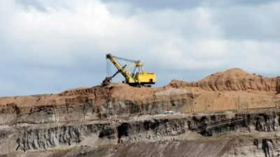
Mining shovels, excavators, draglines: Large surface mining machines trail cables of 6.6kV to 22kV rating across open-pit mining operations, with cable lengths of 500 meters to several kilometers. The cable is dragged through mud, across rock, and under extreme weather conditions.
Open-pit mining machines: Rotary blasthole drills, mobile crushers, and conveyor shift drives all trail cables across the pit floor. The cable must resist the abrasive and acidic conditions of pit environments.
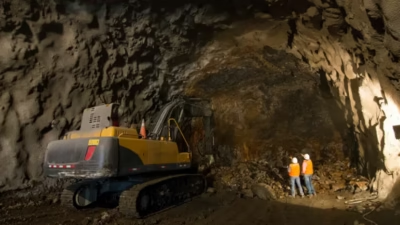
Tunnel boring machines (TBMs): TBM trailing cables operate in confined, wet underground environments where the cable is dragged through water, muck, and debris. The cable frequently passes under equipment tracks and is compressed against tunnel walls.
Mobile conveyor systems: Portable conveyor sections in mining and aggregate operations trail cables across the work area, repositioning as the operation advances.
Underground mining machines: Continuous miners, shuttle cars, load-haul-dump machines, and roof bolters trail cables through underground roadways. These cables are subject to the most severe abuse profile in all cable applications: ground drag, equipment crossover, rock fall, tight-radius bending around corners, and exposure to acidic mine water.
拖曳电缆的应力方向与卷筒电缆相反——攻击来自外部:地面磨蚀、设备碾压、岩石切割和冲击。工程应对策略是从外到内构建最厚、最坚韧的外部铠甲。4–6mm 厚的重型弹性体护套(CPE/PCP/EPR)是首要防线,而导体柔韧性和抗扭性成为次要考虑——因为电缆不在卷筒上缠绕,这些参数远不如护套抗磨蚀能力重要。
4. Head-to-Head Technical Comparison Table
| Feature | Reeling Cable | Trailing Cable |
|---|---|---|
| Motion Type | Wound / unwound on a drum | Dragged on the ground |
| Main Mechanical Stress | Tension, torsion, dynamic bending | Abrasion, cutting, crushing, impact |
| Bending Radius | Very small (6–8 × D) | Medium (8–12 × D) |
| Torsion Resistance | High (anti-torsion braid, cross-spiral lay) | Low (not required for ground drag) |
| Flex Life Cycles | Extremely high — millions of bending cycles | Moderate — designed for dragging, not drum cycling |
| Tensile Strength Member | Aramid (Kevlar) central core, standard | Typically absent; protection via sheath thickness |
| Conductor Stranding | Class 5 or Class 6 ultra-fine wire | Class 5 flexible stranding |
| Outer Sheath Material | PUR (polyurethane) — flexible, tear and UV resistant | CPE / EPR / PCP — very thick, crush and cut resistant |
| Sheath Thickness (typical) | 2.0 – 3.0 mm | 3.5 – 6.0 mm |
| Abrasion Resistance | Good (drum and sheave contact) | Excellent (continuous ground drag) |
| Crush Resistance | Moderate | Very high (equipment crossover rated) |
| Typical Voltage Range | 0.6/1 kV – 6.6/6.6 kV | 1.1/1.1 kV – 22/22 kV |
| Typical Use | Cranes, stacker-reclaimers, drilling rigs, reel-operated machinery | Mining shovels, excavators, draglines, continuous miners, TBMs |
| Primary Standards | IEC 60502, DIN VDE 0250, NEXANS BUFLEX-M | AS/NZS 1802, ICEA S-75-381 |
上表中绿色高亮单元格(.g)标识该电缆类型在对应参数上具有显著优势——但这并不意味着另一种类型是”劣质”的。每种电缆在其设计用途上都是最优解。卷筒电缆在柔韧性和抗扭方面卓越;拖曳电缆在护套厚度和抗压方面卓越。它们解决不同的问题。
5. Mechanical Stress Profiles: Why the Engineering Is Fundamentally Different
The most important thing to understand about the reeling-versus-trailing distinction is that these two cable types are engineered to solve opposite mechanical problems. They are not different grades of the same product; they are different products designed for different physics.
Reeling Cable Stress Profile: Tension + Bending + Torsion (Internal Fatigue)
A reeling cable’s enemies are internal. The repetitive combination of tensile loading, cyclic bending, and torsional deformation creates fatigue stresses within the cable structure—in the individual copper wire strands, in the insulation layers, in the sheath material, and at every interface between materials. Fatigue failure is progressive and largely invisible: individual wire strands break one at a time deep inside the conductor bundle, insulation develops micro-cracks at high-stress bending points, and sheath material slowly loses its elasticity through cyclic compression and tension. By the time external signs of failure appear (visible sheath cracking, increased electrical resistance, intermittent faults), the internal damage is already severe. Reeling cable design is therefore focused on fatigue resistance: every material must survive millions of stress cycles without progressive degradation. This requires fine-wire conductor stranding (more wires = more distributed stress per wire = longer fatigue life), flexible insulation compounds that resist cyclic compression, and sheath materials that maintain their elasticity over millions of bending cycles.
Trailing Cable Stress Profile: Abrasion + Crushing + Cutting + Impact (External Attack)
A trailing cable’s enemies are external. The cable’s outer surface is under continuous assault from the operating environment: abrasion from ground drag, crushing from equipment traffic, cutting from sharp rocks and metal edges, and impact from falling objects. These are predominantly surface-level attacks—they erode, puncture, and compress the cable from the outside inward. The engineering response is to build the maximum possible barrier between the environment and the electrical conductors. Trailing cable design is therefore focused on sheath toughness: the outer sheath must be thick enough to absorb wear without exposing the inner cable structure, hard enough to resist cutting and puncture, and resilient enough to recover from compression without permanent deformation (compression set). Unlike reeling cables, trailing cables do not need extreme flexibility or torsion resistance—they need raw mechanical protection.
Reeling Cable = Fatigue Resistance (internal, cyclic, progressive)Trailing Cable = Impact Resistance (external, acute, surface-inward)
This fundamental difference in stress direction—internal versus external, cyclic versus acute—is why the two cable types cannot be interchanged. A reeling cable’s thin, flexible sheath provides no defense against the external attacks that trailing cables face. A trailing cable’s thick, stiff sheath cannot survive the millions of bending cycles that reeling cables must endure.
6. Construction Philosophy: Built for Flexibility vs Built for Toughness
Reeling Cables: Engineered from the Inside Out for Flexibility
Conductors: Class 5 or Class 6 fine-wire stranding per IEC 60228. The conductor is composed of many thin individual wires (for a 50mm² conductor, typically 396 or more individual wires of 0.40mm diameter in Class 5, or even finer in Class 6) rather than the fewer, thicker wires used in fixed-installation cables. Each thin wire bends more easily than a thick wire, and the stranded bundle distributes bending stress across all wires, dramatically extending fatigue life.
Central strength member: An aramid fiber (Kevlar) rope runs through the geometric center of the cable, absorbing the tensile forces from the reeling drum. The aramid member has extremely high tensile strength-to-weight ratio and zero electrical conductivity, making it an ideal mechanical load-bearing element that does not interfere with the cable’s electrical function. Without this member, tensile forces would be borne entirely by the copper conductors, causing conductor stretching, work hardening, and eventual fracture.
Core lay-up: Cores are stranded with optimized short lay lengths (the distance over which a core completes one full rotation around the cable axis) that maximize flexibility while maintaining structural stability. Cross-spiral or counter-helical lay patterns balance the torsional forces that develop during drum winding, preventing the cable from developing a preferred twist direction that would cause Z-kinking.
Anti-torsion braid: A woven synthetic braid, embedded beneath the outer sheath, provides additional torsion resistance and distributes rotational forces uniformly around the cable circumference.
Sheath: Polyurethane (PUR) at 2.0–3.0mm thickness. PUR is chosen for its unique combination of high elasticity (returns to shape after bending), high tear resistance (resists propagation of surface nicks), oil resistance (maintains performance in contaminated environments), and UV stability (does not degrade in sunlight). PUR is more expensive than CPE or PCP but provides the flexibility essential for drum winding.
Trailing Cables: Engineered from the Outside In for Toughness
Sheath: Heavy-duty CPE (chlorinated polyethylene), PCP (polychloroprene), or EPR (ethylene propylene rubber) at 3.5–6.0mm thickness—often twice the thickness of a reeling cable sheath. The sheath is the primary engineering investment. It must resist grinding abrasion from continuous ground contact, survive being driven over by multi-tonne mining equipment, resist cutting from sharp rock and metal edges, and maintain integrity after impact from falling objects. The material is formulated for maximum toughness, which inherently makes it stiffer than PUR—a trade-off that is acceptable because the cable does not need to wind on a drum.
Semiconductive cradle: In medium-voltage trailing cables (per AS/NZS 1802), a semiconductive elastomeric layer surrounds each power core, providing uniform electrical field distribution and protecting the insulation from mechanical stress during ground-drag operation.
Conductors: Class 5 flexible stranding is standard, but the ultra-fine Class 6 stranding used in reeling cables is generally unnecessary. The conductor does not need to survive millions of tight-radius bending cycles; it needs to survive the general flexing associated with being dragged across rough ground. Class 5 provides adequate flexibility at lower cost.
No central strength member: Trailing cables are not subjected to the sustained, controlled tensile forces that reeling drums apply. Instead, they experience sporadic, irregular pulling forces as the machine advances. These forces are distributed across the cable’s cross-section by the sheath and internal cable structure, without requiring a dedicated aramid strength member.
两种设计哲学的核心差异:卷筒电缆从内向外为柔韧性而设计——极细丝导体、芳纶强度构件、短节距绞合、防扭编织、薄而弹性的 PUR 护套。拖曳电缆从外向内为坚韧性而设计——超厚重型弹性体护套、半导电支撑层、标准柔性导体、无需专用强度构件。两种电缆用完全不同的方式分配其”设计预算”。
7. Sheath Materials: PUR vs CPE/EPR and Why Each Exists
| Property | PUR (Polyurethane) — Reeling Cables | CPE (Chlorinated PE) — Trailing Cables | EPR (Ethylene Propylene) — Trailing Cables |
|---|---|---|---|
| Primary Strength | Flexibility + tear resistance | Crush + abrasion resistance | Chemical + heat resistance |
| Typical Thickness | 2.0 – 3.0 mm | 3.5 – 5.0 mm | 3.5 – 6.0 mm |
| Flex Fatigue Life | Excellent (millions of cycles) | Moderate (stiff material) | Moderate |
| Abrasion Resistance | Good | Excellent | Good |
| Crush Resistance | Moderate | Excellent | Very good |
| Oil Resistance | Excellent | Good | Moderate |
| UV Resistance | Excellent | Good (with additives) | Moderate |
| Acid Resistance | Moderate | Good (to pH 2.5) | Good |
| Flame Retardancy | Good (IEC 60332-1) | Excellent (inherent Cl content) | Good (with ATH filler) |
| Cost (relative) | Higher | Moderate | Moderate |
The sheath material selection is not interchangeable. PUR provides the elasticity and tear resistance that reeling cables need to survive millions of bending cycles on a drum, but it lacks the raw thickness and crush resistance that trailing cables require. CPE provides the armor-like toughness that trailing cables need to survive ground-drag abuse, but its stiffness would cause premature fatigue failure if wound on a reeling drum. Each material is the optimal choice for its intended application and a poor choice for the other application.
8. Bending Radius and Flex Life: The Numbers That Define Each Cable Type
| Parameter | Reeling Cable | Trailing Cable | Why It Matters |
|---|---|---|---|
| Min. Bending Radius (Fixed) | 6 × D | 8 × D | Tighter radius = smaller drum = more compact reel system |
| Min. Bending Radius (Dynamic) | 8 × D | 12 × D | Dynamic radius applies during actual operation (movement) |
| Flex Life (bending cycles) | 1,000,000+ cycles | ~50,000 – 100,000 cycles | Reeling cables must survive orders-of-magnitude more cycles |
| Torsion Tolerance | ±25° per meter (typical) | ±5° per meter (typical) | Drum winding introduces torsion that trailing service does not |
| Max. Reeling Speed | Up to 200 m/min (festoon); 60 m/min (drum) | N/A — not designed for drum use | Trailing cables are not operated on reeling drums |
The flex life difference is dramatic: reeling cables are designed for more than one million bending cycles at their rated bending radius, while trailing cables may tolerate fifty thousand to one hundred thousand cycles of moderate bending before fatigue degradation begins. This ten-to-twenty-fold difference in flex life reflects the fundamentally different construction—fine-wire conductors, flexible PUR sheath, short-lay core stranding, and aramid strength member versus standard conductors, thick CPE sheath, and conventional stranding. The flex life numbers are not negotiable; they are determined by the physics of metal fatigue and polymer fatigue in cyclic loading.
“D” refers to the cable’s overall outer diameter. For a cable with OD = 54mm, a minimum dynamic bending radius of 8×D equals 432mm (drum inner diameter of at least 864mm). Always verify bending radius against actual drum dimensions before procurement. If the drum is undersized, even a correctly specified reeling cable will fail prematurely.
9. What Happens When You Use the Wrong Cable Type
Using the wrong cable type is not merely suboptimal—it creates safety hazards, accelerates failure, and may violate mining safety regulations. Both scenarios described below are observed in the field with predictable consequences.
Scenario A: Trailing Cable Installed on a Reeling Drum
What happens: The thick, stiff CPE/EPR sheath resists bending around the drum surface, requiring significantly higher drum drive torque to spool the cable. The rigid sheath does not compress and conform to the drum surface the way PUR does—instead, it bridges between contact points, creating uneven winding that causes layer-to-layer interference and cable jamming. Inside the cable, the standard-grade conductors (designed for moderate flexing, not millions of drum cycles) experience concentrated bending stress at each contact point with the drum. Without an aramid strength member, the tensile forces from the drum drive are transmitted directly to the copper conductors, causing work hardening and eventual wire breakage. Without anti-torsion construction, the cable develops progressive Z-kinking as torsional stress accumulates over multiple winding layers.
Time to failure: Depending on operating intensity, visible degradation (sheath cracking, irregular winding, increased drive current) typically appears within two to eight weeks. Conductor failure (intermittent faults, increased resistance, eventual open circuit) follows within one to six months. The cable will never approach the multi-year service life that a properly specified reeling cable would deliver.
Scenario B: Reeling Cable Deployed as a Trailing Cable in a Mine
What happens: The thin PUR sheath (2.0–3.0mm), designed for drum-surface contact, is immediately exposed to the grinding abrasion of mine floor drag. PUR is tear-resistant but not thick enough to serve as a wear surface under continuous ground contact. The sheath wears through to the inner cable structure within days to weeks, depending on floor roughness and drag intensity. Once the sheath is breached, moisture, dust, and acidic mine water penetrate the cable interior. The fine-wire conductors, optimized for flexibility, are more vulnerable to damage from external impact than the sturdier conductors in trailing cables. The aramid central strength member—designed to absorb smooth, controlled drum tension—provides no protection against the irregular, multi-directional forces of ground-drag operation. Mining equipment running over the cable applies crushing forces that the thin PUR sheath cannot distribute, causing localized conductor deformation and insulation damage.
Time to failure: In aggressive mining environments (rocky floor, equipment crossover traffic, wet conditions), sheath breach can occur within days. Electrical failure follows within one to four weeks. The cable’s expected service life is reduced to less than five percent of what a properly specified trailing cable would provide.
两种错误使用场景都已在现场反复观察到。在卷筒上安装拖曳电缆:僵硬的护套导致缠绕不良、导体缺乏芳纶保护而承受拉伸破坏、无防扭结构导致 Z 扭结,通常 2–8 周出现可见退化。将卷筒电缆作为拖曳电缆在矿井使用:薄 PUR 护套在数天内被磨穿,水分和粉尘侵入电缆内部,极细丝导体易受外部冲击损伤,通常 1–4 周发生电气失效。
10. Application Decision Matrix: Which Cable for Which Machine
| Equipment / Application | Cable Motion | Correct Cable Type | Feichun Cable Product |
|---|---|---|---|
| STS / RTG Port Crane | Drum reeling or festoon | Reeling Cable | BUFLEX-M Series (PUR) |
| Tower Crane | Vertical drum reeling | Reeling Cable | BUFLEX-M Series (PUR) |
| Stacker-Reclaimer | Horizontal drum reeling | Reeling Cable | BUFLEX-M Series (PUR) |
| Drilling Rig (Reel-Mounted) | Drum reeling | Reeling Cable | BUFLEX-M 0.6/1kV or 3.6/6kV |
| Festoon / Drag Chain System | Festoon track or drag chain | Reeling Cable | BUFLEX-M Series (PUR) |
| Continuous Miner | Trailing on mine floor | Trailing Cable | Type 240 / Type 275 (AS/NZS 1802) |
| Shuttle Car | Trailing on mine floor | Trailing Cable | Type 240 / Type 275 (AS/NZS 1802) |
| Mining Shovel / Excavator | Trailing on pit floor | Trailing Cable | Type 240 (1.1kV – 11kV) |
| Dragline | Trailing on pit floor | Trailing Cable | Type 240 (6.6kV – 22kV) |
| Load-Haul-Dump (LHD) | Trailing in decline | Trailing Cable | Type 275 (3.3/3.3kV tropicalized) |
| Tunnel Boring Machine | Trailing in tunnel | Trailing Cable | Type 240 (3.3kV – 6.6kV) |
| Mobile Conveyor | Semi-trailing / repositioned | Trailing Cable | Type 240 (1.1kV – 3.3kV) |
| ASRS / Transfer Car | Drum reeling or festoon | Reeling Cable | BUFLEX-M Series (PUR) |
If there is any cable reel, drum, or festoon system involved in the cable’s operational movement, specify a reeling cable. If the cable lies on the ground and is pulled by the machine’s movement without passing through a drum or reel, specify a trailing cable. There are no hybrid applications—every installation falls clearly into one category or the other. If you are uncertain, contact Feichun Cable’s engineering team with your equipment model and operating conditions for a definitive recommendation.
11. Standards and Regulatory Framework
| Standard | Scope | Applies To |
|---|---|---|
| IEC 60502 | Power cables with extruded insulation, 1kV to 30kV | Reeling cables (general construction reference) |
| DIN VDE 0250 | German standard for power cables and flexible cords | Reeling cables (European market) |
| IEC 60228 | Conductor classification (Class 1 through Class 6) | Both reeling and trailing cables |
| IEC 60332-1 | Flame retardancy — single vertical cable test | Both reeling and trailing cables |
| AS/NZS 1802 | Electric cables — trailing cables for mining | Trailing cables (Australia, New Zealand, and influenced markets) |
| ICEA S-75-381 | Portable and power feeder cables for use in mines | Trailing cables (North America) |
| AS 1972 | Flexible cables for mining — reeling and trailing | Both types (Australian specific) |
| REACH / RoHS / CE | Environmental and substance compliance | Both types (international markets) |
Regulatory enforcement varies by jurisdiction. In Australian-influenced mining operations (including many Indonesian and Southeast Asian mines), AS/NZS 1802 compliance is verified by site electrical inspectors who check cable sheath markings, voltage ratings, and construction type against the site electrical management plan. Deploying a non-compliant cable type—even if technically adequate—can result in site shutdown orders. Always verify the applicable standard with the mine’s electrical engineer or site inspector before finalizing cable procurement.
12. Feichun Cable: Products for Both Applications
Anhui Feichun Special Cable Co., Ltd. manufactures both reeling cables and trailing cables as core product lines, covering the full range of voltage ratings, conductor sizes, and environmental specifications required by global mining and industrial markets. This dual capability means that a single supplier can provide correctly specified cables for every machine on a mine site—reel-operated drilling rigs, drum-equipped cranes, and ground-trailing mining equipment—with consistent quality standards, unified material traceability, and coordinated delivery logistics.
| Product Line | Cable Type | Voltage Range | Key Features |
|---|---|---|---|
| BUFLEX-M Series | Reeling Cable | 0.6/1kV – 6.6/6.6kV | PUR sheath, aramid strength member, Class 5 tinned Cu, anti-torsion braid, cross-spiral lay |
| Type 240 (AS/NZS 1802) | Trailing Cable | 1.1kV – 11kV | EPR insulation, composite Cu/polyester braid screen, heavy-duty elastomer sheath |
| Type 275 Tropicalized | Trailing Cable (Tropical) | 3.3/3.3kV | Tinned Cu, hydrolysis-resistant EPR, water-blocking fill, ultra-low-absorption CPE sheath |
| Custom Engineering | Both | Per specification | Application-specific designs for non-standard requirements, voltages, or environments |
Specification support: Feichun Cable’s engineering team provides cable selection assistance for projects where the correct cable type is uncertain. Provide the equipment model, operating voltage, cable management method (reel, festoon, or ground-trailing), and environmental conditions, and the engineering team will recommend the specific product and configuration.
Production and delivery: Standard production lead time is ten to fourteen weeks for both reeling and trailing cable lines. Shipping is available to all major global ports, with established logistics to Southeast Asia (Indonesia, Philippines, Vietnam), Australia, Africa, and South America mining markets.
Quality and traceability: Every production batch includes full material traceability documentation: conductor certificates, insulation compound batch records, sheath compound certificates, and factory test reports including voltage withstand, insulation resistance, and dimensional verification. This documentation supports mine site acceptance testing and satisfies international mining company due-diligence requirements.
飞纯电缆同时生产卷筒电缆和拖曳电缆两大核心产品线,覆盖全球矿业和工业市场所需的全部电压等级、导体规格和环境规格。单一供应商即可为矿场所有设备——卷筒式钻机、卷筒式起重机和地面拖曳式采矿设备——提供正确规格的电缆,并确保一致的质量标准、统一的材料可追溯性和协调的交付物流。