
What is JIS C CARCT Carrier Drum Cable & FFCT/FFCTB Heat Resistant Flexible Cable (200°C)? Complete Technical Analysis and VDE 0250-812 Comparison
Table of Contents
- 1. Introduction to CARCT and FFCT/FFCTB Cables
- 2. CARCT Carrier Drum Cable System
- 3. FFCT/FFCTB Heat Resistant Flexible Cables
- 4. Complete Technical Specifications
- 5. Ampacity Tables and Correction Factors
- 6. Comparison with VDE 0250-812
- 7. Installation Precautions by System Type
- 8. Safety Thresholds and Compliance
- 9. Operational Precautions and Maintenance
- 10. Common Problems and Troubleshooting
- 11. References and Citations
1. Introduction to CARCT and FFCT/FFCTB Cables
CARCT (Carrier Drum Cable Type) and FFCT/FFCTB (Heat Resistant Flexible Cable) represent two specialized classifications of industrial cables designed for demanding crane and material handling applications where conventional cables prove inadequate. These cables address distinct operational challenges: CARCT cables withstand the severe mechanical stresses encountered in carrier drum systems common to container handling equipment, while FFCT/FFCTB variants provide thermal resistance enabling continuous operation at conductor temperatures up to 200°C in high-temperature industrial environments.
Carrier drum systems represent a sophisticated cable management methodology employed extensively in container terminal operations, particularly for rubber-tired gantry (RTG) cranes and rail-mounted gantry (RMG) cranes where cables must accommodate horizontal travel distances spanning dozens of meters while maintaining electrical integrity under continuous cyclic loading. The carrier drum methodology suspends cables from wire rope supports attached to mobile carrier platforms that traverse alongside crane movement, distributing mechanical loads across multiple suspension points rather than concentrating stress at cable terminations.
Reeling cables for mobile machinery in port terminals must endure dynamic motion, harsh environmental conditions, and heavy mechanical stress while ensuring reliable operations, with specialized engineering required to accommodate the extreme demands of container handling equipment operating 24/7 in maritime environments. The fundamental distinction between carrier drum cables and conventional reeling or festoon variants lies in their construction philosophy emphasizing crush resistance, smooth surface finish facilitating cable sliding through support mechanisms, and optimized flexibility enabling compact coiling within restricted drum diameters.
Container Terminal Cable Management Systems:
Modern container terminals employ diverse cable management technologies adapted to specific equipment configurations and operational requirements. Carrier drum systems excel in applications requiring horizontal traverse motion across extended distances (typically 20-100 meters) where festoon systems prove impractical due to space constraints or excessive trolley infrastructure costs. The system comprises a cable drum mounted on the moving equipment (crane or carrier), wire rope suspensions maintaining cable elevation throughout travel range, and cable clamps securing both fixed and moving terminations to prevent core displacement during operation.
FFCT and FFCTB heat resistant flexible cables address operational requirements in environments where ambient temperatures, radiant heat sources, or electrical loading conditions generate conductor temperatures exceeding the 80-90°C capabilities of standard EPR-insulated cables. Applications include steel mill cranes operating in proximity to molten metal, foundry material handling equipment exposed to radiant heat from casting operations, high-temperature furnace charging systems, and specialized industrial processes requiring cable operation in elevated temperature zones. The conductor temperature rating of 200°C continuous operation represents a 150% increase over standard industrial cable capabilities, necessitating specialized insulation materials, heat-resistant sheath compounds, and thermal barrier technologies.
2. CARCT Carrier Drum Cable System
2.1 System Architecture and Operational Principles
The carrier drum system represents an elegant engineering solution balancing cable protection, system reliability, and installation economy for horizontal crane motions. Unlike festoon systems requiring continuous track infrastructure or drum reeling systems concentrating mechanical stress during winding operations, carrier drum configurations distribute cable weight across multiple suspension points while maintaining sufficient slack to accommodate equipment motion without imposing tensile loading on electrical conductors.
The system operational sequence commences with cable installation whereby the cable extends from a fixed power supply point (typically at one end of crane travel range) through a series of suspension points to the mobile equipment. Cable clamps at both fixed and mobile terminations prevent internal core displacement that would otherwise result from differential friction between cores during system motion. Wire rope supports attached to the carrier drum maintain cable elevation, with the wire rope length specified at 0.9× cable length ensuring the wire rope bears tensile loading while the cable maintains a gentle catenary curve throughout travel range.
CARCT Cable Design Features:
- Superior Squeeze Resistance: Enhanced sheath compounds and core fillers prevent deformation when cables coil on drums or pass through guide systems under compression loading
- Tough Wear-Resistant Sheath: Specialized chloroprene or polyurethane formulations withstand abrasion from contact with carrier drum surfaces and guide rollers
- Smooth Surface Finish: Precision extrusion processes achieve surface roughness values below 2.0 μm Ra, minimizing friction during cable sliding through support mechanisms
- Optimized Flexibility: Class 5 or Class 6 conductor stranding combined with engineered core lay geometries enable 6D minimum bending radius
- Balanced Construction: Symmetrical core arrangements and filler materials prevent preferential bending directions that could cause twist accumulation during cyclic operations
2.2 Application Domains and Equipment Types
CARCT cables serve primarily in container terminal operations where horizontal crane traverse motions dominate operational profiles. Rubber-tired gantry cranes represent the most common application, with these highly mobile machines requiring electrical power transmission across travel ranges typically spanning 30-60 meters as they navigate container yard blocks. The carrier drum methodology proves particularly advantageous for RTG applications due to the absence of fixed infrastructure (no festoon tracks required), reduced maintenance requirements compared to drum reeling systems prone to wire rope wear, and enhanced cable service life resulting from distributed mechanical loading rather than concentrated winding stresses.
Rail-mounted gantry cranes similarly benefit from carrier drum cable management, particularly in automated or semi-automated configurations where reliability assumes paramount importance due to minimal operator intervention opportunities. Automated stacking cranes (ASC) in high-density container storage facilities employ carrier drum systems for both main power transmission and auxiliary control/data circuits, with the system’s inherent reliability reducing unplanned maintenance interventions that would otherwise disrupt automated operations and compromise terminal throughput objectives.
2.3 CARCT Technical Ratings and Performance Parameters
| Parameter | Value | Standard/Test Method |
|---|---|---|
| Rated Voltage | 600V AC | JIS C 3327 |
| Test Voltage | 3000V AC / 1 minute | Dielectric withstand test |
| Max. Operating Temperature | 80°C (conductor) | Continuous rating |
| Short Circuit Temperature | 250°C (5 seconds max) | Emergency overtemperature limit |
| Minimum Bending Radius | 6 × cable diameter | Dynamic flexing applications |
| Recommended Drum Diameter | ≥10 × cable diameter | Low-voltage cables |
| Permissible Lateral Pressure (with reinforcement) | ≤4.9 kN/m (500 kgf/m) | Crush resistance specification |
3. FFCT/FFCTB Heat Resistant Flexible Cables
3.1 Thermal Performance and Material Engineering
FFCT and FFCTB cables achieve their exceptional 200°C conductor temperature rating through implementation of advanced insulation materials, thermal barrier technologies, and specialized construction methodologies absent from conventional industrial cables. The primary insulation system employs silicone rubber compounds exhibiting superior thermal stability compared to organic polymer alternatives (EPR, XLPE, PVC), with silicone maintaining dielectric properties and mechanical integrity throughout the -60°C to +200°C temperature spectrum. Silicone rubber chemistry based on polydimethylsiloxane (PDMS) polymer chains with cross-linking provides inherent thermal oxidation resistance, maintaining flexibility and electrical properties even after extended exposure to elevated temperatures that would cause embrittlement and failure in organic polymer systems.
The FFCT variant incorporates a glass tape wrapping surrounding individual insulated cores, providing mechanical protection and additional thermal insulation reducing heat transfer between cores under high-current loading conditions. Glass fiber tape, typically comprising E-glass or S-glass filaments in non-woven or woven configurations, exhibits exceptional thermal stability (melting point >1000°C) and provides mechanical reinforcement preventing insulation deformation under thermal cycling. The glass tape layer additionally serves as a migration barrier preventing silicone oils from transferring between cores or bleeding through to the outer sheath, a phenomenon that could compromise cable aesthetics or cause contamination in clean room applications.
FFCTB Enhanced Construction Features:
The FFCTB variant builds upon FFCT capabilities through addition of a stainless steel braided shield positioned between the glass tape and outer sheath layers. This metallic braid serves multiple critical functions including electromagnetic interference (EMI) shielding essential in high-electrical-noise environments common to industrial facilities, mechanical protection against impact damage and abrasion exceeding that provided by elastomeric sheaths alone, and thermal dissipation enabling enhanced current-carrying capacity compared to FFCT equivalents. The stainless steel construction (typically 304 or 316 grade) ensures corrosion resistance in humid or chemically aggressive environments where carbon steel braids would deteriorate rapidly, maintaining protection throughout extended service lives exceeding 10-15 years in demanding industrial applications.
3.2 Application Environments and Industry Sectors
FFCT/FFCTB cables find primary application in steel production facilities where cranes, charging machines, and material handling equipment operate in proximity to radiant heat sources including molten metal, furnace openings, and hot rolled products. Ladle cranes transporting molten steel from furnaces to casting operations experience conductor temperatures approaching or exceeding 100°C from radiant heat exposure alone, requiring heat-resistant cable constructions to prevent premature insulation failure. Billet handling cranes in continuous casting operations similarly encounter elevated temperature zones where conventional cables would experience accelerated aging and reduced service life.
Foundry operations present comparable challenges, with overhead cranes, jib cranes, and mobile equipment serving casting areas subjected to intermittent but severe thermal exposures. Glass manufacturing facilities employ FFCT/FFCTB cables for machinery operating near furnaces and forming operations where ambient temperatures routinely exceed 60-80°C. Ceramic production, including brick and tile manufacturing, represents another application sector where heat-resistant cables prove essential for kiln charging equipment and material handling systems serving high-temperature processing zones.
3.3 FFCT/FFCTB Technical Specifications
| Parameter | FFCT Value | FFCTB Value | Notes |
|---|---|---|---|
| Rated Voltage | 600V AC | 600V AC | Phase-to-ground rating |
| Test Voltage | 3000V AC / 1 min | 3000V AC / 1 min | Dielectric withstand test |
| Max. Operating Temperature | 200°C | 200°C | Conductor continuous rating |
| Insulation Material | Silicone Rubber | Silicone Rubber | PDMS-based compound |
| Thermal Barrier | Glass Tape Wrap | Glass Tape + Stainless Braid | Enhanced protection in FFCTB |
| Sheath Material | Silicone Rubber | Silicone Rubber | Heat resistant compound |
| Typical Weight Increase vs. FFCT | – | +20-30% | Due to stainless braid addition |
| Ampacity Derating (vs. FFCT) | – | -10 to -15% | Due to thermal resistance of braid |
4. Complete Technical Specifications
4.1 CARCT Carrier Drum Cable Specifications
| Type | Cores × Size (mm²) | Conductor Ø (mm) | Nominal OD (mm) | Max OD (mm) | Weight (kg/km) |
|---|---|---|---|---|---|
| CARCT | 3×8 | 3.7 | 17 | 17.9 | 475 |
| CARCT | 3×14 | 4.9 | 20 | 21.0 | 730 |
| CARCT | 3×22 | 7.0 | 26 | 27.3 | 1,180 |
| CARCT | 3×30 | 8.1 | 28 | 29.4 | 1,470 |
| CARCT | 3×38 | 9.1 | 31 | 32.6 | 1,790 |
| CARCT | 3×60 | 11.6 | 38 | 39.9 | 2,790 |
| CARCT | 4×38 | 9.1 | 34 | 35.7 | 2,280 |
| CARCT | 6×3.5 | 2.5 | 17 | 17.9 | 465 |
| CARCT | 6×8 | 3.7 | 22 | 23.1 | 890 |
| CARCT | 6×14 | 4.9 | 27 | 28.4 | 1,390 |
| CARCT | 6×22 | 7.0 | 34 | 35.7 | 2,220 |
| CARCT | 10×3.5 | 2.5 | 23 | 24.2 | 790 |
| CARCT | 12×3.5 | 2.5 | 24 | 25.2 | 815 |
| CARCT | 16×3.5 | 2.5 | 26 | 27.3 | 1,080 |
| CARCT | 20×3.5 | 2.5 | 29 | 30.5 | 1,330 |
| CARCT | 24×3.5 | 2.5 | 32 | 33.6 | 1,630 |
| CARCT | 30×3.5 | 2.5 | 36 | 37.8 | 2,080 |
4.2 FFCT Heat Resistant Cable Specifications
| Type | Cores × Size (mm²) | Cond. Ø (mm) | Nominal OD (mm) | Max OD (mm) | Weight (kg/km) | Ampacity* (A) |
|---|---|---|---|---|---|---|
| FFCT | 1×100 | 15.2 | 22 | 23.1 | 1,230 | 570 |
| FFCT | 1×200 | 21.2 | 29 | 30.5 | 2,270 | 880 |
| FFCT | 1×325 | 27.0 | 36 | 37.8 | 3,660 | 1,180 |
| FFCT | 2×2 | 1.8 | 10 | 10.5 | 140 | 38 |
| FFCT | 2×3.5 | 2.5 | 12 | 12.6 | 205 | 55 |
| FFCT | 3×2 | 1.8 | 10 | 10.5 | 165 | 32 |
| FFCT | 3×3.5 | 2.5 | 12 | 12.6 | 245 | 47 |
| FFCT | 4×2 | 1.8 | 11 | 11.6 | 200 | 29 |
| FFCT | 4×3.5 | 2.5 | 13 | 13.7 | 300 | 43 |
| FFCT | 6×2 | 1.8 | 13 | 13.7 | 290 | 25 |
| FFCT | 10×2 | 1.8 | 17 | 17.9 | 480 | 20 |
| FFCT | 20×2 | 1.8 | 22 | 23.1 | 825 | 16 |
| FFCT | 30×2 | 1.8 | 25 | 26.3 | 1,190 | 13 |
* Ampacities based on 30°C ambient, 200°C conductor temperature, single cable in air. Apply correction factors for different conditions.
4.3 FFCTB Enhanced Shield Braid Specifications
| Type | Cores × Size (mm²) | Cond. Ø (mm) | Nominal OD (mm) | Max OD (mm) | Weight (kg/km) | Ampacity* (A) |
|---|---|---|---|---|---|---|
| FFCTB | 1×100 | 15.2 | 27 | 28.3 | 1,560 | 510 |
| FFCTB | 1×200 | 21.2 | 34 | 35.7 | 2,710 | 760 |
| FFCTB | 1×325 | 27.0 | 40 | 42.0 | 4,180 | 1,000 |
| FFCTB | 2×2 | 1.8 | 15 | 15.7 | 310 | 37 |
| FFCTB | 2×3.5 | 2.5 | 16 | 16.8 | 395 | 53 |
| FFCTB | 3×2 | 1.8 | 15 | 15.7 | 340 | 31 |
| FFCTB | 3×3.5 | 2.5 | 17 | 17.8 | 445 | 47 |
| FFCTB | 4×2 | 1.8 | 16 | 16.8 | 390 | 28 |
| FFCTB | 4×3.5 | 2.5 | 18 | 18.9 | 515 | 44 |
| FFCTB | 6×2 | 1.8 | 18 | 18.9 | 505 | 25 |
| FFCTB | 10×2 | 1.8 | 22 | 23.1 | 760 | 20 |
| FFCTB | 20×2 | 1.8 | 27 | 28.3 | 1,190 | 15 |
| FFCTB | 30×2 | 1.8 | 31 | 32.5 | 1,610 | 13 |
* Ampacities based on 30°C ambient, 200°C conductor temperature, single cable in air. Note reduced ampacity vs. FFCT due to stainless braid thermal resistance.
5. Ampacity Tables and Correction Factors
5.1 Standard Ampacity Tables
Ampacity calculations for industrial cables must account for multiple variables including conductor size, insulation type, installation method, ambient temperature, and loading factors. The tables below provide baseline ampacity values for standard cable configurations, with subsequent correction factors enabling adjustment for specific installation conditions.
JIS Size Standard Structure (600V Round Flexible Cable)
| Cross-Section (mm²) | Single-Core (A) | 2-Cores (A) | 3-Cores (A) | 4-Cores (A) | 5-Cores (A) |
|---|---|---|---|---|---|
| 0.75 | 19 | 15.5 | 13.5 | 12.5 | 11.5 |
| 1.25 | 25 | 21 | 18 | 16.5 | 15.5 |
| 2 | 32 | 27 | 23 | 21 | 19 |
| 3.5 | 47 | 39 | 33 | 30 | 28 |
| 5.5 | 62 | 51 | 44 | 40 | 37 |
| 8 | 77 | 63 | 54 | 49 | 46 |
| 14 | 109 | 89 | 76 | 69 | 64 |
| 22 | 149 | 121 | 103 | 93 | 86 |
| 30 | 180 | 145 | 123 | 111 | 103 |
| 38 | 209 | 166 | 142 | 128 | 118 |
| 50 | 245 | 194 | 165 | 149 | 140 |
| 60 | 281 | 221 | 188 | 171 | 161 |
| 80 | 340 | 268 | 231 | 211 | 198 |
| 100 | 393 | 311 | 269 | 244 | 229 |
Based on 30°C ambient temperature, 80°C conductor max rating, single cable in air. Source: JIS Standard structures.
IEC Size Standard Structure (0.6/1kV Round Flexible Cable)
| Cross-Section (mm²) | 3-Cores (A) | 4-Cores (A) | 5-Cores (A) |
|---|---|---|---|
| 1.5 | 21 | 19 | 18 |
| 2.5 | 29 | 26 | 24 |
| 4 | 38 | 35 | 33 |
| 6 | 49 | 44 | 41 |
| 10 | 69 | 62 | 58 |
| 16 | 92 | 83 | 77 |
| 25 | 120 | 109 | 101 |
| 35 | 148 | 133 | – |
| 50 | 183 | 165 | – |
| 70 | 227 | 202 | – |
| 95 | 265 | 239 | – |
Based on 30°C ambient temperature, 90°C conductor max rating, single cable in air. Source: IEC structures per 0.6/1kV FTNCT standard.
5.2 Correction Factors for Various Conditions
① Correction Factors for Multi-Core Cables
| No. of Cores | 4 | 5 | 6 | 7 | 8 | 9 | 10 | 11 | 12 |
|---|---|---|---|---|---|---|---|---|---|
| Correction Factor | 0.65 | 0.59 | 0.55 | 0.51 | 0.49 | 0.46 | 0.44 | 0.43 | 0.42 |
| No. of Cores | 13 | 14 | 15 | 16 | 17 | 18 | 19 | 20 | 21 |
|---|---|---|---|---|---|---|---|---|---|
| Correction Factor | 0.41 | 0.40 | 0.39 | 0.38 | 0.37 | 0.36 | 0.36 | 0.35 | 0.34 |
| No. of Cores | 22 | 23 | 24 | 25 | 26 | 27 | 28 | 29 | 30 |
|---|---|---|---|---|---|---|---|---|---|
| Correction Factor | 0.33 | 0.33 | 0.32 | 0.32 | 0.31 | 0.30 | 0.30 | 0.29 | 0.29 |
② Correction Factors for Different Ambient Temperatures
Correction Factor = (Rated Temperature – Actual Ambient) / (Rated Temperature – Given Ambient for Given Ampacity)
| Ambient Temp (°C) | 20 | 25 | 30 | 35 | 40 | 45 | 50 | 55 | 60 | 65 | 70 |
|---|---|---|---|---|---|---|---|---|---|---|---|
| JIS Size Correction | 1.08 | 1.04 | 1.00 | 0.96 | 0.91 | 0.87 | 0.82 | 0.76 | 0.71 | 0.65 | 0.58 |
| IEC Size Correction | 1.10 | 1.05 | 1.00 | 0.95 | 0.89 | 0.84 | 0.77 | 0.71 | 0.63 | 0.55 | 0.45 |
③ Correction Factors for Reel Systems
| System Type | Correction Factor | Remarks |
|---|---|---|
| Single Layer (1 wrap) | 1.00 | Reference condition |
| Double Layer (2 wraps) | 0.85 | Reduced heat dissipation |
| Triple Layer (3 wraps) | 0.65 | Significant thermal buildup |
| Four Layers (4 wraps) | 0.45 | Severely restricted cooling |
| Five Layers (5 wraps) | 0.35 | Not recommended for continuous duty |
| Eight Layers (8 wraps) | 0.31 | Emergency/intermittent use only |
| Ten Layers (10+ wraps) | 0.28 | High risk of thermal failure |
④ Correction Factors for Multiple Installation in Air
| Number of Cables | Correction Factor (S/d ≥ 2) | Remarks |
|---|---|---|
| 1 | 1.00 | Single cable reference |
| 2 | 0.85 | Minimum spacing required: 2× cable diameter |
| 3 | 0.65 | Triangular or linear arrangement |
| 4 | 0.45 | Square or linear arrangement |
| 5 | 0.35 | Multiple grouping configurations |
S = Distance between cable centers; d = Cable diameter. For S/d < 2, additional derating required. Source: JCS 0168-1 Japanese Cable Maker's Association Standard.
5.3 Short-Circuit Temperature Calculation
Approximate short-circuit current capacity can be calculated using the following formula for determining maximum permissible short-circuit duration before conductor temperature reaches the 250°C emergency limit:
I²t = K × A²
Where:
I = Short-circuit current (Amperes)
t = Duration (seconds)
K = Material constant (copper: 143 A²s/mm⁴ for 80°C to 250°C)
A = Conductor cross-sectional area (mm²)
For example, a 3.5mm² copper conductor rated at 80°C normal operation can withstand approximately 14.7 kA for 0.1 seconds, or 4.7 kA for 1.0 second before reaching the 250°C short-circuit temperature limit. These calculations prove critical for protective device coordination ensuring circuit breakers or fuses operate before cables sustain thermal damage during fault conditions.
6. Comparison with VDE 0250-812 (German Standard)
VDE 0250-812, the German standard for heavy-duty flexible cables (NSSHÖU designation), represents an alternative engineering approach to crane cable specifications emphasizing comprehensive European harmonization and extensive field-proven performance spanning decades of industrial deployment. While both JIS C standards (governing CARCT and FFCT/FFCTB cables) and VDE 0250-812 address material handling cable requirements, significant philosophical and technical differences emerge from comparative analysis.
| Parameter | JIS C CARCT | JIS C FFCT/FFCTB | VDE 0250-812 NSSHÖU |
|---|---|---|---|
| Geographic Origin | Japan | Japan | Germany (Europe) |
| Voltage Rating | 600V | 600V | 450/750V (U₀/U) |
| Test Voltage | 3000V / 1 min | 3000V / 1 min | 3000V / 15 min |
| Max Operating Temp | 80°C | 200°C | 80°C |
| Primary Application | Carrier drum systems | High-temperature environments | General reeling applications |
| Insulation Material | EPR | Silicone Rubber | EPR per VDE 0207-21 |
| Sheath Material | Chloroprene (CR) | Silicone Rubber | Polychloroprene per VDE 0207-20 |
| Special Features | Squeeze resistance, smooth surface | Glass tape, optional SS braid | Heavy-duty universal construction |
| Minimum Bending Radius | 6D (dynamic) | 6D (recommended) | 5-8D application dependent |
| Ambient Temp Range | -25°C to +80°C | -60°C to +200°C | -40°C to +80°C |
The Japanese standards reflect design philosophies emphasizing application-specific optimization (carrier drum focus for CARCT, thermal performance for FFCT/FFCTB) versus the European approach favoring broad applicability across diverse installation types. CARCT cables incorporate smooth surface finishes and enhanced squeeze resistance tailored specifically for carrier drum operational dynamics, features not explicitly specified in VDE 0250-812 which addresses general reeling applications encompassing both horizontal and vertical configurations. FFCT/FFCTB cables represent a thermal performance class entirely absent from VDE 0250-812, with the 200°C rating addressing high-temperature industrial sectors where European practices typically employ entirely different cable technologies (mineral-insulated cables, ceramic fiber-wrapped conductors).
The voltage rating disparity (600V Japanese versus 450/750V European) reflects different industrial distribution practices, with both providing adequate margins for typical 380-480V three-phase crane power systems. The test voltage duration difference (1 minute versus 15 minutes) represents contrasting verification philosophies: Japanese standards emphasize practical manufacturing test feasibility and cost, while European standards impose more rigorous qualification demonstrating sustained insulation integrity under extended overvoltage conditions.
7. Installation Precautions by System Type
7.1 Carrier Drum System Installation Requirements
Critical Carrier Drum Installation Precautions:
- Bending Radius Compliance: Permissible bending radius (R) shall be 10D minimum for round low-voltage cables, where D represents cable diameter. For medium-voltage variants, increase to 12D minimum.
- Cable Twist Removal: Remove all torsion from cable before installation. Cables installed with residual twist will develop stress concentration points leading to premature failure. Inspect cable along entire length ensuring no visible spiral patterns indicate retained torsion.
- Wire Rope Tension Management: Carrier drums must be transferred using wire ropes as tension members. Ensure no tension applies directly to cables – maintain sufficient slack at all positions throughout travel range. Wire rope length specification: 0.9× cable length ensures proper load distribution.
- Terminal Clamping Methodology: Fix supply and receiving ends securely using split clamps with minimum 100mm contact length. Targeted cable deformation ratio: approximately 15% for low-voltage cables, 5% for high-voltage variants. Insufficient clamping causes corkscrewing or kinking potentially resulting in short-circuit conditions.
- Lateral Pressure Limitations: For cables with sheath reinforcement, maximum permissible lateral pressure: 4.9 kN/m (500 kgf/m). Exceeding this threshold causes permanent cable deformation compromising electrical insulation integrity.
- Straight Section Requirements: The length of straight-line portion from fixed end to radius curve end must be secured to longest possible extent. Target length: 20× cable diameter minimum. This reduces stress concentration at transition points.
7.2 Reel System (Traveling) Installation Specifications
- Permissible Bending Radius: Round cable bending radius R ≥ 6D for low-voltage applications (D = cable diameter). This specification applies during dynamic winding/unwinding operations.
- Tension and Lateral Pressure Control: Constant and instantaneous tension applied to cable must remain below permissible levels specified in cable documentation. Lateral pressure with reinforced sheath construction: maximum 4.9 kN/m as previously noted.
- Twist Prevention During Winding: Never wind cables in twisted state. When winding round cables on cylindrical reels, apply traverser mechanism for array winding operation. Random winding induces cable twisting leading to conductor damage and insulation stress.
- Cable Guide Roller Configuration: For applications employing cable guide rollers, verify minimum permissible bending radius compliance at all roller contact points. Rollers must rotate freely without binding or excessive friction.
- Straight Line Extension from Storage Reel: Ensure cable extends only in straight line from storage reel during installation. Non-linear unwinding causes twisting potentially damaging cable internal structure before operational service commences.
- Relative Position Maintenance: During operation, reel system components (reel, guide roll, side roll, pit) must maintain relative positions without deviation. For flat cables specifically, no lateral pressure shall apply in direction of shorter dimension.
- Terminal Clamping at Fixed Ends: Clamp fixed ends after winding more than one turn around anchor drum, or clamp by two points inserting wire saddle between clamps while snaking the cable. Initial grip force requirement: 2× maximum cable tension. Insufficient clamping causes corkscrewing or kinking.
7.3 Festoon and Chain System Precautions
Festoon System Specific Requirements:
- Bending Radius for Festoon Applications: Minimum R ≥ 6D for low-voltage round cables. Attach bar to each hanger securing minimum bending radius when gathering system components.
- Cable Hanger Connection: Cable hangers (first hanger connected to structure) shall connect with wire rope or chain as tension member. Do not apply tension directly to cables. Wire rope or chain length: less than 0.9× cable length.
- Hanger Fixation: Cable hanger must be fixed preventing rotation unless system design specifically requires rotatable hangers (spiral suspension applications). For rotatable configurations, torsional angle maximum 70°/meter (recommended: 35°/meter maximum).
- Twist Management: Do not unfold system while cables remain twisted. For multiple installations, clamp all conductors securely ensuring cable becomes flat-shaped configuration.
- Fixed End Installation: Install fixed cable ends by winding around drum or hanger with permissible bending radii or greater, preventing concentrative stress by bending or tension at fixed ends when cable moves.
Chain System Specific Requirements:
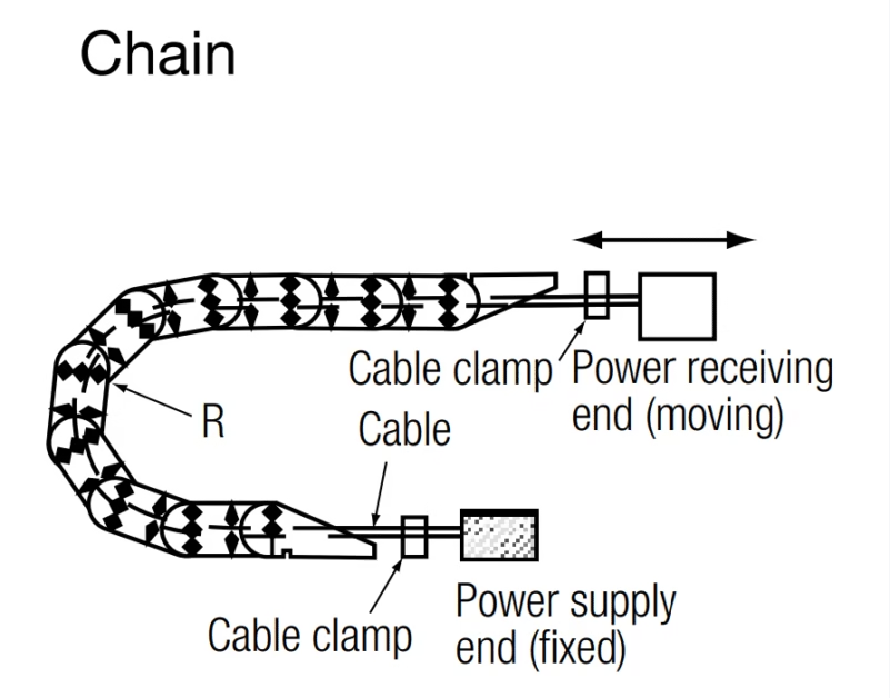
- Support System Configuration: Recommended: caterpillar system supporting cables so centers locate at track centers. Hole diameter for supports must enable cables to move loosely within considerable clearance, preventing unreasonable bending or force when tracks bend.
- Single Cable Per Support: Route only one cable into each support hole. Multiple cables in single hole causes interference and uneven loading potentially damaging cable sheaths.
- Box-Type Guide Implementation: When using box-type guides, ensure cables do not overlap inside box. Use dividers if necessary preventing interference between cables and maintaining proper spacing throughout travel range.
7.4 Torsion System Applications
Torsion System Critical Parameters:
- Bending Radius Minimum: 6× cable diameter minimum for low-voltage cables under torsional loading conditions.
- Cable Length Optimization: Secure cable length to longest possible extent, installing so torsional angle per unit length becomes as small as possible. Maximum torsional angle: 70°/meter. Recommended value: ±35°/meter maximum.
- Multiple Cable Interference Prevention: For hanging multiple cables, prevent any interference between adjacent cables. Do not bundle and fix cables with banding ties or similar fasteners as this concentrates torsional stress.
- Fixed End Stress Reduction: To prevent concentrative torsional stress at fixed ends, secure longer length for straight-line cable portions or create sufficient bending radii at fixed ends during installation.
- Cable Length Variation Accommodation: Cable length varies when twisted – provide sufficient slack accommodating length changes during torsional motion cycles.
- Specialized Applications: Consult manufacturer when using cables under severe torsional conditions, or for single-core or shielded type cables where torsional effects may compromise shield integrity or induce electromagnetic interference issues.
7.5 Spreader (Basket) System Installation
- Coiling Considerations: Torsion may occur when pulling up cable in coiled state. After pulling up, install cable in direction where twisting becomes tight (S-lay laid cables shall be collected clockwise direction).
- Coiling Diameter Specification: Coiling diameter must be secured to largest possible extent – minimum 20× cable diameter. Smaller coiling diameters induce excessive stress concentration during basket collection operations.
- Surface Lubrication: Apply grease on cable surface before installation facilitating smooth cable motion during basket collection and deployment cycles while reducing friction-induced wear.
- Application-Specific Consultation: Contact manufacturer for cable selection since requirements depend on basket configuration, lifting height, and lifting speed parameters specific to equipment installation.
7.6 Moving Pulley System Requirements
- Reel Diameter Specification: Reel diameter (D) shall be 20D minimum where D represents cable diameter. Smaller reel diameters cause excessive bending stress accelerating fatigue failure.
- Reel Rotation Quality: Ensure reels rotate smoothly without binding or excessive friction. Periodic lubrication of reel bearings maintains smooth rotation throughout service life.
- Weight and Load Minimization: Moving reel weight and load shall be minimized preventing cable slack and reducing tension applied to cable. Excessive reel mass requires higher cable tensions potentially exceeding design limits.
- Terminal Clamping Methodology: For fixed ends, clamp by two points inserting wire saddle between clamps and snaking the cable. Initial grip force: 2× maximum cable tension minimum.
- Application Limitations: As cable experiences simultaneous tension, bending, and lateral pressure in moving pulley systems, this configuration proves unsuitable for high-frequency applications where cumulative fatigue effects rapidly degrade cable integrity.
7.7 Lift System (Elevator) Precautions
- Suspension Distance Specification: Distance between adjacent suspensions shall be 12× cable diameter minimum for low-voltage cables. This spacing prevents excessive sag while avoiding over-tensioning cable conductors.
- Multiple Cable Interference Management: When hanging multiple cables, ensure no interference between adjacent cables occurs during elevator motion. Consider staggering cable support heights installing cables on different levels when multiple cables occupy same vertical space.
- Straight Section Length: Length of straight-line portion from fixed end to radius curve end must be secured to longest possible extent – target length: 20× cable diameter minimum.
- Counterweight Usage: Using cable attached with counterweight causes lateral pressure and corkscrewing potentially resulting in short-circuit conditions. Consult manufacturer for appropriate cable selection for counterweight applications.
- Severe Condition Consultation: Consult manufacturer when using cables under severe conditions including extended stroke length, high frequency operation, or elevated speed parameters exceeding standard specifications.
- Elevator-Specific Cables: For normal elevator applications, use specified lift control cables designed specifically for elevator duty cycles and safety requirements rather than general-purpose flexible cables.
8. Safety Thresholds and Compliance
8.1 Electrical Safety Requirements
⚠️ CRITICAL ELECTRICAL SAFETY WARNINGS:
- Risk of Electric Shock or Fire:
- Never perform connecting and wiring operations with power switched ON. Verify electrical isolation using approved voltage detection equipment before commencing work.
- Do not disassemble or alter products. Unauthorized modifications void warranties and compromise safety systems potentially causing catastrophic failure.
- Ensure grounding of shielding layers where present. Note: Single-ended grounding induces voltage at ungrounded end; double-ended grounding may cause temperature increase in shielding layer requiring careful evaluation.
- Risk of Burn Injury, Burnout, or Fire:
- Never apply voltage or current exceeding rated levels. Overloading causes conductor overheating potentially igniting insulation materials and adjacent combustibles.
- Do not use cables exceeding rated temperature in consideration of operating environment. FFCT/FFCTB cables rated 200°C; standard CARCT rated 80°C – verify application-appropriate specifications before installation.
8.2 Installation and Processing Prohibitions
Prohibited Matters at Wire/Cable Processing:
- High-Voltage Terminal Joint Installation: When installing terminal joint of high-voltage cable, remove outer semiconductive layer thoroughly without any residue. Residual semiconductive material causes insulation failure through electrical tracking establishing conductive paths between conductor and ground.
- Torsion Elimination: Do not install wire or cable with retained torsion. Torsion damages products through stress concentration points causing conductor breakage and insulation cracking during operational flexing cycles.
- Application-Appropriate Usage: Do not use wire or cable for purposes other than those specified for each product. Inappropriate applications subject cables to stresses exceeding design parameters causing premature failure.
- Moisture Ingress Prevention: Ensure no water enters conductor during termination operations. Moisture contamination causes corrosion and creates low-resistance paths compromising electrical insulation over time.
8.3 Handling Precautions
- Tension and Bending Radius Compliance: Ensure tension or bending radius does not exceed permissible levels specified in product documentation. Violations break or damage conductors shortening product life through accumulated fatigue effects.
- Terminal Clamping Under Dynamic Loading: When cable subjects to tension or vibration, clamp terminals securely preventing cores from wrongly positioning. Core displacement damages products through differential friction effects between conductor layers.
- Drum Loading Orientation: Load drums vertically on flange side. Horizontal loading tangles wire or cable complicating unloading operations and potentially inducing permanent set deformation in cable structure.
- Drum Handling During Transport: When unloading drums, use forklift or crane equipment. Coils require careful treatment – if dropped from delivery vehicle, drums or products may sustain damage invisible from external inspection but compromising internal structure.
- Drum Lifting Technique: When lifting drum with crane, use long wire ensuring wiring angle remains 60 degrees or less. Short wire creating wiring angles exceeding 60 degrees exerts lateral pressure on drum flange crushing flange and damaging products.
8.4 Environmental and Material Considerations
- Low Temperature Operations: Cables may harden at low temperature affecting flexibility. Contact manufacturer for solutions when using cables constantly at low temperature including refrigerated warehouse applications where ambient temperatures approach or exceed cable minimum temperature ratings.
- Underwater Applications: Chloroprene rubber sheath material may absorb water and swell when used underwater for extended periods. Ensure terminals remain completely free from water intrusion implementing measures preventing electrical leakage when underwater cable usage proves necessary.
- Internal Lubrication Management: Cable cores may contain lubricant facilitating smoother internal movement. To prevent surface leakage during termination operations, clean insulation surface with alcohol before performing terminal sealing removing residual lubricant contamination.
- Figure-8 Coiling Technique: When winding cable into figure-8 configuration for storage or transport, form largest loops possible. Avoid creating small loops when unwinding as this risks twisting and kinking causing permanent cable damage.
- Cold Weather Handling: During cold season, drum coil winding habit may remain due to cable hardening. Warm cable indoors prior to use allowing material to reach ambient temperature where flexibility returns to normal specifications.
- Wood Treatment Restrictions: Do not apply creosote treatment (preservative) to wooden cleats as chloroprene rubber and vinyl materials sustain negative chemical effects from creosote exposure causing accelerated degradation.
- UV Exposure for EP Rubber: Colored EP rubber may discolor from sunlight or ultraviolet ray exposure. Do not expose insulation coated on cores of Flexible Cable to sunlight preventing premature aging and material property changes.
- Optical Fiber Handling (FRCCT variants): Handle optical fiber cord and optical connector carefully – no twisting, stretching, nor excessive bending permitted. Fiber optic elements prove extremely fragile requiring specialized handling protocols.
- Powder Lubricant Precautions: Some cables contain powder lubricant internally. When handling, wear protective gloves and mask preventing particle scattering. After operation, wash away any adhered particles thoroughly avoiding skin contact or inhalation.
- High-Voltage Terminal Sealing: When performing terminal sealing on high-voltage (3300V or over) flexible cables, conductive material may remain on EP rubber insulator after removing tape from outer semiconductive layer. Clean any residue completely using sandpaper ensuring no conductive paths remain between layers.
- Oil and Chemical Resistance Variability: Durability for oil and chemical resistant properties depend on application specifics, environment characteristics, and types of oils and chemicals encountered. Consult manufacturer for compatibility verification when unusual chemical exposures occur.
9. Operational Precautions and Maintenance
9.1 Routine Inspection Programs
| Inspection Activity | Frequency | Key Checkpoints | Acceptance Criteria |
|---|---|---|---|
| Visual Inspection | Daily (carrier drum systems) | Sheath condition, visible damage, contamination | No cuts, cracks, or exposed insulation |
| Mechanical System Check | Weekly | Wire rope tension, clamp tightness, drum rotation | All components functioning smoothly |
| Electrical Testing | Monthly | Insulation resistance, ground continuity | IR >100 MΩ·km, ground <0.5Ω |
| Thermal Survey | Quarterly | Termination temperatures under load | No hot spots >15°C above ambient |
| Comprehensive Audit | Annually | Complete system evaluation, documentation review | All parameters within specifications |
9.2 Predictive Maintenance Indicators
Implement predictive maintenance programs monitoring cable condition through trending analysis rather than reactive approaches waiting for failures. Key performance indicators include insulation resistance values measured quarterly showing any downward trends indicating moisture ingress or insulation degradation, thermal imaging results documenting temperature distributions identifying developing hot spots before catastrophic failures occur, and mechanical inspection findings tracking sheath wear patterns enabling proactive replacement scheduling during planned maintenance windows rather than emergency repairs causing unplanned downtime.
10. Common Problems and Troubleshooting
10.1 Carrier Drum System Specific Issues
Problem: Excessive Cable Wear at Support Points
Symptoms: Visible sheath abrasion at wire rope contact points, localized thinning progressing toward insulation exposure, increased friction during system motion.
Root Causes: Inadequate lubrication at support interfaces, wire rope fraying creating abrasive surfaces, misalignment causing uneven loading, excessive lateral pressure from improper wire rope length.
Solutions: Implement regular lubrication program at all sliding interfaces. Inspect and replace worn wire ropes before severe fraying occurs. Verify carrier drum alignment throughout travel range. Confirm wire rope length specification (0.9× cable length) ensuring proper slack distribution.
Problem: Core Displacement at Terminations
Symptoms: Cores protruding from cable ends, uneven loading between phases, localized heating at connections.
Root Causes: Insufficient clamping force at terminations, improper clamp selection for cable diameter, inadequate contact length (less than 100mm specified minimum).
Solutions: Replace termination clamps with proper capacity units. Increase clamping force achieving 15% cable deformation for low-voltage types. Extend clamp contact length to 100mm minimum distributing compressive forces over longer cable section.
10.2 Heat Resistant Cable (FFCT/FFCTB) Issues
Problem: Silicone Oil Bleeding
Symptoms: Oily residue on cable surface, contamination of contact surfaces in clean environments, slippery handling characteristics.
Root Causes: Excessive operating temperature exceeding 200°C rating, improper silicone compound formulation, inadequate cross-linking during manufacturing.
Solutions: Verify conductor temperatures remain below 200°C maximum through thermal monitoring. For applications approaching temperature limits, consider upgrading to enhanced-grade silicone compounds. Implement regular cleaning protocols removing surface contamination before accumulation becomes problematic.
Problem: Stainless Braid Corrosion (FFCTB)
Symptoms: Visible rust spots on cable surface, reduced shield effectiveness, mechanical weakness in braid structure.
Root Causes: Chloride exposure in coastal or chemical processing environments exceeding 316 stainless steel resistance, galvanic corrosion from contact with dissimilar metals, moisture accumulation in high-humidity applications.
Solutions: For severe corrosion environments, specify 316L stainless steel braid offering superior chloride resistance. Implement protective coatings on exposed braid sections. Ensure proper drainage preventing moisture accumulation. Review galvanic compatibility when cables contact other metallic structures.
10.3 General Cable System Problems
Problem: Premature Conductor Failure
Symptoms: Open circuits, increased resistance, intermittent connectivity.
Root Causes: Bending radius violations during installation or operation, excessive tensile loading, vibration-induced fatigue at poorly supported sections, thermal cycling causing expansion/contraction stresses.
Solutions: Conduct comprehensive system survey verifying bending radius compliance at all points. Review support spacing ensuring adequate intermediate support preventing excessive sag. Implement vibration damping at termination points. For thermal cycling applications, provide expansion loops accommodating length changes.
Problem: Insulation Tracking and Failure
Symptoms: Ground fault indications, declining insulation resistance, visible carbonization tracks on insulation surface.
Root Causes: Contamination with conductive materials creating surface leakage paths, moisture ingress through damaged sheath, high-voltage stress concentration at sharp edges or defects.
Solutions: Implement contamination prevention through protective covers or routing modifications. Repair or replace damaged sheath sections promptly before moisture penetrates to insulation. Review termination quality ensuring no sharp edges or stress concentrators exist. For persistent tracking issues, consider upgrading to enhanced insulation systems with higher tracking resistance.
Contact Anhui Feichun Special Cable Co., Ltd.
For CARCT, FFCT, FFCTB cable specifications, technical support, or customization inquiries:
[email protected]
[email protected]
+86 13855 123218
24/7 emergency technical support available. OEM/ODM solutions for specialized applications.
11. References and Citations
- Japanese Industrial Standards (JIS). JIS C 3327 – 600V Rubber Insulated Flexible Cables. Japanese Standards Association, Tokyo, Japan.
- German Institute for Standardization (DIN). (1985). DIN VDE 0250-812:1985 – Rubber insulated flexible cable NSSHÖU. VDE Verlag GmbH, Berlin, Germany.
- Reeling Cable. (2024). Understanding Reeling Cables for Mobile Machinery in Port Terminals and Shipyards. Retrieved from: https://reelingcable.com/
- Amplex Mining. (2024). High-Quality AS/NZS Mining Cables – Manufacturing Excellence. Retrieved from: https://amplexmining.com.au/
- Japanese Cable Makers Association (JCS). JCS 0168-1 – Ampacities of Power Cables for Rated Voltages up to 33KV. Industry standard for ampacity calculations and correction factors.
- International Electrotechnical Commission (IEC). (2011). IEC 60228:2011 – Conductors of insulated cables. Geneva, Switzerland.
- Weihua Crane. (2024). Crane Cable Carrier Systems and Applications. Retrieved from: https://www.weihuacraneglobal.com/product/Crane-Cable-Carrier.html
- Gantrex. (2025). Port Crane Drums – Critical Components for STS Operations. Retrieved from: https://www.gantrex.com/products/drums-3/
- Seven Crane Global. (2024). Specifications of STS Container Cranes. Retrieved from: https://www.sevencraneglobal.com/specifications-of-sts-container-crane-henan-seven-industry-co-ltd/
- Wikipedia. (2025). Container Crane – Technical Overview. Retrieved from: https://en.wikipedia.org/wiki/Container_crane
- International Organization for Standardization (ISO). (2015). ISO 9001:2015 – Quality management systems. Geneva, Switzerland.
- Anhui Feichun Special Cable Co., Ltd. (2024). CARCT and FFCT/FFCTB Technical Documentation and Manufacturing Specifications. Internal engineering documentation and type test reports.


