
FTNCT (Festoon and Chain Cable) represents a specialized classification of flexible electrical cables engineered specifically for festoon systems and chain-supported applications in material handling equipment.
What is JIS C 3327 FTNCT Festoon/Chain Cable for Container Cranes? Comprehensive Technical Analysis and VDE 0250-812 Comparison
Table of Contents
- 1. Introduction to FTNCT Festoon/Chain Cables
- 2. JIS C 3327 Standard Framework
- 3. Cable Variants: FTNCT, FTNCT-SB, FTNCT-PSB, FRCCT
- 4. Purpose and Applications
- 5. Key Characteristics and Performance
- 6. Material Structure and Construction
- 7. Technical Specifications and Data Tables
- 8. Comparison with VDE 0250-812
- 9. Safety Thresholds and Standards Compliance
- 10. Precautions for Use and Installation
- 11. Common Problems and Troubleshooting
- 12. References and Citations
1. Introduction to FTNCT Festoon/Chain Cables
FTNCT (Festoon and Chain Cable) represents a specialized classification of flexible electrical cables engineered specifically for festoon systems and chain-supported applications in material handling equipment. These cables deliver electrical power and control signals to mobile machinery operating with lateral traverse motion, particularly in overhead crane systems, gantry cranes, and automated manufacturing facilities. Unlike conventional flexible cables or vertical reeling cables, FTNCT cables must accommodate unique mechanical stresses including repetitive lateral flexing, hanging suspension loads, and environmental exposure inherent to industrial environments.
Festoon cable systems provide smooth and continuous transmission of power and data to mobile machines like bridge cranes, gantry cranes, and other material handling equipment, with systems remaining very stable for use in multiple indoor and outdoor applications under high temperatures and demanding conditions. The nomenclature FTNCT derives from Japanese cable designation conventions, with variants including FTNCT-SB (Shield Braid), FTNCT-PSB (Paired Shield Braid), and FRCCT (Fiber Optic Round Cable for Chain and Trolley).
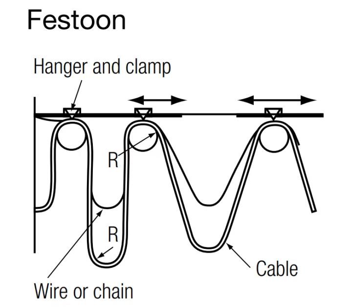
The fundamental distinction between FTNCT cables and other industrial cable categories centers on their operational environment and mechanical loading patterns. Festoon systems suspend cables along horizontal tracks using trolleys or carriers, subjecting cables to gravitational loading, lateral acceleration forces, and continuous flexing at relatively large radii compared to reeling applications. Chain-supported configurations employ similar principles but utilize chain elements rather than rigid track structures, offering enhanced flexibility for curved path applications while introducing additional torsional considerations.
Festoon System Operation Principles:
Festoon cable systems function as the bridge between stationary power sources and mobile equipment, employing trolleys that travel along fixed tracks to maintain proper cable management during equipment motion. The system comprises several essential components including cable trolleys that steer cables along tracks, festoon tracks forming the base structure for cable movement, cable hangers securing cables along the track path, and power supply units providing electrical connectivity. Festoon systems are distinguished from other electrification systems by their speed capabilities, weight management, and range of motion characteristics, with simple systems consisting of stationary clamp ends, control units shifting manually or automatically, and trolley series securing moving wires during machine operation.
FTNCT cables manufactured under JIS C 3327 specifications must satisfy rigorous requirements encompassing electrical performance parameters (voltage rating, insulation resistance, conductor resistance), mechanical durability characteristics (flex life, abrasion resistance, crush resistance), and environmental resilience factors (oil resistance, temperature tolerance, flame retardance). The elevated voltage rating of 0.6/1kV (U₀/U) compared to standard 600V specifications reflects European harmonization efforts while maintaining compatibility with Japanese industrial standards, facilitating global equipment interoperability across diverse crane manufacturing origins.
2. JIS C 3327 Standard Framework
JIS C 3327, formally titled “600 V Rubber Insulated Flexible Cables,” establishes the technical foundation for rubber-insulated flexible cables intended for Japanese industrial applications requiring mechanical durability combined with electrical reliability. Originally promulgated in 1993 by the Japanese Standards Association (JSA), this standard has undergone periodic revisions to incorporate technological advancements in materials science, testing methodologies, and international harmonization initiatives with IEC (International Electrotechnical Commission) standards.
The standard delineates comprehensive specifications across multiple cable categories, with festoon and chain cable classifications representing specialized subsets optimized for material handling applications. For FTNCT cables specifically, JIS C 3327 mandates enhanced mechanical performance parameters compared to general-purpose flexible cables, recognizing the severe operational demands of crane electrification systems. Testing protocols specified within the standard encompass voltage withstand tests, insulation resistance measurements, conductor resistance verification, flame retardance assessments, and accelerated aging evaluations to ensure long-term reliability.
JIS C 3327 Core Requirements for FTNCT Cables:
- Rated Voltage: U₀/U = 0.6/1kV (600V phase-to-ground, 1000V phase-to-phase)
- Dielectric Testing: 2500V AC applied for 5 minutes without breakdown
- Maximum Conductor Temperature: 90°C continuous operation (enhanced from standard 80°C)
- Short Circuit Temperature Limit: 250°C maximum for 5 seconds duration
- Minimum Bending Radius: 6D (six times cable diameter) for dynamic flexing
- Flame Retardance: JIS C 3005 horizontal flame test compliance required
- Conductor Construction: Class 5 or Class 6 stranding per IEC 60228
- Operating Temperature Range: -35°C to +90°C ambient conditions
The enhanced temperature rating of 90°C for FTNCT cables versus 80°C for standard JIS C 3327 cables reflects the implementation of improved insulation materials, specifically ethylene propylene rubber (EPR) compounds with optimized cross-linking densities and thermal stabilizer packages. This 10°C increase in continuous operating temperature provides substantial benefits including increased current-carrying capacity (approximately 7-10% higher ampacity at equivalent conductor sizes), extended service life under elevated ambient temperatures, and improved safety margins during transient overload conditions.
Insulation resistance requirements under JIS C 3327 mandate minimum values of 100 MΩ·km when measured at 20°C using DC test voltages of 500V for cables rated below 1kV. This specification ensures adequate electrical isolation between conductors and between conductors and ground under both dry and humid environmental conditions. Periodic insulation resistance testing during service life provides early warning indicators of potential insulation degradation, enabling proactive maintenance interventions before catastrophic failures occur.
3. Cable Variants: FTNCT, FTNCT-SB, FTNCT-PSB, FRCCT
3.1 FTNCT (Standard Festoon/Chain Cable)
FTNCT – Base Configuration
The standard FTNCT cable represents the fundamental festoon and chain cable design, incorporating essential features for reliable power transmission in material handling applications. This variant emphasizes mechanical robustness, electrical performance, and cost-effectiveness for general-purpose crane electrification where electromagnetic interference concerns remain minimal and data transmission requirements are absent.
Construction Characteristics:
- Conductor: Tinned copper, Class 5 or Class 6 stranding, sizes from 1.5mm² to 70mm²
- Insulation: EPR (Ethylene Propylene Rubber) compound, color-coded per JIS C 3662
- Filler: Synthetic fiber bundles or cotton threads for structural support
- Binder: Textile tape wrapping to maintain core assembly integrity
- Sheath: Chloroprene rubber (CR) or equivalent synthetic elastomer, nominal 2.0-2.5mm thickness
Typical Applications: Overhead traveling cranes, gantry cranes, monorail systems, jib cranes, automated storage/retrieval systems (AS/RS), conveyor systems, water treatment facilities, manufacturing production lines
3.2 FTNCT-SB (Shield Braid Variant)
FTNCT-SB – Electromagnetic Shielding Enhancement
FTNCT-SB cables incorporate braided metallic shields surrounding individual conductors or entire cable cores to mitigate electromagnetic interference (EMI) and radio frequency interference (RFI). This variant proves essential in environments with high electrical noise levels, proximity to variable frequency drives (VFDs), or installations requiring compliance with stringent electromagnetic compatibility (EMC) standards.
Shield Configuration Options:
- Individual Core Screening: Each conductor wrapped with braided tinned copper shield providing ≥60% optical coverage
- Overall Shield: Collective braided shield encompassing all cores with ≥80% coverage for maximum EMI protection
- Shield Material: Tinned copper wire braid, typical impedance 30Ω/km at 30 MHz measurement frequency
- Tape Layer: Non-woven fabric separator between shield and outer sheath preventing abrasion
Enhanced Construction Features:
The addition of electromagnetic shields increases overall cable diameter by approximately 8-12% compared to unshielded FTNCT equivalents while adding 15-20% to cable weight. Shield effectiveness typically achieves 40-50 dB attenuation at frequencies from 10 MHz to 1 GHz, sufficient for most industrial EMI mitigation requirements. Proper shield termination and grounding practices remain critical for realizing designed interference suppression performance, requiring continuous shield connection to equipment ground at one end (single-point grounding) or both ends (multi-point grounding) depending on application-specific considerations.
Applications Requiring FTNCT-SB: Automated manufacturing with robotic systems, facilities with extensive VFD usage, precision measurement and control systems, medical equipment manufacturing environments, telecommunications infrastructure, data centers with overhead cable management, research laboratories with sensitive instrumentation
3.3 FTNCT-PSB (Paired Shield Braid)
FTNCT-PSB – Data Transmission Optimization
FTNCT-PSB cables feature twisted pair conductor configurations with individual pair shielding, optimized for simultaneous power transmission and data communication applications. The paired conductor arrangement reduces differential mode noise coupling while individual pair shields provide common mode interference rejection, enabling reliable high-speed data transmission alongside power conductors within a single cable assembly.
Paired Conductor Specifications:
- Pair Configuration: Two conductors twisted together with controlled lay length (typically 25-50mm pitch)
- Pair Identification: Sequential numbering or color coding per pair for installation clarity
- Characteristic Impedance: Typically 100-120Ω for data pairs when specified
- Available Pair Counts: 6-pair, 9-pair, and custom configurations
- Conductor Sizes: Primarily 1.0mm², 1.5mm², and 2.5mm² for signal/control applications
Technical Performance Advantages:
Twisted pair construction with individual shielding achieves superior crosstalk rejection compared to parallel conductor arrangements, typically demonstrating near-end crosstalk (NEXT) values below -40 dB and far-end crosstalk (FEXT) below -50 dB at frequencies up to 100 MHz. This performance enables FTNCT-PSB cables to support industrial Ethernet protocols (PROFINET, EtherNet/IP, Modbus TCP), fieldbus systems (PROFIBUS, DeviceNet), and proprietary control networks requiring noise immunity in electrically harsh environments.
Applications: Smart crane systems with position feedback, automated guided vehicles (AGV) charging systems, Industry 4.0 manufacturing with integrated sensors, automated warehouse management systems, robotic pick-and-place operations, process control with distributed I/O modules
3.4 FRCCT (Fiber Optic Round Cable for Chain/Trolley)
FRCCT – Hybrid Fiber Optic Solution
FRCCT cables represent advanced hybrid designs integrating optical fiber transmission elements within mechanically robust cable structures suitable for festoon and chain applications. This configuration enables high-bandwidth data transmission immune to electromagnetic interference while maintaining the mechanical durability required for mobile crane applications. The designation FRCCT specifically indicates round cable geometry optimized for chain and trolley systems.
Optical Fiber Specifications:
| Fiber Type | Core Diameter (μm) | Cladding Diameter (μm) | Transmission Loss @ 850nm (dB/km) | Bandwidth @ 850nm (MHz·km) |
|---|---|---|---|---|
| GI 50/125 | 50 | 125 | ≤3.0 | ≥200 |
| GI 62.5/125 | 62.5 | 125 | ≤3.5 | ≥160 |
Hybrid Cable Construction:
- Optical Fiber Cord: Individual fibers contained within 2.8mm diameter protective tubes with aramid strength members
- Fiber Count: Typically 6 or 8 fibers, custom configurations available
- Tension Member: High-tensile polyester fiber braid or aramid yarn providing minimum 490N breaking strength
- Outer Sheath: Polyurethane (PUR) or halogen-free compound with enhanced UV resistance
- Bending Performance: 10D minimum radius maintains optical transmission integrity
Performance Characteristics:
FRCCT cables enable transmission distances exceeding 2 kilometers without signal regeneration, supporting data rates from 100 Mbps to 10 Gbps depending on fiber type and optical transmission equipment. The immunity to electromagnetic interference eliminates ground loop issues and electrical noise coupling concerns prevalent in copper-based communication systems. Optical fiber elements exhibit negligible signal attenuation degradation over cable service life, maintaining consistent transmission quality throughout 10-20 year operational periods.
Specialized Applications: High-speed automated container terminals, ship-to-shore (STS) cranes requiring video surveillance and SCADA data, automated rail-mounted gantry (RMG) cranes with precision positioning systems, smart port infrastructure with IoT integration, mining operations requiring explosion-proof data transmission, broadcast and entertainment rigging systems
4. Purpose and Applications
4.1 Festoon System Applications
Festoon cable systems serve as the predominant electrification method for overhead crane installations where lateral traverse motion spans significant distances, typically ranging from 10 to 200 meters of travel. Festoon cables are commonly used in material handling applications including overhead cranes, jib cranes, port cranes, and various equipment types, with these systems proving very stable for multiple indoor and outdoor applications under high temperatures and demanding conditions, including safe powering and control of explosion-proof cranes. The system architecture suspends cables from trolleys that roll along fixed C-rail tracks, I-beam flanges, or specialized festoon rails, maintaining proper cable routing throughout equipment motion while minimizing mechanical stress accumulation.
Primary Festoon System Applications:
- Overhead Bridge Cranes: Single and double-girder configurations spanning factory bays from 5 to 40 meters
- Gantry Cranes: Rail-mounted and rubber-tired variants for outdoor container handling and heavy manufacturing
- Monorail Systems: Suspended load handling in assembly lines and parts distribution centers
- Jib Cranes: Pillar-mounted and wall-mounted rotating cranes for localized material handling
- Automated Storage/Retrieval Systems (AS/RS): High-speed warehouse automation with vertical and horizontal motion
- Stacker Cranes: Automated warehouse equipment requiring precise positioning and high cycle rates
- Transfer Cars: Rail-guided material transport platforms in manufacturing facilities
- Grab Type Ship Unloaders: Bulk material handling equipment in port facilities
The selection between festoon and alternative electrification methods (conductor bars, cable reels, drag chains) depends on multiple factors including travel distance, speed requirements, environmental conditions, maintenance access, and capital budget constraints. Festoon systems offer advantages for applications requiring moderate speeds (typically 60-250 feet per minute), medium to heavy cable packages (supporting both power and control circuits), and installations where conductor bar systems prove impractical due to space constraints or environmental contamination concerns.
4.2 Chain-Supported Cable Systems
Chain-supported cable management systems represent an alternative to rigid festoon track installations, employing linked chain elements suspended along the cable route to support and guide cables during equipment motion. This approach offers several distinct advantages including simplified installation (particularly for retrofit applications), enhanced flexibility for curved path routing, reduced structural loading on building infrastructure, and cost-effectiveness for shorter travel distances (typically under 30 meters). Chain systems prove particularly valuable in applications where equipment mounting points change frequently or where temporary cable management solutions are required.
Chain System Operational Characteristics:
Cable support chains typically comprise plastic or steel links with integrated cable attachment points, dimensioned to accommodate specific cable diameters and weights. The chains suspend from fixed mounting points at both ends, forming a catenary curve that dynamically adjusts as equipment moves along its travel path. Proper chain tension adjustment proves critical for optimal performance, requiring sufficient sag to accommodate cable flexing while maintaining adequate ground clearance and preventing excessive dynamic motion during equipment operation.
4.3 Specialized Industrial Applications
Beyond conventional crane applications, FTNCT cables serve diverse specialized functions across various industrial sectors. Water and wastewater treatment facilities utilize festoon systems for traveling bridge scrapers, filter mechanisms, and automated screening equipment operating in corrosive environments with elevated humidity and chemical exposure. Automotive manufacturing plants employ extensive festoon networks supporting robotic welding systems, paint application equipment, and automated assembly line conveyors requiring reliable power delivery to mobile production machinery.
The steel industry presents particularly demanding applications where FTNCT cables must withstand extreme temperatures, exposure to scale and slag particles, and proximity to electromagnetic fields generated by induction heating systems and arc furnaces. Specialized high-temperature variants with enhanced insulation systems and heat-reflective sheath materials extend cable service life in these severe operating environments. Reeling cables designed for mobile machinery in port terminals and shipyards must endure dynamic motion, harsh environmental conditions including saltwater exposure and UV radiation, and heavy mechanical stress while ensuring reliable operations.
5. Key Characteristics and Performance Features
5.1 Superior Flexibility and Bending Resistance
FTNCT cables achieve exceptional flexibility through carefully engineered conductor stranding configurations, optimized insulation compound formulations, and balanced core assembly geometries. The minimum bending radius specification of 6D (six times overall cable diameter) for dynamic flexing applications represents a 33% improvement over conventional industrial cables typically requiring 9-10D bending radii. This enhanced flexibility proves critical in festoon applications where trolley spacing limitations and track geometry constraints often impose relatively tight cable routing radii.
Flex life testing per IEC 60227-2 procedures demonstrates FTNCT cable capability to withstand minimum 100,000 complete flexing cycles at 6D radius without conductor breakage or insulation cracking. Premium grade cables designed for high-cycle applications (automated warehouses, high-speed production lines) achieve flex lives exceeding 1,000,000 cycles through implementation of specialized conductor strand coatings, enhanced insulation elastomer formulations, and optimized core lay geometries that minimize differential stress concentration during cable bending.
Flexibility Performance Benchmarks:
- Conductor Stranding: Class 5 (>50 strands per mm²) or Class 6 (>80 strands per mm²) per IEC 60228
- Minimum Static Bending Radius: 6 × overall diameter (OD)
- Minimum Dynamic Bending Radius: 6 × OD with reduced flex life expectancy at tighter radii
- Flex Life Rating: ≥100,000 cycles at rated bending radius (standard duty)
- Torsion Resistance: ±90° twist per meter length without permanent deformation
- Recovery Characteristics: <5% permanent elongation after 100 flexing cycles
5.2 Wear and Tear Resistance with Tough Sheath
The outer sheath material selection fundamentally determines FTNCT cable resistance to mechanical abrasion, impact damage, and environmental degradation. Chloroprene rubber (CR, also marketed as Neoprene) serves as the predominant sheath compound for FTNCT applications, offering balanced properties including excellent abrasion resistance (typically <90 mm³ material loss per ISO 4649 testing), impact resistance maintaining integrity under -25°C ambient temperatures, and chemical resistance to oils, greases, and mild acids/bases encountered in industrial environments.
Abrasion resistance testing employing Taber abrader methods or DIN 53516 procedures quantifies material removal rates under standardized conditions. High-performance FTNCT cable sheaths demonstrate abrasion resistance indices of 120-150 mm³ (lower values indicating superior resistance), substantially exceeding PVC-sheathed cables (typical values 180-250 mm³) and approaching polyurethane performance levels (80-120 mm³) while maintaining superior environmental stress crack resistance and aging characteristics compared to polyurethane alternatives.
5.3 Superior Wiring Workability with Smooth Surface Sheath
Installation efficiency directly impacts project costs and schedule adherence, making cable handling characteristics a critical specification parameter. FTNCT cables feature smooth outer sheath surfaces achieved through precision extrusion processes utilizing carefully controlled die designs and temperature profiles. The smooth surface finish reduces friction during cable pulling through festoon trolley saddles, facilitates cable routing through cable clamps and support structures, and enables visual inspection for identifying surface damage or contamination accumulation.
Surface roughness measurements employing profilometer instrumentation typically demonstrate Ra values below 2.0 μm for premium FTNCT cables, compared to 3.5-5.0 μm for standard industrial cable sheaths. This improved surface finish reduces pulling forces during installation by 15-25%, enabling longer cable pulls without intermediate support structures and reducing labor hours required for installation activities. The smooth surface additionally resists contamination accumulation, maintaining aesthetic appearance and facilitating routine cleaning maintenance in food processing, pharmaceutical, and clean room applications.
5.4 Oil Resistance and Chemical Compatibility
Industrial crane environments frequently expose cables to hydraulic fluids, lubricating oils, cutting fluids, and various chemical contaminants. FTNCT cable sheath materials must demonstrate compatibility with these substances without suffering degradation of mechanical properties or electrical insulation characteristics. Oil resistance testing per IEC 60811-404 involves immersion in mineral oil at 100°C for 168 hours, followed by evaluation of tensile strength retention and volume change. Chloroprene rubber sheaths typically exhibit <25% volume swell and retain >70% of original tensile strength after oil immersion testing.
| Chemical/Substance | Resistance Rating | Maximum Concentration | Exposure Duration |
|---|---|---|---|
| Mineral Oil (Hydraulic) | Excellent | 100% | Continuous |
| Diesel Fuel | Good | 100% | Intermittent |
| Gasoline/Petrol | Fair | 100% | Limited (< 24hrs) |
| Cutting Fluids (Water-based) | Excellent | 100% | Continuous |
| Alkaline Solutions | Good | 10% | Intermittent |
| Acids (Dilute) | Good | 10% | Intermittent |
| Ozone | Excellent | N/A | Continuous |
5.5 Electrical Performance Characteristics
The enhanced voltage rating of 0.6/1kV (U₀/U notation indicates 600V phase-to-ground, 1000V phase-to-phase) provides substantial operational margins compared to standard 600V rated cables. This higher voltage rating accommodates potential network voltage variations (typically ±10% in industrial distribution systems), transient overvoltages from motor starting and switching operations, and provides safety factors reducing electrical stress on insulation systems. The 2500V AC dielectric test voltage represents a safety factor of 4.2:1 relative to 600V operating voltage, ensuring robust insulation integrity under normal and abnormal operating conditions.
Insulation resistance measurements at 500V DC test voltage must exceed 100 MΩ·km when measured at 20°C ambient temperature. This specification ensures adequate electrical isolation preventing leakage currents that could cause nuisance ground fault trips, excessive losses, or personnel safety hazards. Insulation resistance typically decreases with elevated temperature following an exponential relationship, with values at 90°C conductor temperature approximately 40-50% of 20°C measurements. Regular insulation resistance trending provides early warning of developing insulation degradation, enabling proactive maintenance interventions before failures occur.
6. Material Structure and Construction
6.1 Conductor Design and Materials
FTNCT cable conductors employ fine-stranded annealed copper conforming to Class 5 or Class 6 flexibility requirements per IEC 60228 specifications. For a 2.5mm² conductor, Class 5 stranding typically comprises 50-70 individual strands with diameters ranging from 0.21 to 0.26mm, while Class 6 stranding utilizes 80-120 strands with reduced individual strand diameters of 0.16 to 0.21mm. The finer stranding provides superior flexibility essential for festoon applications while maintaining adequate current-carrying capacity and mechanical strength.
Conductor material selection between bare copper and tinned copper involves trade-offs between cost, solderability, and corrosion resistance. Tinned conductors feature tin coating thickness typically 1-3 microns, providing enhanced oxidation resistance in humid environments, improved solderability for termination operations, and galvanic corrosion protection when interfacing with different metals. The tin plating adds approximately 3-5% to conductor cost while extending service life by 20-30% in corrosive industrial atmospheres, representing favorable cost-benefit economics for most applications.
6.2 Insulation System Engineering
Ethylene propylene rubber (EPR) serves as the primary insulation material for FTNCT cables rated at 90°C continuous operating temperature. EPR compounds offer superior thermal aging characteristics compared to natural rubber or PVC alternatives, maintaining mechanical properties and electrical integrity throughout extended service lives at elevated temperatures. The material exhibits excellent dielectric strength (typically >20 kV/mm), high volume resistivity (>10¹⁴ Ω·cm), and low dielectric loss factor (<0.005 at 50/60 Hz), ensuring minimal power losses and heat generation during current flow.
Insulation thickness selection follows established engineering formulas specified in IEC 60502 and related standards, balancing electrical stress considerations, mechanical protection requirements, and overall cable diameter optimization. For 0.6/1kV rated cables with conductor sizes from 1.5mm² to 6mm², typical insulation thickness ranges from 0.7 to 1.0mm. Larger conductor sizes (10mm² to 70mm²) employ proportionally increased insulation thickness, reaching 1.2 to 1.8mm for maximum sizes, maintaining electrical stress levels below 2.5 kV/mm under normal operating voltages.
FTNCT Cable Cross-Sectional Layer Structure:
- Conductor: Tinned or bare annealed copper, Class 5 or Class 6 stranding, Ø1.6-11.8mm depending on mm² rating
- Insulation: EPR compound, color-coded per JIS C 3662, thickness 0.7-1.8mm based on voltage and conductor size
- Filler: Synthetic fiber bundles (polypropylene or polyester) or cotton threads treated for moisture resistance
- Binder: Textile tape wrap (typically 50mm width, 50% overlap) maintaining core assembly during manufacturing
- Shield (FTNCT-SB/PSB only): Tinned copper braid, 60-80% optical coverage, typical impedance 30Ω/km @ 30 MHz
- Outer Sheath: Chloroprene rubber (CR) or CPE compound, black color, thickness 2.0-2.8mm providing mechanical and environmental protection
6.3 Core Assembly and Filler Materials
Following insulation application to individual conductors, cores are assembled into final cable configuration through cabling operations employing specified lay lengths and twist directions. For cables containing 12 cores or fewer, cores typically arrange in single layer circular configuration around a central filler element. Larger core counts (18-36 cores) employ multiple concentric layers with specific geometric arrangements optimizing cable circularity and minimizing differential stress during bending operations.
Filler materials occupy interstitial spaces between insulated cores, serving multiple critical functions including dimensional stability during manufacturing and handling, circular cross-section maintenance under bending, moisture barrier properties preventing water migration along cable length, and cushioning effects reducing mechanical stress transmission between cores. Traditional filler materials include cotton threads impregnated with moisture-resistant compounds, while modern cables increasingly employ polypropylene or polyester fiber bundles offering superior dimensional stability and moisture resistance.
6.4 Binder Tape Application
Following core assembly and filler placement, textile binder tapes wrap around the core bundle maintaining structural integrity during subsequent shielding and sheathing operations. Binder tapes typically comprise non-woven polyester fabrics with widths of 40-60mm, applied with 50% overlap and moderate tension (approximately 2-3 kg force) to consolidate cores without excessive compression. The binder layer additionally provides mechanical separation between metallic shields (when present) and insulated cores, preventing abrasion damage during cable flexing and vibration.
6.5 Sheath Material Formulation
Chloroprene rubber (CR) sheath compounds represent carefully engineered polymer blends incorporating multiple components beyond the base polymer. Typical formulations include chloroprene polymer (35-45% by weight), reinforcing fillers (carbon black, silica) providing mechanical strength (25-35%), plasticizers enhancing flexibility (10-15%), vulcanizing agents enabling cross-linking (3-5%), antioxidants preventing thermal degradation (1-2%), and flame retardants meeting fire safety requirements (5-10%). The precise formulation varies by manufacturer and specific application requirements, with premium compounds incorporating specialty additives for enhanced UV resistance, low-temperature flexibility, or specific chemical resistances.
Sheath extrusion employs pressure extrusion systems maintaining precise dimensional control and surface finish quality. Extrusion temperatures typically range from 80-110°C, with subsequent vulcanization conducted in continuous vulcanization (CV) lines at 180-220°C. The vulcanization process establishes three-dimensional cross-link networks within the elastomer structure, transforming thermoplastic material into thermoset rubber with permanent elastic properties and thermal stability enabling 90°C continuous operating temperatures.
7. Technical Specifications and Data Tables
7.1 FTNCT Standard Configuration Specifications
| Type | No. of Cores × Size (mm²) | Conductor Diameter (mm) | Nominal Overall Diameter (mm) | Maximum Overall Diameter (mm) | Approx. Weight (kg/km) |
|---|---|---|---|---|---|
| FTNCT | 3×4 | 3.0 | 14 | 14.7 | 300 |
| FTNCT | 3×6 | 3.2 | 16 | 16.8 | 400 |
| FTNCT | 3×10 | 4.2 | 19 | 20.0 | 610 |
| FTNCT | 3×16 | 5.7 | 23 | 24.2 | 900 |
| FTNCT | 3×25 | 7.1 | 27 | 28.4 | 1,330 |
| FTNCT | 3×35 | 8.3 | 31 | 32.6 | 1,760 |
| FTNCT | 3×50 | 9.9 | 35 | 36.8 | 2,310 |
| FTNCT | 3×35+3×16/3 | 8.3* | 31 | 32.6 | 1,890 |
| FTNCT | 3×50+3×25/3 | 9.9* | 35 | 36.8 | 2,480 |
| FTNCT | 3×70+3×35/3 | 11.8* | 42 | 44.1 | 3,550 |
| FTNCT | 4×4 | 3.0 | 16 | 16.8 | 360 |
| FTNCT | 4×6 | 3.2 | 17 | 17.9 | 480 |
| FTNCT | 4×10 | 4.2 | 21 | 22.1 | 760 |
| FTNCT | 4×16 | 5.7 | 25 | 26.3 | 1,110 |
| FTNCT | 4×25 | 7.1 | 30 | 31.5 | 1,650 |
| FTNCT | 4×35 | 8.3 | 34 | 35.7 | 2,210 |
| FTNCT | 4×50 | 9.9 | 39 | 41.0 | 2,920 |
| FTNCT | 5×4 | 3.0 | 17 | 17.9 | 435 |
| FTNCT | 5×6 | 3.2 | 19 | 20.0 | 575 |
| FTNCT | 5×10 | 4.2 | 23 | 24.2 | 910 |
| FTNCT | 5×16 | 5.7 | 28 | 29.4 | 1,350 |
| FTNCT | 5×25 | 7.1 | 34 | 35.7 | 2,010 |
| FTNCT | 12×1.5 | 1.6 | 19 | 20.0 | 465 |
| FTNCT | 12×2.5 | 2.1 | 22 | 23.1 | 660 |
| FTNCT | 18×1.5 | 1.6 | 22 | 23.1 | 645 |
| FTNCT | 18×2.5 | 2.1 | 26 | 27.3 | 915 |
| FTNCT | 24×1.5 | 1.6 | 25 | 26.3 | 855 |
| FTNCT | 24×2.5 | 2.1 | 30 | 31.5 | 1,210 |
| FTNCT | 30×1.5 | 1.6 | 27 | 28.4 | 1,020 |
| FTNCT | 30×2.5 | 2.1 | 32 | 33.6 | 1,480 |
| FTNCT | 36×1.5 | 1.6 | 29 | 30.5 | 1,200 |
| FTNCT | 36×2.5 | 2.1 | 35 | 36.8 | 1,760 |
* Power conductor diameter for combination cables with power + control cores
7.2 FTNCT-SB Shield Braid Variant Specifications
| Type | No. of Cores × Size (mm²) | Conductor Diameter (mm) | Nominal Overall Diameter (mm) | Maximum Overall Diameter (mm) | Approx. Weight (kg/km) |
|---|---|---|---|---|---|
| FTNCT-SB | 3×16+3×2.5 | 5.7* | 26 | 27.3 | 1,050 |
| FTNCT-SB | 3×25 | 7.1 | 30 | 31.5 | 1,410 |
| FTNCT-SB | 3×25+3×4 | 7.1* | 30 | 31.5 | 1,530 |
| FTNCT-SB | 3×35 | 8.3 | 34 | 35.7 | 1,820 |
| FTNCT-SB | 3×35+3×6 | 8.3* | 34 | 35.7 | 1,950 |
| FTNCT-SB | 3×50+3×10 | 9.9* | 38 | 39.9 | 2,750 |
| FTNCT-SB | 4×4 | 3.0 | 18 | 18.9 | 425 |
| FTNCT-SB | 4×6 | 3.2 | 20 | 21.0 | 525 |
| FTNCT-SB | 4×10 | 4.2 | 24 | 25.2 | 835 |
| FTNCT-SB | 4×35 | 8.3 | 37 | 38.9 | 2,290 |
| FTNCT-SB | 12×2.5 | 2.1 | 24 | 25.2 | 790 |
| FTNCT-SB | 20×2.5 | 2.1 | 29 | 30.5 | 1,160 |
| FTNCT-SB | 24×2.5 | 2.1 | 32 | 33.6 | 1,370 |
| FTNCT-SB | 30×2.5 | 2.1 | 34 | 35.7 | 1,640 |
| FTNCT-SB | 36×1.5 | 1.6 | 32 | 33.6 | 1,360 |
7.3 FTNCT-PSB Paired Shield Braid Specifications
| Type | No. of Pairs × Size (mm²) | Conductor Diameter (mm) | Minimum Overall Diameter (mm) | Maximum Overall Diameter (mm) | Approx. Weight (kg/km) |
|---|---|---|---|---|---|
| FTNCT-PSB | 6P×1 | 1.3 | 27 | 28.4 | 715 |
| FTNCT-PSB | 6P×1.5 | 1.6 | 29 | 30.5 | 825 |
| FTNCT-PSB | 6P×2.5 | 2.1 | 34 | 35.7 | 1,130 |
| FTNCT-PSB | 9P×1 | 1.3 | 35 | 36.8 | 1,120 |
| FTNCT-PSB | 9P×2.5 | 2.1 | 43 | 45.2 | 1,780 |
7.4 FRCCT Fiber Optic Cable Specifications
| Type | No. of Fibers | Fiber Type | Core/Clad (μm) | Cord Diameter (mm) | Overall Diameter (mm) | Weight (kg/km) | Tensile Load (N) |
|---|---|---|---|---|---|---|---|
| FRCCT-6G5032-V | 6 | GI | 50/125 | 2.8 | 15 | 220 | 490 |
| FRCCT-8G5032-V | 8 | GI | 50/125 | 2.8 | 17 | 260 | 490 |
| FRCCT-6G6242-V | 6 | GI | 62.5/125 | 2.8 | 15 | 220 | 490 |
| FRCCT-8G6242-V | 8 | GI | 62.5/125 | 2.8 | 17 | 260 | 490 |
7.5 Electrical and Thermal Parameters
| Parameter | Value | Test Standard | Notes |
|---|---|---|---|
| Rated Voltage U₀/U | 0.6/1kV AC | JIS C 3327 | 600V phase-to-ground, 1000V phase-to-phase |
| Test Voltage | 2500V AC / 5 minutes | JIS C 3327 | Applied between all conductors and ground |
| Insulation Resistance (20°C) | ≥100 MΩ·km | IEC 60885-3 | Measured at 500V DC |
| Max. Operating Temperature | 90°C | JIS C 3327 | Conductor temperature continuous rating |
| Short Circuit Temperature | 250°C (5 seconds max) | IEC 60364-5-52 | Maximum emergency overtemperature |
| Min. Installation Temperature | -35°C | Manufacturer spec | Ambient temperature during installation |
| Operating Temperature Range | -35°C to +90°C | JIS C 3327 | Full performance envelope |
| Flame Retardance | Pass JIS C 3005 horizontal | JIS C 3005 | Self-extinguishing when ignition source removed |
| Minimum Bending Radius (Fixed) | 6 × OD | IEC 60227-2 | Stationary installation minimum radius |
| Minimum Bending Radius (Dynamic) | 6 × OD | JIS C 3327 | Continuous flexing applications |
8. Comparison with VDE 0250-812 (German Standard)
VDE 0250-812 represents the German engineering approach to heavy-duty flexible cables for material handling applications, with particular emphasis on reeling cables rather than festoon-specific applications. The standard, titled “Cables, wires and flexible cords for power installation; rubber insulated flexible cable NSSHÖU,” addresses EPR-insulated cables rated at 450/750V. While both JIS C 3327 FTNCT and VDE 0250-812 NSSHÖU cables serve crane electrification applications, significant distinctions emerge from comparative technical analysis. High-quality cables manufactured with cutting-edge machinery establish benchmarks for structural integrity and performance consistency, with stringent quality control measures implemented at every stage from raw material inspection to finished product testing.
8.1 Comprehensive Standards Comparison
| Specification Parameter | JIS C 3327 FTNCT | VDE 0250-812 NSSHÖU |
|---|---|---|
| Geographic Origin | Japan (Asian Standard) | Germany (European Standard) |
| Voltage Rating | 0.6/1kV (U₀/U) | 450/750V (U₀/U) |
| Test Voltage Duration | 2500V AC / 5 minutes | 3000V AC / 15 minutes |
| Primary Application Focus | Festoon systems, chain-supported applications | Drum reeling, general heavy-duty applications |
| Max. Operating Temperature | 90°C | 80°C |
| Short Circuit Temperature | 250°C (5 seconds) | 250°C (5 seconds) |
| Conductor Class Options | Class 5 or Class 6 | Class 6 per VDE 0295 |
| Insulation Material | EPR compound | EPR per VDE 0207-21 |
| Sheath Material | CR (Chloroprene Rubber) | Polychloroprene per VDE 0207-20 |
| Ambient Temperature Range | -35°C to +90°C | -40°C to +80°C |
| Minimum Bending Radius | 6D (dynamic) | 5-8D depending on application |
| Flame Retardance Standard | JIS C 3005 horizontal test | IEC 60332-1-2 |
| Oil Resistance Testing | IEC 60811-404 (168h @ 100°C) | DIN VDE 0472-803 |
| Shield Options Available | FTNCT-SB, FTNCT-PSB variants | Not typically specified in base standard |
| Fiber Optic Integration | FRCCT variant standardized | Not addressed in VDE 0250-812 |
| Typical Weight (3×25mm²) | 1,330 kg/km | 1,450-1,600 kg/km |
| Smooth Surface Requirement | Explicitly specified | Not explicitly mandated |
| Core Identification Method | Per JIS C 3662 | HD 308 S2 color coding |
8.2 Technical Analysis and Application Implications
The voltage rating disparity between FTNCT (0.6/1kV) and NSSHÖU (450/750V) cables reflects different regional electrical distribution practices and equipment design philosophies. Japanese industrial standards traditionally specify higher nominal voltages to accommodate network variations and provide enhanced safety margins, whereas European standards emphasize precise voltage regulation within tighter tolerances. For practical crane applications operating at 380-480V three-phase systems, both cable types provide adequate voltage ratings with comparable safety factors.
The enhanced 90°C operating temperature rating of FTNCT cables versus 80°C for NSSHÖU variants delivers tangible performance advantages including approximately 8% higher current-carrying capacity for equivalent conductor sizes, improved overload tolerance during transient high-load conditions, extended service life in elevated ambient temperature environments (particularly relevant for subtropical and tropical climates), and reduced voltage drop under load due to lower conductor resistance at operating temperature.
Comparative Performance Assessment:
FTNCT Advantages:
- Higher operating temperature (90°C) enables increased ampacity and overload capacity
- Standardized shield variants (FTNCT-SB, FTNCT-PSB) address EMI/RFI requirements
- Integrated fiber optic solution (FRCCT) eliminates separate data cable requirements
- Optimized specifically for festoon system mechanical loading patterns
- Lighter weight (approximately 10-15% less for equivalent configurations)
- Explicit smooth surface requirement facilitates installation and maintenance
VDE 0250-812 NSSHÖU Advantages:
- Extended low-temperature capability (-40°C) for extreme cold climate applications
- More stringent voltage withstand test (15 minutes versus 5 minutes) ensures superior insulation reliability
- Comprehensive European standardization facilitating multi-national equipment interoperability
- Broader application versatility across reeling, festoon, and drag chain configurations
- Extensive field experience database spanning decades of industrial deployment
- Recognition across global crane manufacturers including Demag, Konecranes, Liebherr
From a materials science perspective, both standards specify comparable insulation and sheath compounds (EPR insulation, chloroprene/polychloroprene sheaths), though specific formulation details, additive packages, and cross-linking densities may vary between manufacturers and regional raw material supply chains. The conductor configurations exhibit similarity with both standards mandating Class 6 stranding for optimal flexibility, though specific strand counts, lay lengths, and conductor forming techniques may differ based on manufacturing equipment capabilities and process optimization strategies.
8.3 Market Selection Considerations
Equipment manufacturers and end-users face cable specification decisions influenced by multiple factors beyond pure technical performance. Regional crane manufacturer preferences significantly impact cable selection, with Asian-manufactured cranes (ZPMC, Mitsubishi, Mitsui, IHI) typically specifying JIS C 3327 FTNCT cables while European manufacturers (Konecranes, Demag, Liebherr, Terex) standardize on VDE 0250-812 compliant products. Existing installation base considerations favor maintaining consistent cable specifications to simplify spare parts inventory, standardize maintenance procedures, and leverage accumulated operational experience.
Cost considerations extend beyond initial procurement pricing to encompass total cost of ownership including installation labor (influenced by cable flexibility and handling characteristics), maintenance requirements (determined by durability and environmental resistance), service life expectancy (affecting replacement frequency and associated downtime costs), and energy efficiency (impacted by conductor resistance and current-carrying capacity). Comprehensive lifecycle cost analysis frequently reveals that premium cables with enhanced specifications deliver favorable economics despite higher initial costs through reduced maintenance requirements and extended service intervals.
9. Safety Thresholds and Standards Compliance
9.1 Electrical Safety Parameters and Protection Coordination
Electrical safety for FTNCT cable installations encompasses multiple protective layers designed to prevent shock hazards, fire risks, equipment damage, and operational disruptions. The fundamental safety mechanism involves robust insulation systems capable of withstanding operational voltages with substantial safety margins, evidenced by the 2500V AC test voltage representing a 4.2:1 safety factor relative to 600V operating voltage. This margin accommodates transient overvoltages from lightning-induced surges, switching transients, and motor starting inrush currents while maintaining insulation integrity throughout cable service life.
Critical Electrical Safety Thresholds:
- Maximum Continuous Voltage: 600V phase-to-ground, 1000V phase-to-phase (Do not exceed)
- Insulation Resistance Minimum: 100 MΩ·km at 20°C (Values below 50 MΩ·km warrant investigation)
- Conductor Temperature Limits: 90°C continuous, 250°C short-circuit (5 seconds maximum)
- Ground Fault Protection: RCD/GFCI with ≤30mA trip for personnel areas, ≤300mA for equipment protection
- Overcurrent Protection: Circuit breakers or fuses sized at 125-150% of cable ampacity
- Arc Fault Detection: Recommended for critical applications and enclosed spaces
- Thermal Overload Protection: Motor starters with Class 10 or Class 20 trip characteristics
Overcurrent protection device selection requires careful coordination with cable current-carrying capacity, ensuring protection devices operate before cable temperatures exceed safe limits during overload or short-circuit conditions. The current-carrying capacity (ampacity) of FTNCT cables depends on multiple factors including conductor size, number of loaded cores, installation method, ambient temperature, and grouping effects when multiple cables run in proximity. Derating factors must be applied for elevated ambient temperatures (typically 0.85 correction factor for 40°C ambient, 0.71 for 50°C ambient) and cable bundling (0.80-0.85 for 2-3 cables in contact).
9.2 Mechanical Safety and Structural Integrity
Mechanical safety in festoon and chain cable applications encompasses proper support system design, cable routing optimization, and dynamic loading analysis. Festoon trolley systems must accommodate cable weight plus dynamic forces generated during equipment acceleration/deceleration, with trolley load ratings typically specified at 40-150 pounds depending on application class. Insufficient trolley capacity leads to premature wear, binding, and potential cable dropout from support structures creating trip hazards and operational disruptions.
| Safety Parameter | Minimum Requirement | Recommended Safety Factor | Inspection Frequency |
|---|---|---|---|
| Festoon Trolley Load Rating | ≥1.5× static cable weight | 2.0-2.5:1 for dynamic loading | Monthly visual inspection |
| Track Mounting Strength | ≥3× total suspended load | 4:1 minimum | Annual structural assessment |
| Cable Clamp Torque | Per manufacturer specification | N/A (precision required) | Quarterly verification |
| Bend Radius Compliance | ≥6× cable OD | 8-10× OD optimal | Installation verification, annual audit |
| Ground Continuity | <0.5Ω end-to-end | <0.1Ω for critical applications | Quarterly testing |
| Track Alignment | ±5mm vertical, ±10mm horizontal | ±2mm vertical, ±5mm horizontal | Annual survey |
9.3 Fire Safety and Emergency Response
Fire safety requirements mandate flame-retardant cable constructions complying with JIS C 3005 horizontal flame test or equivalent international standards (IEC 60332-1-2). These tests verify cables self-extinguish when ignition sources are removed, preventing fire propagation along cable routes. For applications in high-occupancy buildings, transportation tunnels, or enclosed spaces, additional requirements may include low smoke emission characteristics (IEC 61034 testing) and halogen-free compound formulations minimizing toxic gas generation during fire events.
Emergency response planning for festoon cable installations should address potential failure scenarios including cable dropout from trolley systems, electrical fault conditions causing arc flash hazards, and mechanical impacts from mobile equipment. Emergency procedures must define safe shutdown sequences, electrical isolation methods, firefighting approaches appropriate for electrical fires, and personnel evacuation protocols. Regular emergency drills ensure personnel familiarity with procedures and identify improvement opportunities before actual emergencies occur.
9.4 Regulatory Compliance Documentation
Comprehensive cable documentation packages facilitate regulatory compliance verification and support long-term maintenance planning. Essential documentation includes type test reports demonstrating JIS C 3327 compliance across all electrical and mechanical parameters, material composition certificates verifying conductor purity and insulation/sheath compound formulations, fire performance test results with certification body accreditation, RoHS/REACH compliance declarations for hazardous substance restrictions, manufacturer installation and maintenance guidelines, and warranty terms defining coverage periods and exclusions.
Required Documentation Checklist:
- Type test certificate per JIS C 3327 from accredited laboratory
- Material composition certificates for all cable components
- Fire performance test reports (JIS C 3005 or IEC 60332-1-2)
- Oil resistance test data (IEC 60811-404 methodology)
- RoHS compliance declaration for European Union markets
- REACH substance registration documentation
- Manufacturer installation manual with technical specifications
- Warranty certificate defining coverage terms and conditions
- Traceability documentation linking delivered cable to test reports
10. Precautions for Use and Installation
10.1 Pre-Installation Planning and Site Assessment
Successful FTNCT cable installations begin with comprehensive planning addressing site-specific conditions, equipment specifications, and operational requirements. Site surveys should document ambient temperature ranges (both operational and storage), presence of corrosive atmospheres or chemical contamination, electromagnetic interference sources requiring shielded cable variants, available installation access for cable delivery and routing, structural capacity for festoon track mounting loads, and electrical distribution system characteristics including voltage levels, fault current magnitudes, and grounding configurations.
Equipment specification review ensures cable selection matches crane electrical requirements including motor power ratings and starting currents determining conductor sizing, control circuit voltage and current requirements influencing core count selections, operational duty cycle affecting thermal loading and flex life requirements, travel distances establishing total cable length requirements, and speed profiles determining dynamic loading on festoon systems. Consultation with crane manufacturers provides valuable insights into recommended cable specifications and installation practices optimized for specific equipment models.
10.2 Installation Best Practices
Critical Installation Guidelines:
- Temperature Considerations: Install only when ambient temperature exceeds -5°C to prevent temporary stiffening and insulation damage. For cables stored below 0°C, condition at room temperature for minimum 24 hours before installation.
- Handling Procedures: Support cable reels on appropriate axles with adequate load capacity. Never drop, impact, or drag cables across rough surfaces. Maintain minimum bending radii during all handling operations.
- Pulling Tension Limits: Restrict pulling forces to maximum 50 N/mm² of total conductor cross-section. Use pulling grips distributing forces evenly across cable circumference, never pull on individual conductors.
- Festoon Track Alignment: Maintain track alignment within ±5mm vertical and ±10mm horizontal tolerances. Misalignment increases trolley wear and cable mechanical stress.
- Trolley Spacing: Position trolleys at intervals preventing excessive cable sag (typically 1.0-1.5 meter spacing for standard duty applications, 0.6-1.0 meter for heavy-duty or high-speed installations).
- Cable Clamp Installation: Tighten saddle clamps to manufacturer-specified torque values. Over-tightening crushes cable structure, while under-tightening allows cable slippage and wear.
- Termination Quality: Use proper terminal lugs sized for conductor cross-section. Apply anti-oxidant compounds on aluminum terminals. Maintain proper crimping force per manufacturer specifications.
- Electrical Continuity: Verify ground conductor continuity throughout cable length and connection integrity to equipment grounding systems. Ground resistance should not exceed 0.5Ω end-to-end.
10.3 Operational Precautions and Monitoring
During normal operations, several factors require continuous or periodic monitoring to prevent premature cable failure and ensure personnel safety. Operational staff training should emphasize recognition of abnormal conditions including unusual cable positioning or routing deviations, visible insulation damage or sheath cracking, discoloration indicating overheating, excessive vibration or swinging motion, and electrical anomalies such as ground fault alarms or circuit breaker nuisance tripping.
Load Management: Continuous operation above 80% of rated cable ampacity requires periodic temperature monitoring verifying conductor temperatures remain below 90°C threshold. Infrared thermography provides non-invasive temperature assessment identifying hot spots caused by loose terminations, unbalanced loading, or insulation degradation. Consider ambient temperature derating factors, particularly in tropical climates or enclosed spaces where enclosure temperatures may exceed 40°C significantly reducing cable current-carrying capacity.
Environmental Protection: While FTNCT cables incorporate oil-resistant sheaths, minimize direct exposure to concentrated petroleum products, aggressive solvents, and corrosive chemicals. Implement regular cleaning programs removing contamination accumulation from cable surfaces and festoon track components. Inspection following chemical spills or unusual environmental exposures enables early detection of potential degradation before catastrophic failures occur.
10.4 Maintenance Program Implementation
Systematic preventive maintenance programs significantly extend cable service life while reducing unexpected failure risks. Maintenance activities should align with equipment operational intensity, with high-cycle applications (automated warehouses, high-speed production lines) requiring more frequent inspections compared to intermittent-duty installations (maintenance cranes, auxiliary handling equipment).
| Maintenance Activity | Frequency – Standard Duty | Frequency – Heavy Duty | Acceptance Criteria |
|---|---|---|---|
| Visual Inspection | Monthly | Weekly | No visible damage, proper cable routing |
| Trolley Condition Assessment | Quarterly | Monthly | Wheels rotate freely, no excessive wear |
| Track Alignment Verification | Semi-annually | Quarterly | Within ±5mm vertical, ±10mm horizontal |
| Electrical Testing (IR, continuity) | Semi-annually | Quarterly | IR ≥100 MΩ·km, ground <0.5Ω |
| Thermographic Survey | Annually | Semi-annually | No hot spots >15°C above ambient |
| Comprehensive System Audit | Annually | Annually | All parameters within specifications |
| Festoon Cleaning | Semi-annually | Quarterly | Free from contamination accumulation |
10.5 Storage Requirements for Spare Cables
Proper storage of spare cable inventory preserves material properties and ensures readiness for emergency replacements. Store cable drums or reels in covered, dry facilities avoiding direct sunlight exposure accelerating sheath degradation through UV radiation. Maintain storage temperatures between 0°C and 40°C with relative humidity below 75%. Position drums vertically on flat surfaces preventing deformation, or horizontally on axle supports if vertical storage proves impractical. Rotate inventory quarterly implementing first-in-first-out (FIFO) practices, particularly for cables stored longer than 12 months. Inspect stored cables annually for surface deterioration, checking flexibility by unrolling short sections and verifying no hardening or cracking has occurred during storage.
11. Common Problems and Troubleshooting
11.1 Cable Snagging and Trolley Binding
Symptoms: Cable fails to follow equipment motion smoothly, trolleys bind or stop rolling freely, excessive force required for equipment movement, visible cable damage at trolley contact points.
Root Causes: Festoon track misalignment exceeding tolerance specifications, trolley wheel bearing failure or excessive wear, foreign object contamination in track channels, improper cable clamp adjustment allowing slippage, incompatible cable diameter relative to trolley saddle dimensions, or inadequate trolley spacing causing excessive cable loops.
Diagnostic Procedures: Measure track alignment using laser alignment tools or precision levels. Inspect trolley wheel condition checking for flat spots, cracks, or rough rotation. Clean track channels removing accumulated debris, metal filings, or hardened lubricant. Verify cable clamp torque and adjustment. Confirm trolley saddle inner dimensions accommodate cable outer diameter with appropriate clearance (typically 2-5mm).
Solutions: Realign festoon track within specified tolerances using shimming or bracket adjustment. Replace worn or damaged trolley wheels and bearings. Implement regular track cleaning program preventing contamination accumulation. Adjust cable clamps to proper tension preventing slippage without excessive compression. Replace trolleys with correct saddle dimensions if cable diameter incompatibility exists. Optimize trolley spacing based on cable weight and stiffness characteristics.
11.2 Premature Sheath Wear and Abrasion
Symptoms: Visible sheath wear patterns at trolley contact points, surface cracking or checking, color fading indicating UV degradation, localized thinning progressing toward insulation layer exposure.
Root Causes: Excessive cable motion within trolley saddles from improper adjustment or inadequate trolley spacing, abrasive contamination (metal chips, concrete dust, sand) accumulating on cable surfaces or in trolley channels, chemical exposure to incompatible substances attacking sheath polymer, UV radiation degradation in outdoor installations without adequate sheath stabilization, operation beyond recommended temperature limits accelerating aging processes.
Solutions: Adjust cable clamps ensuring positive retention without over-compression. Increase trolley population reducing span lengths and limiting cable movement amplitude. Implement comprehensive cleaning program addressing both cable surfaces and festoon system components. Identify and eliminate sources of chemical contamination, considering protective barriers or rerouting if exposure continues. For outdoor installations experiencing severe UV exposure, consider upgrading to cables with enhanced UV stabilizer packages or implementing protective covers over exposed cable sections. Monitor operational temperatures ensuring compliance with 90°C conductor limit and -35°C minimum ambient specification.
11.3 Conductor Breakage and Continuity Loss
Symptoms: Intermittent or complete loss of electrical function in one or more phases/control circuits, increased conductor resistance evidenced by voltage drop measurements or heating, electrical testing revealing open circuits or elevated resistance values.
Root Causes: Flex fatigue from excessive bending cycles, particularly at tighter-than-specified radii, overload conditions exceeding conductor current capacity causing thermal damage, mechanical damage from external impacts or crushing, manufacturing defects in conductor stranding or assembly, corrosion of conductor strands in environments with moisture ingress through damaged sheath, vibration-induced fatigue at termination points lacking adequate strain relief.
Diagnostic Techniques: Employ time-domain reflectometry (TDR) testing to locate fault positions with precision typically within 1-2 meters. Conduct detailed electrical testing measuring conductor resistance phase-by-phase comparing against specification values. Perform visual inspection at cable terminations and mid-span locations checking for signs of mechanical damage or overheating. Review operational logs identifying overload events or equipment malfunctions potentially subjecting cables to abnormal stresses.
Solutions: For localized conductor failure, replace affected cable section if splice accessibility permits, or replace entire cable run if fault location or multiple failures indicate systemic issues. Verify festoon system geometry ensures bend radius compliance throughout travel range. Review loading calculations confirming conductor sizing adequacy for actual operational currents including motor starting transients. Implement enhanced strain relief at termination points distributing mechanical stress over longer distances. If premature failures persist, investigate manufacturing quality through destructive testing of failed cable sections and consider alternative suppliers or enhanced specifications.
11.4 Insulation Degradation and Ground Faults
Symptoms: Declining insulation resistance measurements trending downward over successive tests, increased ground fault current indicated by protective device operation or leakage current monitoring, visible insulation damage or tracking patterns, unusual odors suggesting overheating or chemical degradation.
Root Causes: Moisture ingress through sheath damage creating conductive paths, chemical contamination attacking insulation compounds, thermal aging from chronic overloading or inadequate ventilation, electrical stress concentration at manufacturing defects or damage sites, mechanical damage compromising insulation integrity.
Diagnostic Approach: Conduct comprehensive electrical testing including insulation resistance at multiple test voltages (250V, 500V, 1000V DC) documenting values and establishing trends. Perform dissipation factor (tan δ) measurements providing early indication of insulation deterioration before resistance values decline significantly. Execute high-potential (hi-pot) testing at controlled voltages identifying weak spots or developing failures. Implement partial discharge testing for critical applications detecting corona or tracking phenomena preceding catastrophic breakdown.
Solutions: For localized insulation damage with intact conductors, temporary repairs using self-amalgamating tape and heat-shrink overmolding may provide short-term restoration, though permanent replacement remains preferable. Address root causes including moisture sources, chemical exposures, or thermal management deficiencies. Implement enhanced monitoring programs for aging cable populations including quarterly insulation resistance trending and annual comprehensive electrical testing. Plan systematic replacement schedules for cables approaching end-of-life based on age, operational intensity, and test result trends rather than waiting for catastrophic failures creating unplanned downtime.
11.5 Electromagnetic Interference Issues
Symptoms: Control system malfunction or erratic behavior, communication network errors or data corruption, sensor reading anomalies, PLC input/output glitches, increased error rates in data transmission.
Root Causes: Inadequate electromagnetic shielding in installations with high electrical noise environments, improper shield grounding practices creating ground loops or leaving shields floating, parallel routing of power and control cables allowing inductive/capacitive coupling, proximity to VFD installations or other high-frequency noise sources, shield damage or discontinuity compromising effectiveness.
Solutions: Upgrade to FTNCT-SB or FTNCT-PSB shielded cable variants providing inherent interference immunity. Verify shield grounding employs proper single-point grounding (for lower frequencies) or multi-point grounding (higher frequencies/longer cable runs) methodology. Separate power and control/data cables maintaining minimum spacing distances (typically 300mm for unshielded cables, reduced to 150mm for shielded types). Install line filters or reactors at VFD outputs reducing conducted emissions. Employ optical isolation or fiber optic transmission (FRCCT cables) for critical signals requiring maximum noise immunity. Conduct electromagnetic compatibility (EMC) assessment using spectrum analyzers identifying specific interference sources and frequencies enabling targeted mitigation strategies.
When to Replace Rather Than Repair:
- Conductor failures exceeding 10% of total core count indicating systemic problems
- Insulation resistance below 50 MΩ·km with continuing downward trend
- Extensive sheath damage exposing insulation over >25% of cable length
- Cable age exceeding 15 years in continuous duty or 20 years in light duty service
- Multiple previous repairs indicating recurring failure mechanisms
- Failure of voltage withstand testing at standard test voltages
- Evidence of severe thermal damage (melted insulation, discolored conductors)
- Incompatibility with upgraded equipment requiring higher specifications
Contact Anhui Feichun Special Cable Co., Ltd.
For FTNCT cable specifications, customization, technical support, or quotations:
[email protected]
[email protected]
+86 13855 123218
Available 24/7 for emergency technical support. Providing OEM/ODM solutions worldwide.
12. References and Citations
- Japanese Industrial Standards (JIS). (1993). JIS C 3327:1993 – 600 V Rubber Insulated Flexible Cables. Japanese Standards Association, Tokyo, Japan. Available at: https://www.jsa.or.jp/
- German Institute for Standardization (DIN). (1985). DIN VDE 0250-812:1985 – Cables, wires and flexible cords for power installation; rubber insulated flexible cable NSSHÖU. VDE Verlag GmbH, Berlin, Germany.
- Nante Crane. (2024). Festoon Cable Systems Explained – Types, Benefits and Applications. Retrieved from: https://www.nantecrane.com/news/festoon-cable-systems-explained-types-benefits-and-applications/
- Ocean Middle East LLC. (2023). A Festoon Cable System Overview – Types & Parts. Retrieved from: https://ocean-me.com/festoon-cable-system/
- Technomax Middle East. (2024). What Is A Festoon Cable System? Types And Benefits. Retrieved from: https://www.technomaxme.com/festoon-cable-system/
- Reeling Cable. (2024). Understanding Reeling Cables for Mobile Machinery in Port Terminals and Shipyards. Retrieved from: https://reelingcable.com/
- Amplex Mining. (2024). Feichun AS/NZS Mining Cables Manufacturer Excellence. Retrieved from: https://amplexmining.com.au/
- International Electrotechnical Commission (IEC). (2011). IEC 60228:2011 – Conductors of insulated cables. IEC Central Office, Geneva, Switzerland.
- International Electrotechnical Commission (IEC). (2012). IEC 60811-404:2012 – Electric and optical fibre cables – Test methods for non-metallic materials – Part 404: Miscellaneous tests – Mineral oil immersion tests for sheaths. IEC Central Office, Geneva, Switzerland.
- International Electrotechnical Commission (IEC). (2013). IEC 60332-1-2:2004+AMD1:2015 – Tests on electric and optical fibre cables under fire conditions – Part 1-2: Test for vertical flame propagation for a single insulated wire or cable – Procedure for 1 kW pre-mixed flame. IEC Central Office, Geneva, Switzerland.
- Conductix-Wampfler. (2024). Cable Festoon Systems – C-Track and Stretch Wire Rope Solutions. Technical catalog. Retrieved from: https://www.conductix.us/en/products/cable-festoon-systems
- Prysmian Group. (2024). Round Low Voltage Cables for Festoon Operation – Technical Data Sheet. Product documentation. Retrieved from: https://www.prysmian.com/sites/default/files/business_markets/markets/downloads/datasheets/Festoon.pdf
- Grand Ocean Marine. (2024). Exploring Festoon Cable Specifications: An In-Depth Examination. Retrieved from: https://www.grandoceanmarine.com/festoon-cable-specifications/
- International Organization for Standardization (ISO). (2015). ISO 9001:2015 – Quality management systems – Requirements. ISO Central Secretariat, Geneva, Switzerland.
- International Electrotechnical Commission (IEC). (2015). IEC 60364-5-52:2009+AMD1:2015 – Low-voltage electrical installations – Part 5-52: Selection and erection of electrical equipment – Wiring systems. IEC Central Office, Geneva, Switzerland.
- Anhui Feichun Special Cable Co., Ltd. (2024). FTNCT Festoon and Chain Cable Technical Documentation and Manufacturing Specifications. Internal engineering documentation and type test reports.


