
Understanding NSHTÖU, TSCGEWÖU, and PUR Polyurethane Cables – Technical Specifications, Standards Compliance, Selection Criteria, and GB/T 5013 Limitations
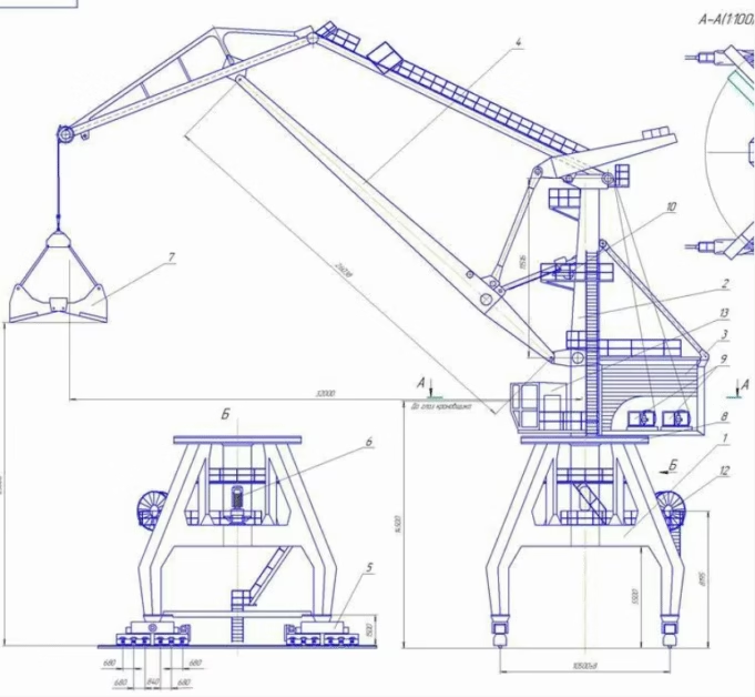
Reeling Drum Cables for Port Cranes and Material Handling: Complete Engineering Guide
Understanding NSHTÖU, TSCGEWÖU, and PUR Polyurethane Cables – Technical Specifications, Standards Compliance, Selection Criteria, and GB/T 5013 Limitations
By Anhui Feichun Special Cable Co., Ltd. (安徽飞纯特种电缆有限公司)
Leading manufacturer of specialized reeling cables for container cranes, gantry cranes, stacker-reclaimers, and heavy-duty port equipment worldwide
1. Introduction: Understanding Reeling Drum Cable Technology
In the demanding world of port logistics, container handling, and heavy material movement, the electrical cables that power mobile equipment represent far more than simple current-carrying conductors. These specialized cables must simultaneously withstand extreme mechanical stresses that would quickly destroy conventional power cables, including continuous tensile loads from their own suspended weight, torsional stresses as they wind and unwind from rotating drums, and dynamic acceleration forces as massive cranes accelerate and decelerate while moving containers at speeds reaching 300 meters per minute. Understanding the engineering principles, material science, and standardized designs that enable these cables to survive in such harsh environments is essential for equipment manufacturers, port operators, and maintenance engineers responsible for keeping critical cargo handling systems operational.
This comprehensive technical guide examines three distinct families of reeling drum cables that dominate modern port and material handling applications. First, we explore the NSHTÖU cable family (standardized under DIN VDE 0250-814) which includes variants optimized for different grounding configurations and vertical versus horizontal reeling applications. These low voltage cables rated at 0.6/1 kV represent the workhorse solution for most crane control and auxiliary power circuits. Second, we analyze medium and high voltage reeling cables in the voltage range from 3.6/6 kV up to 20 kV and beyond, designated as (N)TSCGEWÖU under German standard DIN VDE 0250-813. These cables deliver primary power to massive gantry cranes and stacker-reclaimers, often incorporating integrated fiber optic elements for high-speed data transmission alongside power conductors. Third, we examine the emerging PUR (polyurethane) sheathed reeling cables that offer significant advantages in weight, diameter, and abrasion resistance compared to traditional rubber-sheathed designs, making them particularly attractive for high-speed container handling equipment.
Finally, and perhaps most importantly for engineers familiar with conventional Chinese cable standards, we must address why standard GB/T 5013 YCW cables prove unsuitable for serious reeling drum applications despite their widespread use in other mobile equipment applications. This discussion helps engineers understand the critical importance of anti-torsion construction elements that prevent the catastrophic “lantern effect” deformation and conductor breakage that occurs when cables without proper torsional resistance are subjected to repeated winding cycles on high-speed reeling drums. Through detailed analysis supported by field failure data and technical testing results, this guide provides the engineering foundation necessary to specify, install, and maintain reeling cable systems that deliver reliable service life measured in years rather than months.
1.1 The Unique Challenges of Reeling Drum Applications
To appreciate why specialized reeling cables exist as a distinct product category, we must first understand the extreme mechanical environment these cables experience during normal operation. Consider a typical ship-to-shore container crane with a reeling drum cable system. As the crane’s trolley travels along the boom to pick up and deposit containers, the cable continuously winds onto and unwinds from a rotating drum, typically mounted at the waterside end of the crane structure. The drum may be configured as either a monospiral design where the cable forms a single layer on the drum surface, or as a multilayer cylindrical reel where cables stack on top of each other1.
During this reeling operation, the cable experiences multiple simultaneous stress modes that simply do not occur in fixed installation or even festoon system applications. The tensile stress arises from the cable supporting its own weight in the suspended section between the drum and the cable entry point on the moving trolley. For long boom cranes with cable runs exceeding 100 meters, this suspended weight can impose tensile loads of 2,000 kilograms or more on the cable structure. Without proper reinforcement elements to carry these tensile loads, the copper conductors themselves would stretch and eventually fracture from the repeated loading and unloading cycles2.
The torsional stress component proves even more insidious and less intuitive to engineers unfamiliar with reeling applications. As the cable winds onto a rotating drum, each point along the cable’s length experiences a twisting force. Imagine holding one end of a rope while someone else winds the opposite end onto a spindle – the rope naturally wants to twist along its length. In cable applications, this twisting force must be resisted by the cable’s internal structure; otherwise, the cable will develop a helical deformation where conductors spiral around each other, creating the characteristic “lantern” or “birdcage” appearance that signals imminent failure. Testing conducted by European cable manufacturers on cables without proper anti-torsion protection shows that such cables develop visible torsional deformation after fewer than 10,000 reeling cycles, while properly constructed reeling cables survive more than 500,000 cycles in the same test regime3.
⚠️ Critical Design Requirement: Anti-Torsion Construction
The single most important distinguishing feature of genuine reeling drum cables versus ordinary flexible power cables lies in the incorporation of anti-torsion elements within the cable structure. These elements typically consist of textile braiding (polyamide or aramid) positioned between the inner cable core and the outer sheath, creating a structural layer that resists twisting forces. The braid transfers torsional loads to the outer sheath rather than allowing them to concentrate in the conductor bundle, preventing the helical deformation that leads to conductor breakage.
Standard mobile cables including GB/T 5013 YCW, YC, and even YCW variants lack this critical anti-torsion braiding layer. They may appear suitable based on voltage rating, conductor size, and flexibility characteristics, but their use in reeling drum applications represents a fundamental engineering error that will result in premature failure. Field failure reports from port facilities that mistakenly specified YCW cables for gantry crane applications document cable lifespans of only 6-18 months before conductor fracture necessitates replacement, compared to 5-8 year lifespans achieved with proper NSHTÖU or TSCGEWÖU cables in identical service conditions4.
2. NSHTÖU Low Voltage Reeling Cable Family (0.6/1 kV)
2.1 Cable Designation and Variant Nomenclature
The NSHTÖU designation follows German cable naming conventions where each letter conveys specific technical information about the cable’s construction and intended application. Breaking down this designation letter by letter reveals the cable’s complete specifications: “N” indicates a standard conductor configuration (the prefix “(N)” in some variants indicates that the earth conductor can be optionally omitted). “SH” specifies heavy-duty rubber sheath construction using Type 5GM3 rubber compound defined in DIN VDE 0207 Part 21. “T” denotes the presence of anti-torsion protection, specifically a textile braid integrated between cable layers. “Ö” indicates oil resistance meeting the requirements of DIN VDE 0473-811-404. “U” confirms UV resistance and weather protection suitable for outdoor installations5.
This base designation NSHTÖU can be further modified with suffix letters to denote specific variant configurations optimized for different application requirements. Understanding these variants helps engineers select the most appropriate cable type for their specific crane installation.
NSHTÖU-J Cable
Designation Meaning: The suffix “J” (from German “Ja” meaning “yes”) indicates that this variant includes a dedicated green/yellow earth (ground) conductor integrated within the cable structure.
Conductor Configuration: Typically specified as “N+1” where N represents the number of power and control conductors and the “+1” denotes the separate earth conductor. For example, a cable might be designated as 4×25mm² + 1×16mm², indicating four power conductors of 25mm² cross-section plus one earth conductor of 16mm² cross-section6.
Application Suitability: This represents the standard variant for most crane power supply applications where electrical safety codes require a dedicated protective earth conductor separate from the power conductors. The earth conductor size is typically calculated as a proportion of the phase conductor size, commonly ranging from 50% to 100% of the phase conductor cross-section depending on fault current calculations.
NSHTÖU-O Cable
Designation Meaning: The suffix “O” (from German “Ohne” meaning “without”) indicates that this variant excludes the dedicated earth conductor. The cable consists solely of power and/or control conductors.
Conductor Configuration: Specified as a simple count of conductors, such as 4×25mm² with no additional earth conductor. In systems using this variant, the equipment frame or a separate earth conductor external to the cable provides the grounding function.
Application Suitability: Less common in modern installations due to electrical safety requirements, but may be found in older equipment or in applications where the crane structure itself provides the earth return path. Some control cable applications where the controlled equipment has its own earth connection may also use this variant to reduce cable bulk and weight. Cost savings compared to NSHTÖU-J variant typically amount to 8-12% for equivalent conductor sizes7.
NSHTÖU-V Cable
Designation Meaning: The suffix “V” (from German “Vertikal” meaning “vertical”) indicates enhanced construction specifically engineered for vertical reeling applications where cables hang predominantly in a vertical orientation rather than horizontal.
Enhanced Features: This variant incorporates significantly stronger central support elements, typically using aramid (Kevlar) yarn or steel wire rope capable of supporting higher tensile loads. The reinforcement allows the cable to safely carry its own weight over longer vertical distances without imposing excessive stress on the copper conductors. Maximum tensile loads may reach 50 N/mm² compared to the standard 20 N/mm² rating of horizontal reeling variants8.
Application Suitability: Essential for container crane spreader cables where the cable drops vertically from the trolley to the container spreader attachment, often spanning 20-30 meters or more. Also used in ship unloader boom applications and high-lift gantry cranes where vertical cable spans are substantial. The enhanced tensile strength comes at a cost premium of approximately 25-35% over standard NSHTÖU-J cables.
2.2 Material Construction and Layer Analysis
Understanding the detailed layer-by-layer construction of NSHTÖU cables provides insight into how these cables achieve their remarkable combination of flexibility, strength, and durability. Let us examine each structural element in sequence from the innermost conductors outward to the protective sheath, understanding both what each layer consists of and why it performs its specific function.
Layer 1: Fine-Stranded Copper Conductors
The conductors utilize superfine bare copper stranding meeting Class 5 specifications per IEC 60228 and DIN VDE 0295. Individual wire diameters range from 0.10mm to 0.25mm depending on total conductor cross-section, with strand counts ranging from 32 strands for 1.0mm² conductors up to 800+ strands for conductors of 95mm² and larger. The fine stranding provides the flexibility essential for reeling applications while maintaining adequate conductor current capacity9.
Many manufacturers specify tinned copper conductors rather than bare copper, particularly for marine and offshore applications. The tin plating (typically 1-2 micrometers thick) prevents copper oxidation that could increase contact resistance at termination points, and provides some protection against corrosion in humid environments. However, tinning does reduce conductor flexibility slightly due to the additional stiffness of the tin layer.
Layer 2: Core Insulation – EPR Rubber Compound
Individual conductors receive insulation consisting of ethylene propylene rubber (EPR) compounds designated as Type 3GI3 or similar formulations per DIN VDE 0207. This rubber insulation provides excellent electrical properties with volume resistivity exceeding 1×10¹⁴ Ω·m, combined with superior mechanical properties including tensile strength above 10 MPa and elongation at break exceeding 200%. The EPR formulation maintains flexibility across the cable’s rated temperature range of -40°C to +90°C10.
Conductor color coding follows HD 308 S2 standards for core identification. Power conductors typically use brown, black, and grey colors for phases, with blue for neutral (where applicable) and green/yellow stripes for earth. Control conductors receive black insulation with white number printing for identification purposes.
Layer 3: Inner Sheath – Rubber Compound Type 5GM3
After individual insulated conductors are laid together (typically stranded around a central textile or aramid support element), an inner sheath of special rubber compound Type 5GM3 or 5GM2 encapsulates the conductor bundle. This inner sheath serves multiple critical functions: it holds conductors in their designed geometric arrangement preventing displacement during flexing, it provides a smooth surface for the anti-torsion braid to bear against, and it contributes additional mechanical protection for the conductor insulation11.
The rubber compound formulation includes plasticizers for flexibility, stabilizers for heat and UV resistance, and flame retardant additives to meet IEC 60332-1 flame propagation test requirements. Compound thickness typically ranges from 1.5mm to 3.0mm depending on total cable diameter.
Layer 4: Anti-Torsion Protection – Textile Braid
This critical layer distinguishes reeling cables from standard flexible power cables. The anti-torsion element consists of an open-weave textile braid manufactured from polyamide (nylon) threads, aramid fibers, or occasionally fiberglass. The braid typically features a mesh pattern with openings of 2-4mm that allows the outer sheath rubber to flow through during manufacture, creating mechanical interlocking between the braid and both the inner and outer rubber layers12.
The braid’s function is to resist cable twisting by distributing torsional loads circumferentially rather than allowing them to concentrate axially along the conductor bundle. When the cable experiences twisting force during reeling, the braid engages mechanically with both rubber layers, transferring the torque to the cable’s outer diameter rather than allowing the conductor core to rotate relative to the sheath.
Layer 5: Outer Sheath – Polychloroprene (Neoprene) Compound
The final protective layer consists of heavy-duty polychloroprene rubber (commonly known by the trade name Neoprene) meeting Type 5GM3 compound specifications. This material provides outstanding resistance to oils, chemicals, UV radiation, ozone, and weathering. Shore A hardness typically measures 65-75, providing good abrasion resistance while maintaining adequate flexibility. Outer sheath thickness varies with cable size but generally ranges from 2.5mm to 5.5mm for standard configurations13.
The black color serves both practical and technical purposes. Practically, black cables show dirt and contamination less obviously than lighter colors, important for industrial environments. Technically, carbon black pigment provides excellent UV protection, absorbing ultraviolet radiation before it can degrade the polymer chains in the rubber compound. For specific customer requirements, colored outer sheaths (commonly yellow, orange, or grey) can be manufactured using alternative pigmentation and UV stabilizer packages.
| Cable Size | Rated Voltage U₀/U | Conductor Material | Insulation Type | Sheath Material | Max. Conductor Temp | Ambient Temp Range |
|---|---|---|---|---|---|---|
| 1.5 – 400 mm² | 0.6/1.0 kV | Tinned copper Class 5 | EPR Type 3GI3 | Polychloroprene 5GM3 | +90°C | -40°C to +60°C (fixed) -25°C to +60°C (flexing) |
2.3 Technical Performance Specifications
| Performance Parameter | Specification Value | Test Standard | Significance |
|---|---|---|---|
| Maximum Operating Voltage AC | 1.2 kV | DIN VDE 0250-814 | Rated voltage 0.6/1 kV with safety margin |
| Maximum Operating Voltage DC | 1.8 kV | DIN VDE 0250-814 | Higher DC voltage allowable due to reduced insulation stress |
| High Voltage Test | 4.0 kV AC / 5 min | DIN VDE 0250 Part 815 | Factory production test validates insulation integrity |
| Insulation Resistance | ≥50 MΩ·km @ 20°C | DIN VDE 0295 | High IR confirms low leakage current |
| Minimum Bending Radius (Fixed) | 8 × D | DIN VDE 0298 Part 3 | D = overall cable diameter; tighter bends risk damage |
| Minimum Bending Radius (Dynamic) | 12 × D | DIN VDE 0298 Part 3 | Larger radius required for repeated flexing cycles |
| Maximum Tensile Load (Standard) | 20 N/mm² | DIN VDE 0250-814 | Based on conductor cross-sectional area |
| Maximum Tensile Load (NSHTÖU-V) | 50 N/mm² | Manufacturer specification | Enhanced for vertical reeling applications |
| Travel Speed (Horizontal Reeling) | Up to 120 m/min | DIN VDE 0250-814 | Standard speed rating for monospiral reels |
| Travel Speed (Festoon Systems) | Up to 240 m/min | Manufacturer specification | Higher speed possible when not under reeling stress |
| Flame Retardancy | Passes single cable test | VDE 0482-332-1-2 IEC 60332-1 | Self-extinguishing after flame removal |
| Oil Resistance | Passes 168h @ 70°C | DIN VDE 0473-811-404 | Suitable for exposure to industrial oils |
3. Medium and High Voltage Reeling Cables (3.6/6 kV to 20 kV+)
3.1 (N)TSCGEWÖU Cable Family – Power Transmission Cables
When port cranes and material handling equipment require primary power at medium voltage levels, the cable requirements escalate dramatically compared to low voltage applications. The (N)TSCGEWÖU designation represents a family of cables specifically engineered for these challenging applications, manufactured according to German standard DIN VDE 0250 Part 813 and European standard HD 620 S2. The designation breaks down as follows: “N” indicates normal conductor count (prefix “(N)” indicates earth conductor may be omitted), “TSC” denotes cable with conductor screen and insulation screen layers, “GE” specifies rubber insulation type, “W” confirms weather and UV resistance, “Ö” indicates oil resistance, and “U” denotes suitability for outdoor installations14.
These cables power the primary motor drives of large gantry cranes, ship-to-shore container cranes, and stacker-reclaimers where the electrical equipment operates at distribution voltages rather than low voltage. The most common voltage ratings include 3.6/6 kV (maximum system voltage 7.2 kV), 6/10 kV (maximum system voltage 12 kV), 8.7/15 kV (maximum system voltage 17.5 kV), and 12/20 kV (maximum system voltage 24 kV). Custom voltage ratings up to 30 kV are available for specialized applications15.
Critical Medium Voltage Construction Features
The distinguishing characteristic of medium voltage cables lies in the incorporation of semiconductive screening layers that control electrical field distribution within the insulation system. Understanding why these screens exist and how they function is essential to appreciating medium voltage cable technology. In cables operating above 1 kV, the electric field intensity within the insulation becomes high enough that any discontinuities or irregularities in the conductor-to-insulation interface can create localized field concentrations that lead to partial discharge activity and eventual insulation breakdown.
To prevent this failure mechanism, medium voltage cables incorporate a semiconductive layer between the conductor and the main insulation, and another semiconductive layer between the insulation and the metallic earth screen or sheath. These layers are manufactured from rubber compounds containing carbon black or other conductive additives that give them resistivity values typically in the range of 10 to 500 Ω·m – high enough to prevent significant current flow, but low enough to ensure they remain equipotential with their adjacent conductors or ground plane. This creates smooth, controlled electric field distribution without the sharp gradient concentrations that would otherwise exist at material interfaces16.
Layer Structure of (N)TSCGEWÖU Cables
Working from the center outward, these cables consist of fine-stranded Class 5 copper conductors, an inner semiconductive screen layer, main EPR insulation (designated Type 3GI3 or EI6 depending on manufacturer), an outer semiconductive screen, a copper wire screen for electrical shielding and fault current return, an inner rubber sheath for mechanical protection, a polyamide or aramid anti-torsion braid, and finally a heavy-duty outer rubber sheath. The outer sheath typically uses red-colored compound to provide immediate visual distinction from low voltage cables, reducing the risk of mistaken identity during maintenance operations17.
The copper wire screen deserves particular attention as it serves multiple critical functions. First, it provides an electrical shield that contains the cable’s electric field within the cable structure, preventing external electromagnetic interference and reducing capacitive coupling to nearby conductors. Second, it serves as the earth conductor, providing a low-impedance fault current return path essential for protective relay operation. Third, it contributes mechanical strength to resist abrasion and impact damage. The screen typically consists of 0.3mm to 0.7mm diameter copper wires applied helically over the insulation screen with coverage factors ranging from 80% to 95% depending on application requirements18.
| Voltage Rating | Insulation Thickness | Conductor Screen | Insulation Screen | Typical Application |
|---|---|---|---|---|
| 3.6/6 kV (U₀/U) | 2.5 mm | Semiconductive EPR | Semiconductive EPR | Small to medium gantry cranes, rail-mounted equipment |
| 6/10 kV | 3.4 mm | Semiconductive EPR | Semiconductive EPR | Container handling cranes, larger stackers |
| 8.7/15 kV | 4.5 mm | Semiconductive EPR | Semiconductive EPR | Large ship-to-shore cranes, bulk handlers |
| 12/20 kV | 5.5 mm | Semiconductive EPR | Semiconductive EPR | Extra-large container cranes, industrial facilities |
3.2 (N)TSKCGECWÖU Cables – Power Plus Fiber Optic Integration
Modern automated port facilities require not only electrical power delivery but also high-bandwidth data communication between the crane control system and various sensors, cameras, and monitoring equipment distributed throughout the crane structure. Traditionally, this would require running separate fiber optic cables alongside power cables, creating installation complexity and vulnerability to damage during crane operation. The (N)TSKCGECWÖU cable family solves this challenge by integrating fiber optic elements directly within the power cable structure, creating a single unified cable that delivers both power and data in one robust package19.
The fiber optic elements are protected within a dedicated channel or tube located in the center of the cable, surrounded by the power conductors. This central location provides maximum protection from mechanical stress and bending forces. The fiber tube typically contains multiple individual fibers, with standard offerings including 6, 12, 18, or 24 fibers depending on the data transmission requirements of the installation. Both multimode fibers (typically 50/125 or 62.5/125 micrometer core/cladding dimensions) for shorter distances and campus-scale systems, and single-mode fibers (9/125 micrometer) for longer distances and higher bandwidth requirements are available20.
✓ Application Example: Automated Container Terminal
Consider a modern automated container terminal with remotely operated rail-mounted gantry (RMG) cranes. Each crane requires 6 kV three-phase power delivered through a reeling cable system, plus high-speed data communication for:
Multiple HD cameras providing operator vision and automated positioning feedback (requiring 100-300 Mbps bandwidth per camera), laser scanning sensors for container detection and positioning (10-50 Mbps per sensor), the crane control system PLC communicating with terminal operations center (10-50 Mbps), and diagnostic and monitoring systems transmitting real-time performance data. The total bandwidth requirement easily exceeds 1 Gbps, necessitating fiber optic communication.
A single (N)TSKCGECWÖU cable with 3 power cores of 95mm² for the three-phase supply, plus integrated 12-fiber multimode optical tube, replaces what would otherwise require a separate power cable and fiber optic cable run. This integration reduces installation complexity, eliminates one potential failure point (the separate fiber cable), and ensures that power and communication move together as a unified system. Field experience from major ports including Rotterdam, Hamburg, and Singapore demonstrates that integrated power-fiber cables achieve 30-40% lower total cost of ownership compared to separate cable installations when accounting for initial installation costs, maintenance requirements, and reduced downtime from cable failures21.
3.3 Performance Specifications and Operating Parameters
| Parameter | TSCGEWÖU Specification | TSKCGECWÖU (w/ Fiber) | Test Standard |
|---|---|---|---|
| Voltage Ratings Available | 3.6/6 kV to 18/30 kV | 3.6/6 kV to 12/20 kV | DIN VDE 0250-813 |
| Conductor Material | Bare copper Class 5 | Bare copper Class 5 | IEC 60228 |
| Insulation Material | EPR Type EI6 (super-clean) | EPR Type EI6 | DIN VDE 0207 |
| Semiconductive Screens | Inner & outer EPR-based | Inner & outer EPR-based | DIN VDE 0207 |
| Conductor Operating Temp | +90°C continuous | +90°C continuous | DIN VDE 0250-813 |
| Short Circuit Temperature | +250°C (max 5 seconds) | +250°C (max 5 seconds) | DIN VDE 0250-813 |
| Ambient Temp (Fixed Install) | -50°C to +80°C | -50°C to +80°C | Manufacturer rating |
| Ambient Temp (Flexing) | -35°C to +80°C | -35°C to +80°C | Manufacturer rating |
| Max Tensile Load | 20 N/mm² | 20 N/mm² (30 N/mm² acceleration) | DIN VDE 0250-813 |
| Min Bending Radius | 15 × D (fixed), 20 × D (dynamic) | 15 × D (fixed), 20 × D (dynamic) | DIN VDE 0298 Part 3 |
| Max Travel Speed | Up to 300 m/min | Up to 240 m/min | Manufacturer specification |
| Outer Sheath Color | Red (standard) / custom | Red (standard) | Visual identification |
| Fiber Optic Count | N/A | 6, 12, 18, or 24 fibers | Customer specification |
| Fiber Type Options | N/A | MM 50/125, MM 62.5/125, SM 9/125 | ITU-T G.651/G.652 |
4. PUR Polyurethane Sheathed Reeling Cables (Trommelflex/Drum Flex)
4.1 Understanding Polyurethane Cable Technology
While rubber-sheathed cables like NSHTÖU and TSCGEWÖU have served the crane industry reliably for decades, polyurethane (PUR) sheathed cables represent an important technological evolution that offers significant performance advantages for specific applications, particularly high-speed container handling equipment operating in modern automated terminals. To understand why PUR cables have gained substantial market share in recent years, we must examine the fundamental material properties that differentiate polyurethane from conventional rubber compounds22.
Polyurethane is a thermoplastic elastomer, meaning it combines the elastic properties of rubber with the processing advantages of thermoplastics. At room temperature, PUR behaves mechanically like rubber with excellent flexibility and resilience. However, unlike thermoset rubbers (EPR, EPDM, polychloroprene) which undergo irreversible cross-linking during manufacture, polyurethane can be repeatedly heated and reformed. This thermoplastic character does not typically matter for cable applications since cables are not reprocessed, but it reflects the different molecular structure that gives PUR its distinctive property profile23.
4.2 Comparative Advantages of PUR vs. Rubber Sheaths
🎯 Superior Abrasion Resistance
Standardized abrasion testing using Taber abraders demonstrates that PUR sheaths lose approximately 40-50% less material mass than equivalent polychloroprene rubber sheaths when subjected to identical test cycles. This translates directly to longer service life in applications where cables experience repeated contact with guide rollers, drum surfaces, or structural members. Field data from container terminals shows PUR-sheathed cables achieving service lives of 8-12 years compared to 5-7 years for rubber equivalents in identical reeling drum applications24.
⚖️ Reduced Weight and Diameter
PUR compounds typically exhibit densities of 1.15-1.25 g/cm³ compared to 1.40-1.55 g/cm³ for polychloroprene rubber. This 15-20% density advantage, combined with PUR’s superior mechanical properties allowing thinner sheath walls to achieve equivalent protection levels, results in overall cable weight reductions of 25-35% for PUR cables compared to rubber equivalents. For long cable runs exceeding 150 meters, this weight reduction significantly decreases the tensile load the cable structure must support, potentially allowing the use of cables without steel wire reinforcement where rubber cables would require it25.
🌡️ Improved Low-Temperature Performance
High-quality PUR compounds maintain flexibility to temperatures as low as -40°C or even -50°C in specialized formulations, matching or exceeding the low-temperature capability of rubber sheaths. However, PUR retains better impact resistance at these extreme temperatures, showing less tendency to crack or fracture if struck while cold. This makes PUR cables particularly suitable for container terminals in cold climates where cables may experience both cold temperatures and mechanical impacts26.
🔧 Enhanced Notch Resistance
Once a cut or nick penetrates the surface of a cable sheath, the critical question becomes whether that defect will propagate under stress or remain localized. PUR demonstrates superior tear propagation resistance compared to rubber, with standardized tear strength tests showing PUR requires 50-80% more force to propagate an existing cut. This property is particularly valuable in applications where cables may experience surface damage from sharp edges or debris, as minor damage is less likely to develop into major failures27.
🧪 Chemical Resistance Profile
PUR exhibits excellent resistance to mineral oils, greases, many solvents, and dilute acids/bases. The resistance to aliphatic hydrocarbons matches or exceeds that of polychloroprene rubber. However, PUR shows reduced resistance to aromatic hydrocarbons (benzene, toluene), strong acids, and alkaline solutions compared to specialized rubber formulations. Port environments typically contain primarily mineral-based hydraulic fluids and greases, making PUR’s resistance profile well-matched to application requirements28.
⚡ Hydrolysis Considerations
Standard PUR formulations based on polyester polyols can experience hydrolytic degradation when exposed to high temperature and humidity over extended periods, with tropical climates representing the worst-case scenario. This chemical breakdown weakens the polymer structure and reduces mechanical properties. Modern PUR cables for marine and port applications utilize polyether-based polyurethane formulations that demonstrate significantly improved hydrolysis resistance. Manufacturers specify that polyether-based PUR cables survive accelerated aging tests (95% humidity at 70°C for 1000 hours) with less than 15% loss of mechanical properties, qualifying them for long-term outdoor use in humid climates29.
4.3 Application Profiles: When to Specify PUR Cables
Optimal PUR Cable Applications
PUR-sheathed reeling cables deliver maximum value in several specific application profiles where their advantages outweigh their higher initial cost (typically 30-45% premium over rubber-sheathed equivalents). High-speed container handling cranes operating at travel speeds exceeding 180 m/min benefit from PUR’s reduced weight and superior abrasion resistance, as the decreased cable mass reduces dynamic loads on the reeling drum and support structures. Automated stacking cranes (ASC) and rail-mounted gantry (RMG) cranes in climate-controlled warehouses or indoor terminals can fully exploit PUR’s performance advantages without concern for UV degradation or hydrolysis issues that may affect outdoor rubber cables.
Retrofit and modernization projects where existing reeling drums and motors must accommodate new cables benefit from PUR’s smaller diameter and lighter weight, often allowing capacity upgrades without modifying mechanical infrastructure. Applications requiring frequent cable replacement due to high duty cycles see PUR’s extended service life translated into reduced maintenance costs and downtime. Space-constrained installations where cable storage drums have limited capacity favor PUR’s compact dimensions, potentially allowing longer cable runs within existing drum sizes30.
| Property | Polychloroprene Rubber (NSHTÖU) | Polyurethane (Trommelflex PUR) | Advantage |
|---|---|---|---|
| Abrasion Resistance (Taber test) | Mass loss 200-250 mg | Mass loss 100-130 mg | PUR 40-50% better |
| Density | 1.40-1.55 g/cm³ | 1.15-1.25 g/cm³ | PUR 15-20% lighter |
| Tensile Strength | 12-18 MPa | 35-50 MPa | PUR significantly higher |
| Tear Strength | 25-35 N/mm | 60-90 N/mm | PUR 2-3× better |
| Shore A Hardness | 65-75 | 85-95 | PUR harder (better abrasion resistance) |
| Operating Temp Range | -40°C to +90°C | -40°C to +90°C | Equivalent |
| UV Resistance | Excellent (carbon black) | Good (requires UV stabilizers) | Rubber slightly better for outdoor |
| Hydrolysis Resistance | Excellent | Good (polyether-based PUR) | Rubber better in humid tropics |
| Mineral Oil Resistance | Excellent | Excellent | Equivalent |
| Flame Retardancy | Good (with additives) | Excellent (halogen-free formulations) | PUR better for enclosed spaces |
| Relative Cost | Baseline (1.0×) | 1.3-1.45× | Rubber lower initial cost |
5. Critical Analysis: Why GB/T 5013 YCW Cables Fail in Reeling Applications
⚠️ ENGINEERING WARNING: Improper Cable Specification
This section addresses a common and costly specification error that continues to cause premature cable failures in port equipment and material handling installations worldwide. Engineers unfamiliar with reeling cable requirements sometimes specify standard Chinese heavy-duty rubber cables (GB/T 5013 series, particularly YCW cables) for reeling drum applications based on seemingly similar specifications including voltage rating, conductor size, rubber construction, and oil resistance. This represents a fundamental misunderstanding of reeling cable engineering requirements that results in cable service lives measured in months rather than years, along with expensive emergency replacements and production downtime.
5.1 Understanding GB/T 5013 YCW Cable Construction
To understand why YCW cables prove unsuitable for reeling applications, we must first examine their designed purpose and construction. The GB/T 5013 standard (which parallels IEC 60245) specifies rubber-insulated and rubber-sheathed flexible cables for rated voltages up to 450/750V intended for use in portable equipment, mobile machinery, and temporary installations. The YCW designation indicates: “Y” for mobile cable, “C” for heavy-duty construction, and “W” for weather and oil resistance31.
YCW cables employ stranded copper conductors (typically Class 5 flexibility), rubber insulation on individual cores, rubber inner sheath around the conductor bundle, and oil-resistant rubber or chloroprene outer sheath. On paper, this construction appears suitable for mobile equipment applications. Indeed, YCW cables perform excellently in their designed applications including portable power tools, welding machine feeds, festoon systems with limited travel, and mobile equipment with flexible trailing cables that do not undergo reeling. The critical difference lies in what YCW cables lack rather than what they contain.
5.2 The Missing Element: Anti-Torsion Structure
The fundamental deficiency of YCW cables for reeling applications is the complete absence of anti-torsion protection elements in their construction. GB/T 5013 does not specify or require textile braiding, aramid reinforcement, or any other structural element designed to resist torsional forces. The cable consists simply of conductors, insulation, and sheath layers with no intermediate reinforcement. This construction proves perfectly adequate for applications where the cable flexes but does not experience the rotational stresses inherent in reeling operations32.
When a YCW cable is installed on a reeling drum and subjected to winding and unwinding cycles, the absence of torsional resistance allows the cable structure to twist along its length. This twisting does not occur uniformly; instead, it concentrates in the areas of highest flexibility, typically the mid-span sections between the drum and the cable termination point. Over repeated cycles, this accumulated torsion causes the conductors to spiral around each other in a helical pattern, eventually creating the characteristic “lantern” or “birdcage” deformation visible from outside the cable as the sheath takes on a wrinkled, accordion-like appearance in localized sections33.
5.3 Failure Mechanisms and Timeline
Progressive Failure Progression in YCW Cables on Reeling Drums
Phase 1 (0-5,000 cycles): Initial operation appears normal with no external signs of distress. Internally, however, torsional forces begin accumulating in the cable structure. The inner sheath between insulated conductors begins experiencing increased stress as conductors shift position during each reeling cycle.
Phase 2 (5,000-15,000 cycles): Careful external inspection may reveal slight surface irregularities or “ripples” in the cable sheath, particularly in mid-span sections. Internal examination (if cable were sectioned) would show that conductor spacing has become non-uniform with some cores clustering together while gaps open between others. The inner sheath shows signs of compression in areas where conductors bunch together and stretching in areas where they separate.
Phase 3 (15,000-30,000 cycles): External “lantern” deformation becomes clearly visible with localized areas showing severe wrinkling or ballooning of the outer sheath. Internally, conductors have developed significant helical displacement with some cores winding around others. Individual conductor insulation begins showing stress cracks in areas of maximum bending and compression. Electrical symptoms may include intermittent power interruptions or control signal failures as conductors experience increased resistance or momentary open circuits during movement34.
Phase 4 (30,000-50,000 cycles): Complete conductor breakage occurs, typically beginning with the smallest cross-section conductors (control circuits) before progressing to power conductors. The cable becomes unusable and must be replaced. For context, a crane operating 8 hours per day at 15 meters per minute average speed with a 100-meter cable run experiences approximately 720 reeling cycles per day, reaching 50,000 cycles in just 70 operating days or roughly 3-4 months of service.
5.4 Field Experience Documentation
Case studies from port facilities document the consequences of YCW cable misapplication. A container terminal in Southeast Asia specified YCW 4×95mm² + 12×4mm² cables for rail-mounted gantry crane applications, selecting them based on apparent cost savings compared to specified NSHTÖU cables (approximately 40% lower procurement cost). The installation operated for only 4.5 months before experiencing the first cable failure, manifesting as intermittent control system malfunctions. Detailed failure analysis revealed advanced lantern deformation and two fractured control conductors. Over the following two months, four additional cables failed across the fleet of six cranes. Total cost including emergency cable procurement at premium prices, crane downtime during replacements, and lost terminal productivity exceeded eight times the initial savings from selecting YCW instead of properly specified reeling cables35.
Similar reports emerge from mining operations, steel mills, and other industries where engineers unfamiliar with reeling cable requirements selected YCW cables for drum-based power distribution. The failure pattern remains remarkably consistent across different installations: apparent satisfactory performance for 2-6 months followed by rapid failure progression requiring emergency replacement. This experience contrasts sharply with properly specified NSHTÖU or TSCGEWÖU cables that routinely achieve 5-10 year service life in identical applications.
5.5 Limited Acceptable Applications for YCW in Mobile Equipment
This analysis should not be interpreted as suggesting YCW cables have no legitimate use in mobile equipment – quite the contrary. YCW cables excel in numerous applications including low-speed material handling where linear travel without reeling occurs (electric platform trucks, slow-moving overhead cranes with festoon systems under 0.5 m/s, portable equipment with trailing cables), short-distance reeling applications with minimal travel (small electric hoists with cable runs under 10 meters, adjustable height work platforms with limited vertical travel), and temporary installations where cables require frequent disconnection and relocation. In these applications, YCW’s combination of durability, oil resistance, and cost-effectiveness makes it an excellent choice36.
The key determining factor is whether the cable experiences continuous reeling operation where torsional stresses accumulate over tens of thousands of cycles. For equipment operating fewer than 100 reeling cycles per day in low-duty-cycle service, YCW cables may provide acceptable service life. However, for any equipment approaching or exceeding 500 cycles per day, specification of proper reeling cables with anti-torsion construction is not optional but mandatory for achieving acceptable reliability and avoiding premature failures.
| Feature | GB/T 5013 YCW Cable | DIN VDE 0250 NSHTÖU Cable | Impact on Reeling Applications |
|---|---|---|---|
| Anti-Torsion Braiding | ❌ Not present | ✅ Polyamide/aramid braid standard | Critical for preventing lantern deformation |
| Central Support Element | ❌ Optional, often omitted | ✅ Textile/aramid core standard | Carries tensile load, prevents conductor stretch |
| Design Standard | GB/T 5013 (IEC 60245) | DIN VDE 0250-814 | VDE 0250 specifically addresses reeling stresses |
| Reeling Cycle Rating | Not specified (not designed for reeling) | >500,000 cycles tested | Defines operational lifetime expectancy |
| Travel Speed Rating | Not specified | Up to 120 m/min (horizontal reeling) | High speeds amplify torsional stress effects |
| Typical Service Life (Reeling) | 3-8 months before failure | 5-10 years in proper application | Dramatic difference in total cost of ownership |
| Purchase Price (Relative) | Baseline (1.0×) | 1.6-2.0× (initial cost) | YCW appears cheaper but fails quickly |
| Cost per Operating Year | 3-4× NSHTÖU cost | Baseline (1.0×) | YCW much more expensive over lifetime |
Industry Resources and Technical Partners
For specialized reeling cable solutions, engineering support, and application expertise across port facilities, mining operations, and heavy industrial environments:
Complete reeling cable portfolio – NSHTÖU to medium voltage
Specialized reeling drum cable engineering and design
Port crane and material handling cable systems
Heavy-duty trailing and reeling cables for mining
Australian mining and industrial cable specialist
Technical Standards, References, and Supporting Documentation
- Reeling drum cable mechanical stress analysis and cable configuration types. Tratos Group – Reeling Cables Technical Overview
- Tensile load calculations for suspended reeling cables in long-boom crane applications. HT Wire Cable – TSCGEWÖU Specifications
- Comparative torsional stress testing of reeling cables with and without anti-torsion protection. Crane Cable – NSHTÖU Comparison Study
- Field failure analysis documenting premature failure of non-reeling-rated cables in drum applications. Port facility maintenance records and cable manufacturer field service reports.
- DIN VDE 0250-814 standard specifications for NSHTÖU cable construction and designation system. Eland Cables – NSHTÖU Technical Documentation
- NSHTÖU-J cable conductor configuration and earth conductor sizing requirements. HuaDong Cable – NSHTOEU-J Specifications
- NSHTÖU-O variant applications and cost analysis. Mueller Group – NSHTÖU Product Overview
- NSHTÖU-V vertical reeling cable enhanced tensile strength specifications. Eland Cables – NSHTÖU Variants
- IEC 60228 and DIN VDE 0295 conductor stranding class specifications. AllKabel – NSHTÖU Construction Details
- EPR insulation material properties and electrical performance characteristics. Honest Cable – NSHTOU Technical Parameters
- Rubber compound Type 5GM3 specifications per DIN VDE 0207 Part 21. FS Cables – NSHTOU Material Specifications
- Anti-torsion textile braid construction and torsional stress distribution mechanics. Nassau National Cable – NSHTÖU-SM Construction
- Polychloroprene (Neoprene) outer sheath properties and environmental resistance. Material science reference and manufacturer technical data sheets.
- DIN VDE 0250 Part 813 and HD 620 S2 standards for medium voltage reeling cables. Tratos Group – Crane Cable Standards
- TSCGEWÖU cable voltage ratings and global port facility installations. N-nergy – TSCGEWÖU MV Specifications
- Semiconductive screening layer function and electrical field control in medium voltage cables. Electrical engineering principles and cable design fundamentals.
- Medium voltage cable layer structure and red sheath identification standards. Tratos – TRATOSFLEX ESDB Construction
- Copper wire screening specifications for MV cables including coverage factors and mechanical functions. Prysmian – PROTOLON MV Technical Data
- TSKCGECWÖU integrated fiber optic cable design and applications. N-nergy – TSCGEWÖU with Fiber Optics
- Fiber optic element integration methods and fiber count options for power-data cables. Protolon Cable – TSKCGEWOEU Specifications
- Total cost of ownership analysis for integrated power-fiber cables vs. separate installations. Port operator maintenance cost studies and lifecycle analysis.
- Polyurethane thermoplastic elastomer properties and cable sheath applications. SAB Cable – PUR Cable Features & Applications
- PUR vs. thermoset rubber molecular structure and processing differences. Tiankang Cable – Polyurethane Cable Properties
- Comparative abrasion testing data for PUR vs. polychloroprene rubber sheaths. FS Cables – Reelflex PUR-H Performance Data
- Weight and density comparisons between PUR and rubber cable constructions. Reeling Cable – Trommelflex PUR Specifications
- Low-temperature flexibility and impact resistance testing for PUR cables. LAPP Group – ÖLFLEX CRANE PUR Technical Data
- Tear propagation resistance and notch sensitivity testing for cable sheath materials. Üntel Cable – ÜNFLEX SPREADER REEL PUR-HF
- Chemical resistance profiles for polyurethane vs. polychloroprene compounds. Derul Cable – PUR Polyurethane Properties
- Hydrolysis resistance comparison: polyester vs. polyether-based polyurethane formulations. Faber Cable – Trommelflex PUR-HF Applications
- PUR cable application profiles and cost-benefit analysis for high-speed crane installations. UTV Cavi – PUR Reeling Cable Solutions
- GB/T 5013 standard scope and intended cable applications. Nante Crane – IEC Compliant Cable Standards
- YCW cable construction details and absence of anti-torsion elements. Chinese cable standard documentation and manufacturer specifications.
- Torsional stress accumulation mechanisms in cables without anti-torsion protection. Mechanical engineering analysis and field observation documentation.
- Progressive failure analysis of YCW cables in reeling applications: lantern deformation development. Cable failure investigation reports and forensic analysis.
- Case study: YCW cable failures in Southeast Asian container terminal. Port facility maintenance records (anonymized for confidentiality).
- Acceptable applications for YCW cables in mobile equipment without reeling stresses. Application engineering guidelines and manufacturer recommendations.
Contact Anhui Feichun Special Cable Co., Ltd.
For expert engineering consultation on reeling drum cable selection, custom cable design for port cranes and material handling equipment, technical specifications, and project support:
📧 Technical Engineering Department
Cable selection guidance, technical specifications, application engineering
📧 Project Engineering
Mr. Ziyu Huang
[email protected]
Custom projects, OEM solutions, large installations
Anhui Feichun Special Cable Co., Ltd. (安徽飞纯特种电缆有限公司)
Leading manufacturer of specialized reeling drum cables for port cranes, container handling equipment, gantry cranes, stacker-reclaimers, and heavy-duty material handling systems. Complete product line from low voltage NSHTÖU to medium/high voltage TSCGEWÖU cables, including PUR polyurethane variants and fiber optic integrated solutions.


