
The TYPE 240 mining cable represents a critical power distribution solution specifically engineered for underground coal mining environments in Australia and New Zealand.
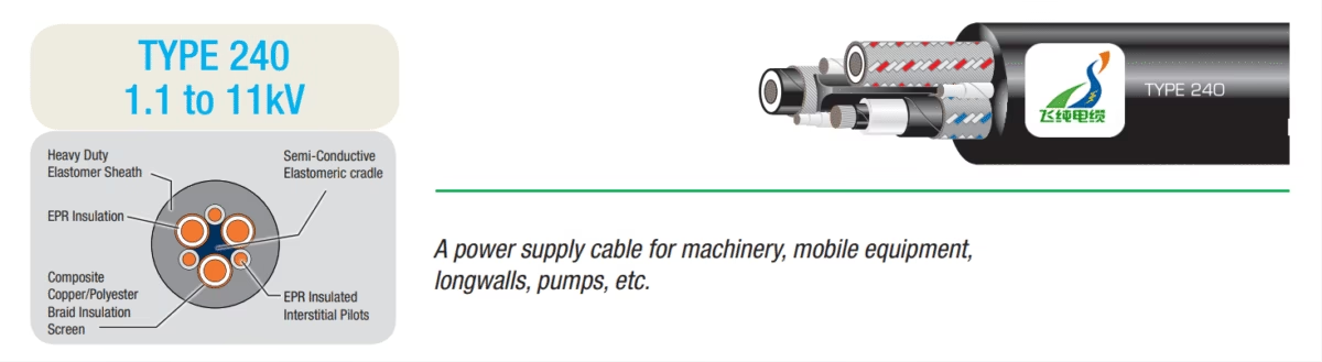
TYPE 240 1.1 to 11kV AS/NZS 1802:2003, AS/NZS 2802:2000 Australia Mining Cable: Comprehensive Technical Analysis
Executive Summary: The TYPE 240 mining cable represents a critical power distribution solution specifically engineered for underground coal mining environments in Australia and New Zealand. Manufactured in accordance with AS/NZS 1802:2003 and AS/NZS 2802:2000 standards, this EPR (Ethylene Propylene Rubber) insulated cable provides reliable power supply to machinery, mobile equipment, longwall systems, and pumping stations operating at voltage ratings from 1.1kV to 11kV. This comprehensive guide examines the technical specifications, material composition, safety standards, and comparative analysis with European VDE 0250-812 mining cable standards.
1. Introduction: Understanding TYPE 240 Mining Cables
1.1 Primary Applications
TYPE 240 cables serve as essential power supply conductors for critical mining equipment in underground coal mining operations. The cable’s robust construction and electrical characteristics make it particularly suitable for powering continuous miners, longwall shearer systems, hydraulic pump stations, shuttle cars, and various mobile mining machinery that operate in challenging underground environments. These cables must maintain reliable electrical performance while withstanding significant mechanical stress, exposure to moisture, and temperature variations encountered in subterranean mining operations.
1.2 Regulatory Framework
The TYPE 240 cable design adheres to multiple Australian and New Zealand standards that ensure safety and performance in underground coal mining applications:
According to industry documentation, AS/NZS 1802:2003 specifically addresses elastomer-insulated, elastomer-sheathed reeling and trailing electric cables for underground coal mine usage, with a fundamental requirement that cables used for alternating current supply demonstrate electrical symmetry to prevent ground fault hazards.
2. Technical Construction and Material Structure
2.1 Multi-Layer Architecture
The TYPE 240 cable features a sophisticated multi-layer construction designed to provide both electrical performance and mechanical durability. The engineering approach incorporates multiple protective and functional layers, each serving specific purposes in the overall cable performance profile.
2.2 Conductor System
At the core of the TYPE 240 cable lies a three-phase conductor system manufactured from flexible stranded tinned annealed copper. The tinning process provides enhanced corrosion resistance and improved solderability during termination procedures. The conductor sizing ranges from 6mm² to 150mm², accommodating various power transmission requirements across different mining applications. The flexible stranding pattern ensures the cable maintains necessary flexibility for mobile equipment applications while minimizing electrical resistance that would otherwise contribute to power losses and heat generation.
2.3 Insulation System: EPR Technology
The insulation material selection represents a critical design consideration for mining cable applications. TYPE 240 cables utilize EPR (Ethylene Propylene Rubber) insulation, a thermosetting elastomeric compound that exhibits superior electrical and mechanical properties compared to alternative insulation materials. Research indicates that EPR insulation demonstrates exceptional dielectric strength, maintaining breakdown voltage characteristics throughout the cable’s operational lifespan even in wet underground environments. The EPR compound formulation typically includes ethylene propylene rubber resin, mineral fillers, antioxidants, stabilizers, curing agents, and metal oxides carefully balanced to optimize electrical insulation properties, thermal stability, and environmental resistance.
EPR insulation offers several performance advantages critical to mining applications. The material maintains flexibility across a wide temperature range, typically from -40°C to 105°C for continuous operation, with emergency overload ratings reaching 140°C and short-circuit withstand capability up to 250°C. This thermal performance ensures reliable operation across the temperature variations encountered in underground mining environments. Additionally, EPR demonstrates superior resistance to water treeing phenomena compared to cross-linked polyethylene alternatives, providing enhanced long-term reliability in the moisture-rich conditions characteristic of underground coal mines.
2.4 Screening and Earthing Components
The TYPE 240 cable incorporates multiple screening layers that serve both electrical and safety functions. For cables rated 3.3kV and above, a semiconductive compound conductor screen surrounds each power conductor, ensuring uniform electric field distribution and preventing localized electrical stress concentrations. Individual insulation screens consisting of semiconductive elastomer material provide additional field control and facilitate safe cable termination procedures.
The overall core screen comprises semiconductive PCP (Polychloroprene) filling and covering that envelops the three-phase conductor assembly. Three interstitial earth conductors, constructed from flexible stranded tinned copper and covered with semiconductive PCP, are positioned between the power conductors. This arrangement creates a comprehensive protective earth contact system that immediately grounds any object penetrating the outer sheath before contact with energized power conductors occurs, representing a critical safety feature in mining environments where mechanical cable damage risks are elevated.
2.5 Pilot Conductor System
TYPE 240 cables incorporate interstitial pilot conductors that provide essential earth continuity monitoring and control circuit functionality. These pilot conductors, manufactured from flexible stranded tinned copper with EPR insulation, enable continuous monitoring of earthing system integrity throughout cable operation. The pilot sizing ranges from 1.06mm² to 16.92mm² depending on the main conductor size, providing adequate current carrying capacity for control and monitoring functions while maintaining cable flexibility.
2.6 Outer Sheath Protection
The heavy-duty elastomeric outer sheath represents the cable’s final line of defense against environmental and mechanical threats. This elastomer compound formulation provides resistance to abrasion, tearing, impact, chemical exposure, and environmental weathering. The sheath thickness varies from 3.8mm for smaller conductor sizes to 9.6mm for larger configurations, ensuring adequate mechanical protection proportional to cable size and expected mechanical stress levels. The elastomeric sheath maintains flexibility even at low temperatures, preventing cracking and splitting during cold weather operations or storage.
3. Complete Technical Specifications
3.1 TYPE 240.1 Series (1.1kV Voltage Rating)
| Part Number | Voltage | Conductor Size (mm²) | Conductor Dia. (mm) | Screen Area (mm²) | Pilot Size (mm²) | Cable Diameter (mm) | Weight (kg/100m) |
|---|---|---|---|---|---|---|---|
| MCU-240.1-006 | 1.1kV | 6 | 9.1 | 7.2 | 1.06 | 34.7 | 144 |
| MCU-240.1-010 | 1.1kV | 10 | 10.0 | 8.6 | 1.7 | 36.6 | 170 |
| MCU-240.1-016 | 1.1kV | 16 | 11.3 | 9.6 | 2.76 | 39.8 | 211 |
| MCU-240.1-025 | 1.1kV | 25 | 12.6 | 11.3 | 4.45 | 43.2 | 269 |
| MCU-240.1-035 | 1.1kV | 35 | 13.8 | 12.4 | 6.15 | 46.5 | 328 |
| MCU-240.1-050 | 1.1kV | 50 | 15.5 | 14.4 | 8.06 | 51.0 | 414 |
| MCU-240.1-070 | 1.1kV | 70 | 17.4 | 16.5 | 12.69 | 55.9 | 527 |
| MCU-240.1-095 | 1.1kV | 95 | 19.6 | 18.2 | 12.69 | 61.9 | 657 |
| MCU-240.1-120 | 1.1kV | 120 | 21.5 | 20.3 | 13.75 | 66.7 | 783 |
| MCU-240.1-150 | 1.1kV | 150 | 23.6 | 22.3 | 16.92 | 72.2 | 938 |
3.2 TYPE 240.3 Series (3.3kV Voltage Rating)
| Part Number | Voltage | Conductor Size (mm²) | Conductor Dia. (mm) | Screen Area (mm²) | Pilot Size (mm²) | Cable Diameter (mm) | Weight (kg/100m) |
|---|---|---|---|---|---|---|---|
| MCU-240.3-016 | 3.3kV | 16 | 13.7 | 13.4 | 2.76 | 55.7 | 351 |
| MCU-240.3-025 | 3.3kV | 25 | 15.0 | 14.8 | 4.45 | 59.2 | 418 |
| MCU-240.3-035 | 3.3kV | 35 | 16.2 | 16.1 | 6.15 | 62.4 | 486 |
| MCU-240.3-050 | 3.3kV | 50 | 17.8 | 17.5 | 8.06 | 66.5 | 580 |
| MCU-240.3-070 | 3.3kV | 70 | 19.4 | 19.6 | 12.69 | 70.7 | 697 |
| MCU-240.3-095 | 3.3kV | 95 | 21.2 | 20.6 | 12.69 | 75.7 | 826 |
| MCU-240.3-120 | 3.3kV | 120 | 22.8 | 27.2 | 13.75 | 80.7 | 969 |
| MCU-240.3-150 | 3.3kV | 150 | 24.5 | 39.6 | 16.92 | 85.2 | 1149 |
3.3 TYPE 240.6 Series (6.6kV Voltage Rating)
| Part Number | Voltage | Conductor Size (mm²) | Conductor Dia. (mm) | Screen Area (mm²) | Pilot Size (mm²) | Cable Diameter (mm) | Weight (kg/100m) |
|---|---|---|---|---|---|---|---|
| MCU-240.6-016 | 6.6kV | 16 | 17.7 | 16.3 | 2.76 | 66.6 | 490 |
| MCU-240.6-025 | 6.6kV | 25 | 19.0 | 18.3 | 4.45 | 70.1 | 566 |
| MCU-240.6-035 | 6.6kV | 35 | 20.2 | 20.3 | 6.15 | 73.3 | 646 |
| MCU-240.6-050 | 6.6kV | 50 | 21.8 | 20.3 | 8.06 | 77.2 | 741 |
| MCU-240.6-070 | 6.6kV | 70 | 23.4 | 22.6 | 12.69 | 81.6 | 873 |
| MCU-240.6-095 | 6.6kV | 95 | 25.2 | 29.6 | 12.69 | 87.4 | 1030 |
| MCU-240.6-120 | 6.6kV | 120 | 26.8 | 32.3 | 13.75 | 91.7 | 1173 |
| MCU-240.6-150 | 6.6kV | 150 | 28.5 | 47.3 | 16.92 | 98.1 | 1381 |
3.4 TYPE 240.11 Series (11kV Voltage Rating)
| Part Number | Voltage | Conductor Size (mm²) | Conductor Dia. (mm) | Screen Area (mm²) | Pilot Size (mm²) | Cable Diameter (mm) | Weight (kg/100m) |
|---|---|---|---|---|---|---|---|
| MCU-240.11-025 | 11kV | 25 | 24.2 | 24.3 | 4.45 | 84.3 | 805 |
| MCU-240.11-035 | 11kV | 35 | 25.4 | 30.3 | 6.15 | 88.5 | 909 |
| MCU-240.11-050 | 11kV | 50 | 27.0 | 32.3 | 8.06 | 92.4 | 1022 |
| MCU-240.11-070 | 11kV | 70 | 28.6 | 34.3 | 12.69 | 96.8 | 1168 |
| MCU-240.11-095 | 11kV | 95 | 30.4 | 48.3 | 12.69 | 103.7 | 1371 |
4. Comparison: AS/NZS 1802:2003 TYPE 240 vs. VDE 0250-812 Mining Cables
4.1 Standards Overview
While the Australian AS/NZS 1802:2003 standard governs TYPE 240 mining cables for underground coal mining applications, the German VDE 0250-812 standard represents an alternative regulatory framework widely recognized in European and international mining operations. Understanding the distinctions between these standards provides valuable context for cable selection in multinational mining operations or equipment procurement decisions.
4.2 Voltage Rating Comparison
| Parameter | AS/NZS 1802:2003 TYPE 240 | VDE 0250-812 |
|---|---|---|
| Voltage Rating | 1.1kV to 11kV | Up to 450/750V (Part 812) Higher voltages in Parts 813-814 |
| Primary Application | Underground coal mining – power supply to machinery, longwalls, pumps | General mining and industrial applications – fixed installation and mobile equipment |
| Insulation Material | EPR (Ethylene Propylene Rubber) Type 3GI3 | EPR/EPDM per DIN VDE 0207 Part 21 |
| Sheath Material | Heavy-duty elastomer compound | EPR or polychloroprene elastomer per DIN VDE 0207 |
| Temperature Range | -40°C to +105°C (continuous) +140°C (emergency) +250°C (short circuit) | -25°C to +90°C (continuous) -40°C (fixed installation minimum) |
| Conductor Material | Flexible stranded tinned copper | Flexible stranded tinned copper |
| Screening System | Semiconductive screens + composite copper/polyester braid + interstitial earth conductors | Semiconductive layers (Parts 813-814) Maximum resistivity ≤200 Ω·m |
| Mechanical Protection | Heavy-duty elastomer sheath with enhanced abrasion resistance | High resistance to ripping, notching, abrasion, oils, chemicals |
| Electrical Symmetry | Mandatory requirement for AC supply cables | Design-dependent based on application |
4.3 Key Differences Analysis
The fundamental distinction between AS/NZS 1802:2003 TYPE 240 cables and VDE 0250-812 specified cables lies in their voltage rating scope and application specificity. TYPE 240 cables address medium voltage requirements ranging from 1.1kV to 11kV, making them suitable for primary power distribution in extensive underground mining operations. VDE 0250 Part 812 primarily addresses lower voltage applications up to 450/750V, with higher voltage requirements covered under Parts 813 and 814 of the VDE 0250 series.
Temperature performance specifications reveal another significant differentiation. TYPE 240 cables exhibit superior continuous operating temperature capability at 105°C compared to the 90°C rating typical of VDE 0250-812 cables. This enhanced thermal performance becomes particularly advantageous in applications involving high ambient temperatures or elevated electrical loading conditions. The emergency overload rating of 140°C for TYPE 240 cables provides additional operational margin during temporary fault conditions or peak demand periods.
Both standards mandate EPR insulation technology, recognizing its superior performance characteristics for mining applications. However, the AS/NZS 1802:2003 standard includes a specific requirement for electrical symmetry in alternating current supply cables. This symmetry requirement ensures balanced impedance characteristics across all three phases, minimizing potential ground fault currents and enhancing personnel safety in underground environments where touch potential hazards represent significant risks.
5. Electrical Characteristics and Performance Parameters
5.1 Current Carrying Capacity
The current carrying capacity of TYPE 240 cables depends on multiple variables including conductor size, voltage rating, installation method, ambient temperature, and grouping factors. As a general principle, current ratings must account for the thermal dissipation characteristics of the installation environment. Underground mining installations typically experience restricted ventilation and elevated ambient temperatures compared to surface installations, necessitating conservative derating factors in ampacity calculations.
For reference purposes, a 35mm² conductor at 1.1kV rating operating at 30°C ambient temperature with 90°C conductor temperature might carry approximately 120-140 amperes in free air installation. However, actual operating conditions in underground mines may require derating to 70-80% of this theoretical maximum due to restricted cooling, cable grouping effects, and elevated ambient temperatures. Professional electrical engineering consultation should always precede final cable sizing decisions to ensure compliance with local electrical codes and mine safety regulations.
5.2 Voltage Drop Considerations
Voltage drop represents a critical design consideration in mining cable installations, particularly for extended cable runs to remote mining equipment. Excessive voltage drop results in reduced equipment performance, motor overheating, and potential protection system malfunctions. The voltage drop calculation must account for conductor resistance at operating temperature, inductive reactance, and load power factor characteristics.
For copper conductors at 75°C operating temperature, the resistivity approximately equals 0.0217 Ω·mm²/m. A 50mm² conductor supplying 100 amperes over a 500-meter cable run would experience a resistive voltage drop of approximately 21.7 volts per phase, representing 1.97% voltage drop at 1.1kV nominal voltage. While this remains within typical acceptable limits of 2-3% for branch circuits, longer runs or higher currents may require conductor upsizing to maintain adequate voltage regulation.
5.3 Insulation Resistance and Dielectric Strength
EPR insulation in TYPE 240 cables maintains high insulation resistance values throughout the cable’s operational lifetime. Minimum insulation resistance requirements typically specify values exceeding 100 MΩ·km at 20°C for new cables, although this value decreases with temperature according to the relationship that insulation resistance approximately halves for every 10°C temperature increase. Regular insulation resistance testing during preventive maintenance programs helps identify insulation degradation before complete failure occurs.
Dielectric strength testing verifies the insulation’s ability to withstand electrical stress without breakdown. EPR insulated cables typically withstand test voltages of 3.5 to 4 times the rated voltage for specified test durations without insulation failure. Research conducted over multi-decade periods has demonstrated that EPR insulation maintains breakdown strength characteristics even after extended exposure to wet underground environments and normal operational electrical stress, contrasting favorably with certain cross-linked polyethylene formulations that may experience degradation in impulse strength under similar conditions.
6. Safety Standards and Operational Thresholds
6.1 Earth Continuity Monitoring
The interstitial pilot conductors incorporated in TYPE 240 cables enable continuous earth continuity monitoring, a critical safety function in underground mining operations. These pilot conductors connect to specialized monitoring systems that detect earth conductor degradation, interruption, or excessive resistance conditions. Upon detection of earth system anomalies, automated protection systems can initiate equipment shutdown sequences, preventing continued operation with compromised protective earthing that could expose personnel to electrocution hazards.
6.2 Fault Current Withstand Capability
Mining cables must withstand substantial fault current levels during short circuit conditions without sustaining permanent damage that could compromise subsequent operation. The short circuit temperature rating of 250°C for TYPE 240 cables ensures the insulation and conductor materials can tolerate brief fault current exposure without thermal degradation. Fault current calculations must consider the available short circuit capacity at the power source, impedance characteristics of the supply system and cable, and protective device operating characteristics to verify that fault clearance occurs before thermal damage thresholds are exceeded.
⚠ Critical Safety Thresholds
- Maximum Continuous Operating Temperature: 105°C at conductor
- Emergency Overload Temperature: 140°C (limited duration)
- Short Circuit Temperature: 250°C (maximum 5 seconds)
- Minimum Bending Radius: Typically 12-15 times cable diameter during installation, 20 times diameter for reeling applications
- Minimum Installation Temperature: -5°C (cable must be warmed before installation at lower temperatures)
- Insulation Resistance: Minimum 100 MΩ·km at 20°C for acceptance testing
6.3 Mechanical Stress Limitations
TYPE 240 cables must endure substantial mechanical stresses during both installation and operation. Tensile stress during cable pulling operations should not exceed 50 N/mm² of conductor cross-sectional area to prevent permanent conductor elongation or insulation damage. Dynamic bending during reeling and unreeling cycles on mobile equipment necessitates generous bending radius allowances. The cable construction incorporates elastomeric materials specifically selected for their resistance to flexing fatigue, enabling thousands of bending cycles without structural degradation.
7. Installation Precautions and Best Practices
7.1 Pre-Installation Inspection
Prior to installation, comprehensive cable inspection procedures verify that manufacturing quality standards have been maintained and that no damage occurred during transportation or storage. Visual examination should confirm sheath integrity with no visible cuts, abrasions, or deformations. Cable drums should be inspected for damage that might have transmitted mechanical stress to the cable. Electrical testing including insulation resistance measurement and continuity verification of all conductors and earth screens ensures electrical integrity before installation proceeds.
7.2 Cable Handling and Storage
Proper cable storage prevents degradation prior to installation. Cable drums should be stored on firm, level surfaces in covered locations protected from direct sunlight, precipitation, and temperature extremes. The elastomeric sheath materials can experience accelerated aging when exposed to ultraviolet radiation or ozone, particularly at elevated temperatures. Storage temperature should remain within the range of -25°C to +50°C to prevent insulation hardening or compound migration issues.
During handling operations, cable should never be dragged across rough surfaces that could abrade or cut the outer sheath. Lifting equipment must distribute load forces to prevent excessive local stress concentrations. Small diameter cables may be manually handled, while larger sizes require mechanical lifting equipment. Under no circumstances should cable be lifted by the conductors protruding from cable ends, as this concentrates excessive stress at the termination point.
7.3 Installation Environmental Conditions
Cable installation should not proceed when ambient temperatures fall below -5°C, as the elastomeric materials become less flexible at low temperatures, increasing the risk of sheath cracking during bending. If installation in cold conditions cannot be avoided, the cable should be stored in a heated environment for at least 24 hours prior to installation, and installation should proceed as rapidly as possible to minimize cold exposure time.
Underground mining environments present unique installation challenges including restricted working space, wet conditions, and uneven support surfaces. Cable support systems must be designed to prevent excessive tensile stress on supported cable sections while allowing for thermal expansion and contraction. Support spacing typically ranges from 0.5 to 1.0 meters depending on cable size, orientation, and mechanical stress expectations.
7.4 Termination and Jointing Procedures
Cable termination represents a critical interface between the cable and connected equipment. Proper termination procedures ensure electrical continuity, maintain insulation integrity, and provide mechanical strain relief. Semiconductive screening layers must be carefully removed and dressed to prevent electrical stress concentrations at the termination boundary. Insulation stripping must be performed with tools specifically designed for EPR materials to prevent nicking or scoring that could initiate electrical treeing under operational voltage stress.
All terminations must incorporate earth continuity connections to both the interstitial earth conductors and cable screen systems. The pilot conductor terminations require secure, low-resistance connections to enable reliable earth monitoring system operation. Termination components including cable glands, termination lugs, and heat-shrink sealing systems must be rated for the cable voltage, current, and environmental conditions encountered in the specific application.
8. Common Problems and Troubleshooting
8.1 Insulation Degradation
Progressive insulation degradation represents the primary long-term failure mechanism for mining cables. While EPR insulation demonstrates superior resistance to water treeing compared to certain polyethylene formulations, chemical contamination or thermal overload conditions can still compromise insulation integrity. Regular insulation resistance testing performed during scheduled maintenance shutdowns enables trending analysis to identify cables experiencing abnormal degradation rates before complete failure occurs.
Factors accelerating insulation degradation include sustained overcurrent operation leading to elevated conductor temperatures, exposure to aggressive chemicals not anticipated in the original cable specification, and mechanical damage to outer protective layers allowing moisture ingress to insulation systems. Preventive measures include proper cable sizing to avoid thermal overload, chemical compatibility verification for specific environmental exposures, and regular visual inspection to identify mechanical damage requiring prompt remedial action.
8.2 Conductor Damage and Breakage
Conductor strand breakage typically results from excessive mechanical flexing, particularly in reeling cable applications where repeated bending and straightening cycles induce flexing fatigue. While the stranded conductor construction provides redundancy allowing continued operation with some strand breakage, progressive conductor damage eventually leads to localized heating at points of reduced conductor cross-section, potentially initiating insulation thermal degradation.
Conductor damage detection relies primarily on increased circuit resistance measurements compared to baseline values established during commissioning. A resistance increase exceeding 10% of the original value warrants detailed investigation. Thermographic inspection during loaded operation can identify localized heating indicative of conductor damage. Cables experiencing significant conductor damage should be replaced rather than repaired, as conductor splice repairs introduce additional resistance and potential failure points.
8.3 Mechanical Damage to Outer Sheath
External mechanical damage represents the most common immediate cable failure mechanism in mining environments. Impact from mobile equipment, crushing between moving machinery components, and abrasion against sharp rock surfaces all contribute to sheath damage risks. While minor surface abrasion may not immediately compromise cable operation, progressive wear eventually breaches the sheath, allowing moisture ingress and exposure of internal components to mechanical damage.
Damaged cable sections require prompt attention to prevent progression to complete cable failure. Minor sheath damage affecting only the outer surface without penetrating to internal layers may be temporarily repaired using elastomeric repair compounds or heat-shrink repair sleeves. However, damage penetrating to conductor or insulation layers necessitates cable replacement or formal splicing procedures using qualified cable jointing components.
8.4 Earth Continuity System Failures
Earth continuity monitoring system malfunctions can result from pilot conductor damage, connection failures at termination points, or monitoring system equipment faults. Troubleshooting procedures should systematically verify pilot conductor continuity, termination connection integrity, and monitoring system functionality. False indications of earth system failure can disrupt mining operations unnecessarily, making accurate fault diagnosis essential for maintaining productivity.
9. Maintenance and Testing Protocols
9.1 Routine Visual Inspection
Regular visual inspection represents the first line of defense against cable system failures. Inspection frequency should align with equipment usage intensity and environmental exposure severity, typically ranging from weekly examinations for frequently relocated equipment to monthly inspections for relatively stationary installations. Visual examination should identify sheath damage, abnormal wear patterns, cable support system degradation, termination loosening, and environmental contamination accumulation.
9.2 Electrical Testing Program
Comprehensive electrical testing programs incorporate multiple test types performed at intervals determined by cable age, usage intensity, and historical performance. Insulation resistance testing conducted at regular intervals establishes trending data enabling prediction of insulation degradation progression. Tests should be performed at consistent temperatures to enable meaningful comparison, with results corrected to a standard reference temperature of 20°C.
Conductor resistance measurements verify conductor integrity and identify strand breakage or connection degradation. Comparison against baseline measurements established during cable commissioning enables quantitative assessment of conductor condition. Resistance values exceeding 110% of the baseline measurement warrant detailed investigation.
Earth continuity verification ensures protective earth systems maintain low resistance paths essential for personnel safety. Resistance values should not exceed equipment manufacturer specifications, typically in the range of 0.1 to 1.0 ohms depending on system design and cable length.
9.3 Documentation and Record Keeping
Comprehensive documentation of cable installations, maintenance activities, and test results provides essential information for condition assessment and replacement planning. Records should include cable specifications, installation date, test results with trending analysis, maintenance activities performed, and any observed anomalies or repairs. This historical data enables informed decisions regarding cable replacement timing and contributes to continuous improvement of cable selection and installation practices.
10. Conclusion
TYPE 240 mining cables manufactured in accordance with AS/NZS 1802:2003 and AS/NZS 2802:2000 standards represent sophisticated electrical components engineered specifically for the demanding requirements of underground coal mining operations. The multi-layer construction incorporating EPR insulation, comprehensive screening systems, interstitial earth conductors, and heavy-duty elastomeric sheathing provides the electrical performance, mechanical durability, and safety features essential for reliable power distribution in challenging mining environments.
Successful cable system performance requires attention to proper cable selection, installation procedures, operational practices, and maintenance protocols. The comparative analysis with VDE 0250-812 European mining cable standards illustrates both commonalities and distinctions between international approaches to mining cable design, providing valuable perspective for multinational mining operations and equipment procurement decisions.
As mining operations continue to evolve with increasing automation, deeper extraction depths, and more demanding environmental conditions, cable technology must advance correspondingly. TYPE 240 cables incorporate proven materials and construction techniques while remaining adaptable to emerging requirements through ongoing materials development and design optimization. Proper understanding and application of these cable systems contributes significantly to safe, efficient, and reliable mining operations.
Industry Resources and Technical Support
For additional information on specialized cable applications and technical specifications:
Reeling Cable Solutions and Applications | Crane Cable Systems and TechnologiesContact Anhui Feichun Special Cable Co., Ltd.
For technical consultations, product specifications, and custom cable solutions:
安徽飞纯特种电缆有限公司 – Professional Mining Cable Solutions


