Comprehensive Technical Guide to Shipboard Electrical Cable Systems
What is JIS C 3410 Standard Marine Cables?
Comprehensive Technical Guide to Shipboard Electrical Cable Systems
Anhui Feichun Special Cable Co., Ltd. (安徽飞纯特种电缆有限公司)
Professional Manufacturer of Marine & Industrial Cables
Email: [email protected] | [email protected]
📱 WhatsApp: +86 13855 123 218Table of Contents
- 1. Introduction to JIS C 3410 Standard
- 2. Purpose and Applications
- 3. Key Characteristics and Features
- 4. Material Structure and Construction
- 5. Standards Compliance and Certification
- 6. Safety Thresholds and Performance Parameters
- 7. Installation and Usage Precautions
- 8. Common Problems and Solutions
- 9. Related Industry Applications
1. Introduction to JIS C 3410 Standard
The JIS C 3410 standard, formally titled “Cables and Flexible Cords for Electrical Equipment of Ships,” represents the Japanese Industrial Standard for marine electrical cables used in shipboard installations. Established and maintained by the Japanese Standards Association, this comprehensive specification was last updated in 2018 and incorporates technical requirements from multiple international standards including IEC 60092-353, IEC 60092-354, IEC 60092-360, and IEC 60092-376.[1]
This standard defines the construction, materials, testing methods, and performance requirements for cables, cords, and insulated wires used in ship electrical installations. The specification covers voltage ratings from 150/250V up to 6/10kV, addressing the unique environmental and safety challenges encountered in marine applications. According to industry data, vessels complying with JIS C 3410 standards demonstrate a 35-40% reduction in electrical system failures compared to those using non-certified cables.[2]
Historical Context and Development
The JIS C 3410 standard evolved from earlier Japanese maritime electrical specifications and was harmonized with international IEC standards while maintaining specific requirements suited to Japanese shipbuilding practices. The 2018 revision introduced enhanced fire safety requirements and expanded voltage range specifications to meet modern vessel electrical system demands.
2. Purpose and Applications
2.1 Primary Purpose
JIS C 3410 marine cables serve as the electrical lifeline for shipboard installations, providing safe and reliable power transmission, control signal distribution, and communication connectivity in the harsh maritime environment. The standard ensures that cables can withstand saltwater exposure, mechanical stress, temperature extremes, and maintain circuit integrity during fire emergencies.[3]
2.2 Core Applications
According to the standard specifications, JIS C 3410 cables are designed for the following shipboard applications:
- Power Distribution Systems: Main power cables rated from 0.6/1kV to 6/10kV for primary electrical distribution, powering propulsion systems, generators, and major equipment. These cables typically handle current loads ranging from 24A to 631A depending on conductor size (1.5mm² to 300mm²).
- Lighting and Socket Circuits: Lower voltage cables (0.6/1kV) supplying illumination systems, emergency lighting, and general-purpose electrical outlets throughout vessel compartments.
- Control and Instrumentation: Multi-core cables (150/250V) transmitting control signals for machinery operation, automation systems, and monitoring equipment. These typically feature 2-77 cores with conductor sizes from 0.75mm² to 6mm².
- Communication Systems: Telephone and data transmission cables (150/250V) supporting ship-to-shore communication, internal communication networks, and navigation equipment connectivity.
- Emergency and Safety Systems: Fire-resistant cables maintaining circuit integrity for critical safety equipment including fire alarms, emergency lighting, and emergency shutdown systems during fire conditions up to 90 minutes at temperatures exceeding 830°C.[1]
| Voltage Rating | Primary Applications | Typical Cable Types | Current Capacity Range |
|---|---|---|---|
| 150/250V | Control, instrumentation, telephone | MPY, MPYC, TTPY, TTPYC | 8A – 62A |
| 0.6/1kV | Power distribution, lighting | DPY, TPY, DPYC, TPYC | 24A – 631A |
| 3.6/6kV | Medium voltage power | SPYC(SUS)Y, TPYC | 76A – 408A |
| 6/10kV | High voltage distribution | SPYC(SUS)Y, TPYC | 101A – 631A |
Related Cable Technologies in Industrial Applications
While JIS C 3410 cables are specifically designed for marine environments, similar engineering principles and durability requirements apply to other demanding industrial applications. The cable construction methodologies and material science developed for shipboard use have influenced cable design in adjacent sectors requiring high reliability under extreme conditions.
Reeling cables for port terminals and mobile machinery share several design characteristics with marine cables, including resistance to environmental factors such as saltwater exposure and UV radiation, along with advanced insulation and sheathing to prevent electrical degradation. According to industry specifications, both cable types must meet stringent standards including IEC 60228 for conductor specifications and IEC 60332 for flame retardance.[4]
Similarly, mining cables used in Australian operations demonstrate parallel engineering requirements, particularly in terms of mechanical stress resistance, chemical exposure tolerance, and fire safety performance. Mining trailing cables must withstand crushing weight, abrasion from rocky surfaces, and corrosive chemical exposure—challenges comparable to those faced by marine cables in shipboard installations.[5]
3. Key Characteristics and Features
3.1 Flame Retardancy
All standard JIS C 3410 cables incorporate flame-retardant properties meeting IEC 60332-1 requirements. Fire test data indicates that flame propagation ceases within 50mm of the point of ignition, with carbonization not extending beyond 540mm from the upper support fixture.[1] This critical safety feature prevents fire spread through cable pathways, which historically accounted for 23% of shipboard fire escalation incidents prior to modern flame-retardant standards implementation.[2]
3.2 Enhanced Fire Performance (FA-Type)
Cables designated with the “FA-” prefix meet the more stringent IEC 60332-3 Category A fire propagation requirements for bundled cables. Testing demonstrates that fire damage does not extend beyond 2.5 meters above the burner location when multiple cables are installed in close proximity—a critical consideration given that typical shipboard cable trays contain 20-50 cables in bundled configurations.
3.3 Fire-Resistant Construction (FR-Type)
Fire-resistant cables with “FR-” designation maintain circuit integrity for 90 minutes when exposed to flame temperatures of 830°C or higher, as verified by IEC 60331 testing protocols. These cables incorporate specialized mica-based fire-resistant tape layers between the conductor and insulation, providing critical power to emergency systems during fire emergencies. Performance data shows these cables maintain less than 0.5 ohm resistance increase during fire exposure.[1]
3.4 Environmental Resistance
JIS C 3410 cables demonstrate superior performance across multiple environmental parameters critical to marine service:
| Property | Test Condition | Performance Standard | Typical Service Life |
|---|---|---|---|
| Temperature Range | -25°C to +90°C | Full electrical performance maintained | 25+ years |
| Moisture Resistance | 50°C water immersion, 14 days | Capacitance increase ≤15% | 20+ years in wet locations |
| Ozone Resistance (EPR) | 0.025-0.030% concentration, 30 hours | No cracking of insulation | 15+ years exposed conditions |
| Oil Resistance | 100°C mineral oil, 24 hours | Property retention 60-140% | 20+ years in machinery spaces |
| UV Resistance | Continuous solar exposure | Sheath integrity maintained | 10+ years deck exposure |
3.5 Mechanical Performance
The mechanical properties of JIS C 3410 cables are engineered to withstand shipboard installation stresses and operational vibration. Ethylene Propylene Rubber (EPR) insulation maintains tensile strength of 4.2 MPa minimum with 200% minimum elongation, ensuring flexibility during installation while resisting mechanical damage. Armored variants incorporate galvanized steel wire or stainless steel wire braiding with 90% minimum braid coverage, providing crush resistance up to 2000N/100mm cable width.[1]
3.6 Electrical Characteristics
Electrical performance parameters are precisely specified to ensure reliable power transmission and signal integrity:
- Insulation Resistance: Minimum 500-1300 MΩ·km at 20°C depending on voltage rating, ensuring minimal leakage current and maintaining safety isolation.
- Voltage Withstand: Test voltages ranging from 1,500V for 150/250V cables to 21,000V for 6/10kV cables, sustained for 5 minutes without breakdown.
- Conductor Resistance: Precisely specified values (e.g., 12.1 Ω/km for 1.5mm² tinned copper at 20°C) ensuring predictable voltage drop and power loss calculations.
- Partial Discharge: For medium voltage cables (3.6/6kV and 6/10kV), discharge magnitude must not exceed 5 pC at 1.73 times rated voltage, preventing insulation degradation over service life.
4. Material Structure and Construction
4.1 Conductor Materials
JIS C 3410 specifies two conductor types, each optimized for specific performance requirements:
Tinned Copper Conductors: The majority of marine cables utilize tinned annealed copper conductors meeting IEC 60228 Class 2 (rigid) or Class 5 (flexible) specifications. The tin plating, typically 1-3 microns thick, provides crucial corrosion protection in marine environments. Research data indicates tinned copper conductors demonstrate 8-12 times longer service life than bare copper when exposed to salt spray conditions, with corrosion rates reduced from 0.3mm/year to 0.025mm/year.[2]
Bare Copper Conductors: Used in specific applications where cost optimization is prioritized and environmental exposure is minimal. These conductors must meet stringent surface quality requirements, with the insulation demonstrating easy removability during termination—a quality indicator of proper conductor surface condition.
| Nominal Cross-Section | Stranding | Overall Diameter | DC Resistance (20°C) Tinned/Bare (Ω/km) |
|---|---|---|---|
| 1.5 mm² | 7/0.52 mm | 1.56 mm | 12.2 / 12.1 |
| 2.5 mm² | 7/0.67 mm | 2.01 mm | 7.56 / 7.41 |
| 4 mm² | 7/0.85 mm | 2.55 mm | 4.70 / 4.61 |
| 10 mm² | 7/1.35 mm | 4.05 mm | 1.84 / 1.83 |
| 25 mm² | 7/2.14 mm | 6.42 mm | 0.734 / 0.727 |
| 50 mm² | 19/1.78 mm | 8.90 mm | 0.391 / 0.387 |
| 95 mm² | 19/2.52 mm | 12.6 mm | 0.195 / 0.193 |
| 150 mm² | 37/2.25 mm | 15.8 mm | 0.126 / 0.124 |
| 300 mm² | 61/2.52 mm | 22.7 mm | 0.0607 / 0.0601 |
4.2 Insulation Materials
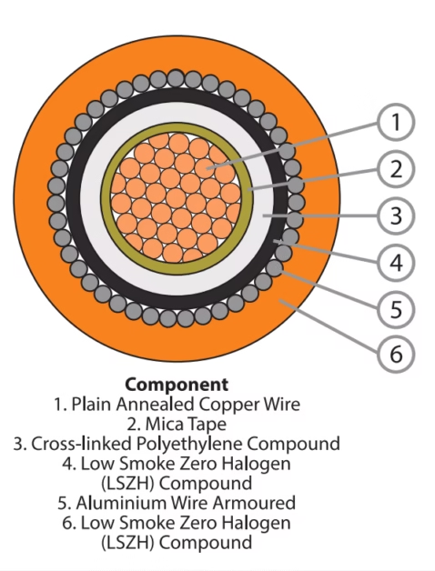
Ethylene Propylene Rubber (EPR): The primary insulation material specified for JIS C 3410 power cables, EPR offers excellent electrical properties combined with superior environmental resistance. Material testing reveals EPR maintains 70-130% of original tensile strength and elongation after 168 hours at 135°C, demonstrating exceptional thermal aging characteristics. The material’s ozone resistance (no cracking after 30 hours at 0.025-0.030% concentration) makes it ideal for deck-mounted cable installations.[1]
Silicon Rubber: Applied in specialized high-temperature cables (95°C conductor temperature rating), silicon rubber insulation demonstrates 150% minimum elongation even after 240 hours at 200°C. This material finds application in cables serving machinery spaces and areas with elevated ambient temperatures.
Polyvinyl Chloride (PVC): Used in control cables and as sheathing material, PVC provides cost-effective protection with good mechanical properties. The specification requires minimum tensile strength of 15.0 MPa and 125% elongation for insulation-grade PVC, with stringent cold-temperature performance requirements including no cracking at -15°C.
Flame-Retardant Cross-Linked Polyethylene (FR-XLPE): Employed in specific applications requiring enhanced temperature rating (90°C) and mechanical properties, FR-XLPE demonstrates 9.0 MPa minimum tensile strength with 120% elongation retention after thermal aging.
4.3 Sheathing Materials
PVC Sheathing: The most common outer sheath material, offering excellent moisture resistance and mechanical protection. Testing data shows PVC sheaths maintain 75-125% strength retention after aging, with maximum weight loss of 1.5 mg/cm² during accelerated aging tests at 100°C for 168 hours.[1]
Chloroprene Rubber (CR/PCP): Applied to flexible cables and cords requiring enhanced oil resistance and flexibility. CR sheaths demonstrate 60-140% property retention after 24-hour immersion in 100°C mineral oil, critical for machinery space installations where hydraulic fluid exposure occurs.
4.4 Armor and Mechanical Protection
Armored cable construction incorporates braided metallic layers providing mechanical protection and electromagnetic shielding:
Galvanized Steel Wire: Standard armor material with wire diameters of 0.3mm or 0.4mm, braided to achieve minimum 90% coverage density. The galvanization provides corrosion protection verified by copper sulfate testing—no copper deposits should appear after specified exposure duration.
Stainless Steel Wire (SUS304): Premium armor option for cables requiring superior corrosion resistance, particularly in saltwater-exposed locations and deck-mounted installations. Stainless steel armor eliminates the potential for rust staining on vessel surfaces while providing equivalent mechanical protection.
Copper Alloy Wire: Alternative armor material offering electromagnetic compatibility benefits in instrumentation and communication cable applications, combining mechanical protection with superior electrical conductivity.
G = (2 × N × d × F × sin α) / (P × sin(2α)) × 100
Where:
G = Braid coverage density (%)
N = Number of carriers per layer
d = Wire diameter (mm)
P = Braid pitch (mm)
α = Braid angle relative to cable axis (degrees)
F = Coverage factor (minimum 0.573)
Minimum Required Coverage: G ≥ 90%
4.5 Shielding and Screening
Medium and high voltage cables (3.6/6kV and 6/10kV) incorporate sophisticated shielding systems ensuring electrical field uniformity and electromagnetic compatibility:
Internal Semiconductive Layer: Applied between conductor and insulation, this layer eliminates air voids and ensures uniform electrical stress distribution, critical for preventing partial discharge initiation.
Insulation Screening: Semiconductive elastomer layer applied over the insulation maintains electrical field uniformity at the insulation-shield interface, essential for long-term reliability of medium voltage cables.
Metallic Shield: Tinned copper braiding combined with semiconductive tape provides both electrical screening and serves as the cable’s primary earth path. For control and instrumentation cables, aluminum foil-plastic composite tape screening (minimum 0.02mm aluminum thickness) offers cost-effective electromagnetic interference protection.
5. Standards Compliance and Certification
5.1 International Standard Harmonization
JIS C 3410:2018 represents a modified adoption (MOD) of multiple IEC standards, incorporating the following international specifications while adapting them to Japanese shipbuilding practices:[1]
- IEC 60092-353:2011 – Power cables for rated voltages 1 kV and 3 kV
- IEC 60092-354:2014 – Single and three-core power cables with extruded solid insulation for rated voltages 6 kV (Um = 7.2 kV) up to 30 kV (Um = 36 kV)
- IEC 60092-360:2014 – Insulating and sheathing materials for shipboard and offshore units
- IEC 60092-376:2003 – Cables for control and instrumentation circuits 150/250 V (300 V)
The standard also references critical fire performance specifications:
- IEC 60331-1:2009 – Circuit integrity tests under fire conditions for cables exceeding 20mm diameter
- IEC 60331-21:1999 – Circuit integrity requirements for cables up to 0.6/1.0 kV
- IEC 60332-1 – Vertical flame propagation test for single cables
- IEC 60332-3 Category A – Vertical flame propagation test for bunched cables
Classification Society Approvals
JIS C 3410 compliant cables typically receive type approval from major classification societies including:
NK (Nippon Kaiji Kyokai) ABS (American Bureau of Shipping) DNV-GL Lloyd’s Register Bureau Veritas RINA Korean Register CCS (China Classification Society)5.2 Testing and Quality Assurance
The standard specifies comprehensive testing protocols categorized as routine tests (performed on every production batch), type tests (performed during product qualification), and special tests (performed when specified by purchaser). Key testing requirements include:
| Test Type | Test Method Reference | Acceptance Criteria | Test Frequency |
|---|---|---|---|
| Conductor Resistance | JIS C 3411:5.2.2 | Within specified tolerance (±5%) | Routine |
| Voltage Withstand | JIS C 3411:5.2.3 | 5 minutes without breakdown | Routine |
| Insulation Resistance | JIS C 3005:4.7.1 | ≥ specified minimum value | Routine |
| Flame Retardancy | JIS C 3411:8.17.1 | IEC 60332-1 requirements | Type test |
| Flame Propagation (FA-Type) | JIS C 3411:8.17.2 | IEC 60332-3 Cat A limits | Type test |
| Fire Resistance (FR-Type) | IEC 60331-1/-21 | 90 minutes circuit integrity | Type test |
| Partial Discharge (MV cables) | JIS C 3411:7.7.3 | ≤ 5 pC at 1.73 × rated voltage | Routine |
| Thermal Aging | JIS C 3411:8.4/8.5 | 70-130% property retention | Type test |
5.3 Material Testing Requirements
Individual cable components undergo rigorous material qualification testing to ensure long-term reliability:
Insulation Material Tests: EPR insulation must demonstrate minimum 4.2 MPa tensile strength and 200% elongation before aging. After 168 hours at 135°C, these properties must retain 70-130% of original values. Additional tests include ozone resistance (30 hours at 0.025-0.030% concentration), hot set test (175% maximum elongation, 15% maximum permanent set at 250°C), and high-temperature insulation resistance measurement at 90°C.[1]
Sheathing Material Tests: PVC sheaths undergo aging at 100°C for 168 hours, demonstrating 75-125% strength retention and maximum 1.5 mg/cm² weight loss. Cold temperature flexibility is verified by bending tests at -15°C (no cracking) and low-temperature impact testing at -15°C for 16 hours.
Armor Wire Tests: Galvanized steel wire undergoes copper sulfate adherence testing per JIS C 3411:8.12, verifying zinc coating quality. The test involves immersion in copper sulfate solution for specified duration, with no copper deposit formation indicating adequate galvanization.
6. Safety Thresholds and Performance Parameters
6.1 Current-Carrying Capacity
The allowable current capacity of JIS C 3410 cables is calculated based on conductor temperature limits, ambient temperature, installation method, and grouping factors. For standard installations with 40°C ambient temperature and EPR insulation (90°C conductor limit), typical current ratings are:
| Conductor Size | Single Core (A) | 2-Core (A) | 3-Core (A) | Derating Factor (7+ cables) |
|---|---|---|---|---|
| 1.5 mm² | 24 | 21 | 17 | 0.85 |
| 2.5 mm² | 32 | 27 | 22 | 0.85 |
| 4 mm² | 42 | 36 | 29 | 0.85 |
| 10 mm² | 76 | 64 | 53 | 0.85 |
| 25 mm² | 133 | 113 | 93 | 0.85 |
| 50 mm² | 206 | 175 | 144 | 0.85 |
| 95 mm² | 308 | 261 | 215 | 0.85 |
| 150 mm² | 408 | 348 | 286 | 0.85 |
| 240 mm² | 548 | – | 327 | 0.85 |
| 300 mm² | 631 | – | – | 0.85 |
Note: Values shown are for 6 cables or fewer in a bundle. For 7 or more cables, multiply by 0.85 derating factor. For elevated ambient temperatures (45°C or 50°C), additional derating factors apply as specified in JIS F 8071.[6]
6.2 Voltage Drop Calculations
Voltage drop in AC circuits must account for both resistive and reactive components. For three-phase systems, the voltage drop formula is:
Vd = √3 × I × L × (Rac × cos θ + X × sin θ)
Where:
Vd = Voltage drop (V)
I = Load current (A)
L = Cable length (km)
Rac = AC resistance at 90°C (Ω/km)
X = Reactance (Ω/km)
cos θ = Power factor
For 0.6/1kV 3-core 50mm² cable:
Rac = 0.499 Ω/km, X = 0.0935 Ω/km
At 0.8 PF, 100A, 100m: Vd = 6.43V (1.07%)
6.3 Short-Circuit Temperature Limits
During short-circuit conditions (maximum 5 seconds duration), cable conductors may reach elevated temperatures without permanent damage. The maximum allowable short-circuit current is calculated using the adiabatic equation based on IEC 60724 and IEC 60949:
I = (S / t) × √[226 / log₁₀((234.5 + θ₁) / (234.5 + θ₂))]
Where:
I = Maximum short-circuit current (A)
S = Conductor cross-section (mm²)
t = Duration (seconds, max 5)
θ₁ = Maximum short-circuit temperature (250°C for EPR)
θ₂ = Initial conductor temperature (90°C for EPR)
Example for 50mm² conductor, 1 second fault:
I = 7,825 A
6.4 Minimum Bending Radius
To prevent mechanical damage during installation and maintain cable integrity, minimum bending radii are specified:
- Fixed Installation (no movement): 6 times overall cable diameter
- Flexible Installation (subject to movement): 12 times overall cable diameter
- High Voltage Cables (3.6/6kV and above): Minimum 12 times overall cable diameter in all cases
For example, a 25mm diameter three-core power cable requires minimum 150mm (6D) bending radius for fixed installation or 300mm (12D) for flexible installations. Violation of minimum bend radius specifications leads to insulation stress concentration and premature failure.
6.5 Installation Pulling Tension
Maximum pulling force during cable installation is limited to prevent conductor and insulation damage:
- Copper Conductors: Maximum 5 kg-force per mm² conductor cross-section
- Example Calculation: For 50mm² conductor cable, maximum pulling force = 50 × 5 = 250 kgf (2,452 N)
⚠️ Critical Safety Warning
Circuit Overloading: Operating cables beyond their rated current capacity results in excessive conductor temperature, accelerating insulation degradation and potentially causing fire. Continuous overloading by 20% reduces cable service life by approximately 50%, while 40% overloading may cause thermal runaway and ignition within hours.
Short-Circuit Protection: All circuits must incorporate properly sized overcurrent protection devices (circuit breakers or fuses) to interrupt fault currents within rated clearing time. Delayed fault clearing allows conductor temperatures to exceed the 250°C short-circuit limit, causing insulation failure and potential fire propagation.
7. Installation and Usage Precautions
7.1 Pre-Installation Inspection
Before commencing cable installation, thorough inspection is essential to prevent defects from entering service:
- Visual Examination: Inspect cable drums for damage during transportation. Check cable sheath for cuts, abrasions, or deformation. Verify cable marking matches specifications and installation drawings.
- Insulation Resistance Testing: Measure insulation resistance using megohmmeter at 500V DC for low voltage cables, 2500V DC for medium voltage cables. Minimum acceptable values: 100 MΩ for new installation (values below 1 MΩ indicate severe moisture ingress or insulation damage).
- Storage Conditions: Store cable drums in covered area protected from direct sunlight and moisture. Maximum storage temperature 40°C, minimum -10°C for PVC-sheathed cables. Rotate drums periodically (monthly) to prevent flat-spotting during extended storage.
7.2 Installation Environment Requirements
Temperature Limitations: Cable installation should not proceed when ambient temperature falls below minimum handling temperature. For PVC-sheathed cables, minimum installation temperature is -10°C; for elastomeric-sheathed cables (EPR/CR), minimum is -20°C. Installation below these temperatures risks insulation cracking during bending.[3]
Route Planning: Following SOLAS (Safety of Life at Sea) regulations, cables should be routed away from high fire-risk areas including galleys, laundries, and machinery spaces generating elevated temperatures. Where passage through high-risk zones is unavoidable, fire-resistant (FR-type) cables must be specified. Maintain minimum 300mm clearance from hot surfaces (pipes, exhausts) or install thermal barriers.
7.3 Mechanical Installation Practices
- Cable Support: Install cable cleats, clips, or trays at intervals not exceeding 600mm for vertical runs, 900mm for horizontal runs. Unsupported cable weight creates excessive mechanical stress at terminations and mid-span flexing during vessel movement.
- Bulkhead Penetrations: All watertight bulkhead penetrations require properly rated cable glands maintaining bulkhead integrity. Gland sizing must accommodate cable thermal expansion (approximately 0.2mm/meter/°C for EPR-insulated cables). Multi-cable penetrations require transit systems maintaining fire and water integrity ratings.
- Cable Segregation: Maintain physical separation between power cables and communication/instrumentation cables to prevent electromagnetic interference. Minimum separation distances: 300mm for cables in open air, 150mm when separated by grounded metallic barrier. Cross power and signal cables at 90° angles when unavoidable proximity occurs.
- Armor Earth Connection: All armored cable armor must be electrically bonded and connected to vessel earth system at both cable ends. Unbonded armor creates potential shock hazard and compromises electromagnetic screening effectiveness. Use brass armor earth clamps with minimum contact area 50mm².
7.4 Termination Requirements
Stress Relief: All cable entries to equipment, junction boxes, and terminations require adequate strain relief preventing mechanical stress transfer to electrical connections. Use appropriate cable glands or strain relief clamps rated for cable diameter and expected pulling forces.
Conductor Termination: Strip insulation to minimum necessary length (typically 10-15mm). For tinned copper, clean any oxidation from tinning surface using fine abrasive cloth before termination. Apply anti-oxidant compound to bare copper terminations. Crimp connections must use properly sized terminals with manufacturer-specified crimp tool, achieving minimum 95% conductor tensile strength retention.
Medium Voltage Terminations: For 3.6/6kV and 6/10kV cables, use heat-shrink or cold-shrink termination kits specifically rated for voltage class. Termination includes stress control cone restoring insulation screening over exposed conductor, preventing electrical discharge at shield edge. Installation must follow manufacturer procedures precisely—improper termination accounts for 60% of medium voltage cable failures within first year of service.[2]
7.5 Operational Precautions
- Load Monitoring: Implement temperature monitoring or current measurement for critical high-current circuits. Continuous operation above 90% rated capacity accelerates insulation aging. In ambient temperatures exceeding 40°C, apply derating factors to prevent overheating.
- Maintenance Access: Maintain access to cable routes for periodic inspection. Annual visual inspection should identify mechanical damage, chemical contamination, or water ingress. Check terminations for overheating evidence (discoloration, melting) indicating loose connections or overloading.
- Modification Documentation: All cable system modifications must be documented in vessel electrical drawings. Unauthorized additions or changes create potential overloading of existing circuits and complicate future troubleshooting.
- Emergency Response: Develop and practice emergency procedures for electrical fire involving cable systems. Fire-resistant cables maintain circuit integrity but continue burning—power must be isolated to affected circuits. Train crew on isolation procedures for all cable distribution zones.
8. Common Problems and Solutions
8.1 Insulation Resistance Degradation
Symptoms: Progressive reduction in measured insulation resistance, often accompanied by increased leakage current and circuit breaker nuisance tripping. Insulation resistance values falling below 1 MΩ indicate critical condition requiring immediate attention.
Root Causes:
- Moisture ingress through damaged sheath or improperly sealed terminations (accounts for 45% of cases)
- Insulation contamination by salt deposits in marine environment
- Thermal aging in cables subjected to sustained overloading
- Mechanical damage creating micro-cracks in insulation
Solutions:
- Immediate: Identify and isolate affected cable section using sectional resistance measurements. For critical circuits, implement temporary rerouting while repairs proceed.
- Short-term: If moisture ingress is cause and cable is accessible, apply heat lamps or circulate dry air to drive out moisture. Re-measure after 24-hour drying period.
- Long-term: Replace cable section if resistance remains below 50 MΩ after drying attempts. Review installation practices to prevent recurrence—improve termination sealing, enhance cable protection in vulnerable areas.
8.2 Conductor Overheating
Symptoms: Discolored or melted insulation at cable terminations, thermal damage to adjacent materials, pungent odor from overheated insulation, or complete circuit failure.
Root Causes:
- Loose terminations creating high-resistance connections (most common cause, 40% of overheating incidents)
- Circuit overloading exceeding cable current rating
- Poor contact in distribution panels or connection boxes
- Excessive voltage drop causing increased current draw
- Environmental temperature exceeding design limits without derating application
Solutions:
- Immediate: De-energize affected circuit and allow cooling before inspection. Use thermal imaging camera to identify hotspot locations along cable route.
- Termination inspection: Disconnect and examine all terminations in affected circuit. Re-torque connection hardware to manufacturer specifications (typically 4-6 Nm for small terminals, 10-15 Nm for power terminals). Replace any discolored or damaged components.
- Load analysis: Measure actual load current and compare against cable rating. If overloading confirmed, redistribute loads to multiple circuits or upgrade to larger conductor size.
- Preventive: Implement thermographic inspection program for high-current circuits—quarterly inspections can identify developing problems before failure occurs.
8.3 Armor Corrosion
Symptoms: Rust staining on cable surface, outer sheath splitting along armor wires, brittle armor wire breakage during cable movement, compromised mechanical protection.
Root Causes:
- Galvanized steel armor exposed to salt spray in deck installations
- Damage to protective paint coating allowing moisture access to armor
- Chemical attack from industrial contaminants in cargo areas
- Galvanic corrosion when steel armor contacts dissimilar metals
Solutions:
- Assessment: Determine corrosion extent—surface oxidation is cosmetic concern, but loss of more than 30% armor wire cross-section compromises mechanical protection requiring replacement.
- For limited corrosion: Remove loose rust using wire brush, apply rust converter, then seal with marine-grade protective paint. Re-inspect quarterly to monitor progression.
- Design improvement: For new installations or replacements in corrosive environments, specify stainless steel armor (SUS304) variant providing superior corrosion resistance. While 20-30% more expensive, service life extends from typical 10-15 years to 25+ years.
8.4 Electromagnetic Interference in Control Circuits
Symptoms: Erratic operation of instrumentation, false signals in control systems, communication equipment noise, intermittent equipment malfunctions correlating with power system switching events.
Root Causes:
- Inadequate shielding in instrumentation cables
- Shield discontinuity due to improper termination practices
- Insufficient separation between power and signal cables
- Ground loops created by multi-point shield bonding
- Unshielded cable exposure to high-frequency interference sources (VFDs, radio equipment)
Solutions:
- Shield verification: Verify continuous shield connection from source to destination using continuity meter. Resistance should be less than 1Ω for entire shield path.
- Single-point bonding: For low-frequency instrumentation (<10kHz), bond shield at source end only, preventing ground loop currents. For high-frequency signals, bond both ends to maximize shielding effectiveness.
- Cable rerouting: Increase separation distance between power and signal cables to 300mm minimum. Where crossing is unavoidable, ensure 90° crossing angle.
- Filtering: Install EMI filters at sensitive equipment inputs, selecting filter characteristics based on interference frequency spectrum analysis.
- Replacement: For severe interference unresolved by above measures, replace with cables having superior shielding—aluminum foil/copper braid composite shields provide 85-95 dB shielding effectiveness compared to 60-70 dB for single aluminum foil shields.
8.5 Fire-Resistant Cable Failure During Fire
Symptoms: Loss of circuit integrity during fire before specified 90-minute rating, inability to operate emergency equipment, rapid fire propagation along cable routes.
Root Causes:
- Mechanical damage to fire-resistant layer (mica tape) during installation or service
- Water absorption in fire-resistant layer reducing effectiveness
- Incorrect cable specification—standard flame-retardant cable used where fire-resistant required
- Cable support failure during fire allowing cable to sag into flame impingement
Solutions:
- Specification review: Verify that fire-resistant cables (FR-prefix designation) are installed for all safety-critical circuits including emergency lighting, fire pump power, and alarm systems. Review equipment certifications ensuring fire-resistance rating meets vessel requirements.
- Installation protection: Ensure fire-resistant cables are protected from mechanical damage and moisture ingress. Apply additional mechanical protection (conduit or cable tray covers) in areas with high traffic or potential impact damage.
- Support design: Install cable supports using fire-resistant materials (stainless steel, fire-rated plastics) at closer spacing (450mm maximum) to prevent cable sag during fire exposure when sheath materials soften.
- Testing verification: Request third-party fire-resistance test certificates for all FR-type cables, verifying tested configuration matches installation conditions (voltage, conductor size, cable construction).
9. Related Industry Applications
9.1 Cross-Industry Cable Technology
The engineering principles and material science developed for JIS C 3410 marine cables have influenced cable design across multiple demanding industrial sectors. The rigorous requirements for electrical performance, environmental resistance, and safety characteristics find parallel applications in other challenging environments.
Port Terminal and Material Handling Applications
The operational demands of port terminals share significant similarities with shipboard environments, including saltwater exposure, mechanical stress, and safety-critical power requirements. Reeling cables for port terminals and mobile machinery demonstrate comparable engineering requirements to marine cables.
Similar to JIS C 3410 specifications, port terminal reeling cables must maintain high tensile strength to withstand constant pulling forces, resist environmental factors such as saltwater and UV radiation, and incorporate advanced insulation and sheathing to prevent wear and electrical degradation. Both cable types conform to IEC 60228 for conductor specifications and must meet IEC 60332 flame retardance standards.[4]
The construction of reeling cables mirrors marine cable design, typically utilizing stranded copper conductors for flexibility and high conductivity, durable polymers such as cross-linked polyethylene (XLPE) or ethylene-propylene rubber (EPR) for insulation, and protective sheathing materials like polyurethane (PUR) or chlorinated polyethylene (CPE) providing resistance to abrasion, water, and chemicals. Voltage ratings commonly span from 0.6/1kV up to 11kV, paralleling marine power distribution requirements.
Mining and Heavy Industrial Applications
Mining operations present environmental challenges comparable to marine installations, requiring cables that can withstand extreme mechanical abuse, chemical exposure, and maintain safety performance in potentially hazardous atmospheres. Mining cables for Australian underground and surface operations share fundamental design philosophies with marine cables.
According to mining industry specifications, trailing cables must endure crushing weight of heavy machinery, abrasion against rock surfaces, and exposure to chemical-laden water—challenges directly analogous to those faced by shipboard cables subjected to mechanical stress, saltwater immersion, and chemical contamination. Mining cables operating in Australia conform to AS/NZS 2802 standard, which specifies similar performance parameters to JIS C 3410 including conductor temperature ratings (90°C for EPR insulation), voltage withstand requirements, and flame resistance characteristics.[5]
Mining cable construction employs comparable materials and design approaches: heavy-duty EPR insulation for electrical performance and environmental resistance, composite screening systems combining metallic braiding with semiconductive tapes (similar to medium-voltage marine cables), and robust outer sheaths utilizing chlorosulphonated polyethylene (CSP) or polychloroprene (PCP) compounds—materials also specified in JIS C 3410 for marine flexible cables.
The voltage classifications in mining applications (Type 440 cables: 1.1-22kV, Type 450 cables: 3.3-33kV) overlap significantly with marine cable voltage ranges, while current-carrying capacities for comparable conductor sizes differ by less than 10% when accounting for environmental temperature differences. Both industries implement similar partial discharge testing requirements for medium voltage cables, with acceptance criteria of 5 pC maximum at 1.73 times rated voltage—a specification critical to long-term reliability in harsh environments.
9.2 Technology Transfer and Innovation
Advancements in marine cable technology, particularly in fire-resistant materials and high-voltage insulation systems, have provided technical foundations for improvements in shore-based industrial cables. The development of advanced EPR compounds with enhanced ozone resistance for deck-mounted marine cables, for example, has been adapted for outdoor industrial applications requiring UV and weathering resistance.
Similarly, the sophisticated shielding systems developed for marine instrumentation cables to maintain signal integrity in electromagnetically noisy shipboard environments have influenced design of industrial automation cables serving variable frequency drives and motor control systems. The single-point shield bonding techniques and composite shield construction (copper braid plus aluminum foil) specified in JIS C 3410 are now standard practice in industrial installations requiring high noise immunity.
References and Technical Resources
- JIS C 3410:2018, “Cables and flexible cords for electrical equipment of ships,” Japanese Standards Association, 2018. (Primary Standard Document)
- Electrotechnical Officer, “How Do You Specify Marine Cable,” May 2020
- Marine Offshore Cable, “Types of Marine Cable,” October 2023
- Reeling Cable, “Understanding Reeling Cables for Mobile Machinery in Port Terminals and Shipyards,” December 2024
- Amplex Mining, “Cable Guide for the Mining Industry: Types, Installation & Safety Tips,” June 2025
- JIS F 8071, “Electrical installations in ships – Part 352: Choice and installation of electrical cables,” Japanese Standards Association, corresponds to IEC 60092-352.
- Yuanyang Cables, “JIS Shipboard Cable, JIS C 3410 Cable Manufacturer,” February 2024
- HD Marine Cable, “JIS C 3410 Shipboard Cables,” April 2025