Comprehensive Technical Guide to Spanish Underground Mining Cable Standards
What is UNE 22510:1996 Mining Cables?
Comprehensive Technical Guide to Spanish Underground Mining Cable Standards
🔌 Anhui Feichun Special Cable Co., Ltd. (安徽飞纯特种电缆有限公司)
Professional Mining Cable Manufacturer – Specializing in UNE 22510 compliant cables for underground mining applications
1. Introduction to UNE 22510:1996 Mining Cables
UNE 22510:1996 is a Spanish national standard published by the Spanish Association for Standardization and Certification (AENOR) that specifies comprehensive requirements for electric cables designed for underground mining operations. This standard, classified under ICS categories 29.060.20 (Cables) and 73.100.99 (Other mining equipment), establishes rigorous guidelines for cable construction, performance, and safety in hazardous mining environments.
🎯 Key Standard Information:
- Standard Number: UNE 22510:1996
- Title: Electric Cables for Underground Mining – General Requirements
- Publication Date: November 24, 1996
- Issuing Organization: AENOR (Spanish Association for Standardization)
- Previous Version: UNE 22510:1986 (Electric Cables for Mining – General Instructions)
- Application Scope: Underground coal mines, metal ore extraction, quarries, and industrial mining facilities
According to industry experts, mining cables represent a critical component of safe and efficient mining operations worldwide, providing the electrical infrastructure necessary for modern mining operations in some of the most challenging industrial environments on Earth.
2. Purpose and Applications
2.1 Primary Purpose
UNE 22510:1996 cables are specifically engineered to provide reliable electrical power transmission in underground mining environments where cables face:
- Extreme Mechanical Stress: Constant dragging, crushing, and abrasion from mining equipment and rough surfaces
- Chemical Exposure: Oils, acids, alkalis, and aggressive mining chemicals
- Environmental Extremes: High humidity, water immersion, temperature fluctuations (-20°C to +85°C)
- Explosion Risks: Potentially explosive atmospheres from methane gas and coal dust
- Fire Hazards: High flame resistance requirements to prevent catastrophic incidents
2.2 Typical Applications
Research from specialized reeling cable manufacturers indicates that these cables are indispensable for machinery such as container cranes, forklifts, winches, and hydraulic cable handling systems in demanding industrial environments.
3. Technical Characteristics
3.1 Electrical Performance Parameters
| Parameter | Low Voltage (0.6/1 kV) | Medium Voltage (3.6/6 kV) | Standard Reference |
|---|---|---|---|
| Nominal Voltage (U₀/U) | 0.6/1 kV | 3.6/6 kV | IEC 60502-1 |
| Test Voltage | 3,500 V AC | 11,000 V AC | UNE 22510 § 4.2 |
| Maximum Conductor Temperature | 90°C (continuous) | 90°C (continuous) | IEC 60228 |
| Short-Circuit Temperature (5 sec) | 250°C | 250°C | IEC 60364-5-52 |
| Operating Temperature Range | -20°C to +85°C | -15°C to +80°C | UNE 22511/22512 |
| Minimum Bend Radius (Fixed) | 10 × outer diameter | 12 × outer diameter | DIN VDE 0298-3 |
| Minimum Bend Radius (Flexible) | 10 × outer diameter | 12 × outer diameter | DIN VDE 0298-3 |
3.2 Mechanical and Environmental Resistance
Superior Performance Characteristics:
- Water Resistance: AD5 rating – Jets from any direction (per IEC 60529 IP66)
- Impact Resistance: AG4 rating – Very strong, reinforced for severe industrial use
- Oil Resistance: Tested per EN 60811-2-1 for mineral oils and hydraulic fluids
- UV Resistance: Good long-term stability (possible sheath discoloration over extended exposure)
- Abrasion Resistance: Exceeds 100 cycles per DIN EN 50396 test protocols
- Tensile Strength: Minimum 15 N/mm² for sheath materials
- Elongation at Break: Minimum 300% to ensure flexibility and durability
According to AS/NZS mining cable specialists, these superior mechanical properties ensure maximum operational safety in harsh underground environments, meeting the demands of Tier-1 mining contractors worldwide.
3.3 Fire Safety Performance
Fire safety is paramount in underground mining environments where escape routes are limited. UNE 22510 cables must meet stringent flame retardancy standards:
| Fire Safety Test | Standard | Requirement | Purpose |
|---|---|---|---|
| Flame Retardancy (Single Cable) | EN 60332-1-2 / IEC 60332-1-2 | Self-extinguishing | Prevents flame propagation |
| Flame Retardancy (Bundled) | EN 60332-3-24 / IEC 60332-3-24 | Category C per IEC | Prevents fire spread in cable installations |
| Low Smoke Emission | EN 61034-2 / IEC 61034-2 | Transmittance ≥60% | Maintains visibility during fires |
| Low Acid Gas Corrosivity | EN 60754-2 / IEC 60754-2 | pH ≥4.3, conductivity ≤10 μS/mm | Protects equipment and personnel |
| Halogen-Free Variants | EN 60754-1 / IEC 60754-1 | Halogen content <0.5% | Reduces toxic emissions |
4. Material Structure and Construction
4.1 Conductor Design
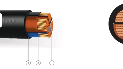
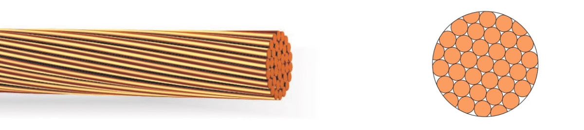
UNE 22510 cables utilize highly flexible stranded conductors to ensure operational reliability under constant movement and flexing:
• Class 5: Flexible for semi-mobile applications
• Class 6: Extra flexible for highly dynamic applications
• Tinning provides corrosion resistance in humid environments
• 0.5 mm² to 300 mm² for flexible cables
• 35 mm² to 630 mm² for power distribution
• AWG 20 to AWG 2/0 equivalent
• Protective earth: Yellow-green or separate copper conductors
• Pilot conductors: For control and monitoring signals
• Individual wire diameter: 0.1-0.2 mm
• Stranding factor: >80 wires per mm²
• Optimized for minimum flex life of 2 million cycles
4.2 Insulation Systems
The choice of insulation material significantly impacts cable performance and longevity in mining environments:
| Insulation Type | Material | Temperature Rating | Key Advantages | Typical Applications |
|---|---|---|---|---|
| V (PVC) | Polyvinyl Chloride Type B | -15°C to +80°C | Cost-effective, good electrical properties, flame retardant | Fixed installations, rigid armored cables (VVMV series) |
| D (EPR) | Ethylene Propylene Rubber Type 3GI3 | -25°C to +90°C | Excellent flexibility, superior weather resistance, ozone resistant | Flexible cables, trailing applications (DS1N, DM2N series) |
| R (XLPE) | Cross-Linked Polyethylene | -40°C to +90°C | Outstanding thermal stability, low dielectric loss, moisture resistant | High-voltage distribution, long-term fixed installations |
4.3 Screening and Shielding Systems
For medium and high voltage cables operating in electrically noisy environments, UNE 22510 specifies comprehensive screening systems:
Source: UNE 22510:1996 § 5.3 – Screening Requirements for Mining Cables
4.4 Armoring Systems
Mechanical protection is critical for cables subjected to extreme mining conditions:
| Armor Code | Armor Type | Construction Details | Protection Level |
|---|---|---|---|
| M | Normalized Galvanized Steel Wire | Round galvanized steel wires laid helically, counter-spiral with steel strap | High – Maximum crush and impact resistance |
| M1 | Special Galvanized Steel Wire | Enhanced wire gauge for extreme conditions | Very High – Quarries and surface mining |
| M2 | Flexible Galvanized Steel Wire | Stranded wire construction for flexible applications, copper conductance equivalency | High – Flexible trailing cables with mechanical protection |
| MV | PVC-Coated Steel Wire | Individual PVC coating on each armor wire | High – Enhanced corrosion protection for wet environments |
4.5 Outer Sheath Materials
| Sheath Code | Material | Properties | Typical Applications |
|---|---|---|---|
| N | Polychloroprene (PCP) or Similar | Excellent oil, ozone, weather resistance; Self-extinguishing; -40°C to +85°C | Flexible cables, outdoor applications, mobile equipment |
| V | Polyvinyl Chloride (PVC) Type ST2 | Good flame retardancy; Chemical resistant; Cost-effective; -15°C to +80°C | Fixed installations, rigid armored cables, underground galleries |
5. Cable Code Designation System
5.1 Understanding UNE 22510 Cable Codes
The UNE 22510 standard employs a systematic alphanumeric designation system that provides complete information about cable construction. The designation follows this structure:
[INSULATION][SCREEN][ARMOR][SHEATH] [VOLTAGE] ([CONDUCTOR CONFIGURATION]) [CONDUCTOR TYPE]
5.2 Designation Code Components
1st Position – Insulation Type:
2nd Position – Screening System:
3rd Position – Armoring Type:
4th Position – Outer Sheath:
Conductor Configuration Notation:
Conductor Type Suffix:
5.3 Practical Designation Examples
Example 1: VVMV 3.6/6 kV (3×95) K
Decoding:
- V – PVC insulation
- V – PVC sealing/filler layer
- M – Galvanized steel wire armor
- V – PVC outer sheath
- 3.6/6 kV – Nominal voltage U₀/U
- (3×95) – Three 95 mm² conductors
- K – Compact copper conductors
Application: Rigid armored cable for fixed underground installations requiring medium voltage distribution
Example 2: DM2N 0.6/1 kV (3×50+3×10+3×4 P) F
Decoding:
- D – EPR insulation
- M2 – Flexible galvanized steel wire cable armor
- N – Polychloroprene (PCP) outer sheath
- 0.6/1 kV – Nominal voltage U₀/U
- (3×50+3×10+3×4 P) – Three 50 mm² phase conductors + three 10 mm² protective conductors + three 4 mm² pilot conductors
- F – Flexible stranded copper conductors
Application: Flexible armored trailing cable for mobile mining equipment with integrated control circuits
Example 3: DS1N 0.6/1 kV (3×25+3×10+3×1.5 D) F
Decoding:
- D – EPR insulation
- S1 – Individual semiconductor screen on each insulated main conductor
- N – Polychloroprene outer sheath
- 0.6/1 kV – Nominal voltage
- (3×25+3×10+3×1.5 D) – Three 25 mm² phase conductors + three 10 mm² protective conductors + three 1.5 mm² drain conductors
- F – Flexible stranded conductors
Application: Flexible screened cable for electrically noisy environments, preventing EMI in sensitive control systems
6. Compliance with International Standards
6.1 Harmonization with Global Standards
While UNE 22510 is a Spanish national standard, it has been developed in harmony with numerous international standards to ensure global compatibility and acceptance. According to European Standards, UNE 22510:1996 incorporates requirements from multiple authoritative bodies:
| Standard Family | Specific Standards | Scope of Application | Key Requirements Adopted |
|---|---|---|---|
| IEC (International Electrotechnical Commission) |
• IEC 60228 – Conductors • IEC 60502-1 – Low voltage power cables • IEC 60502-2 – Medium voltage cables • IEC 60332 series – Flame retardancy • IEC 60754 series – Halogen content • IEC 61034 – Smoke emission | Global electrical safety and performance standards | Conductor classifications, insulation requirements, fire performance testing protocols |
| DIN VDE (German Standards) |
• DIN VDE 0250-813 – Mining cables • DIN VDE 0207 – Insulation materials • DIN VDE 0298-3 – Installation practices • DIN VDE 0295 – Conductor specifications | German industrial and mining cable requirements | Mechanical stress testing, temperature ratings, construction details |
| EN (European Norms) |
• EN 50525-2-21 – Flexible cables • EN 60332-3-24 – Vertical flame spread • EN 60811 series – Testing methods • EN 50363 – Polyurethane compounds | European Union cable standards | Manufacturing consistency, testing methodologies, material specifications |
| ICEA (Insulated Cable Engineers Association) |
• ICEA S-75-381 – Portable and power feeder cables for mines • ICEA S-95-658 – Heavy-duty cables | North American mining cable standards | Ampacity calculations, construction requirements, performance criteria |
| MSHA (Mine Safety and Health Administration) |
• 30 CFR Part 18 – Electric motor-driven mine equipment • 30 CFR Part 75 – Underground coal mines | United States mining safety regulations | Flame resistance, ground-check monitoring, trailing cable specifications |
| AS/NZS (Australian/New Zealand Standards) |
• AS/NZS 1802:2003 – Mining cables • AS/NZS 2802:2000 – Trailing cables | Australia and New Zealand mining operations | Flexibility requirements, durability testing, regional compliance |
6.2 Related UNE Mining Cable Standards
UNE 22510 serves as the foundation standard, with supplementary standards addressing specific cable types:
Specifications for fixed installation cables with steel wire or tape armor, typically for permanent underground galleries and distribution systems
Requirements for trailing cables with flexible armor for mobile mining equipment, shuttle cars, and continuous miners
Divided into three parts (22513-1, 22513-2, 22513-3) covering different configurations of flexible cables without mechanical armor
Specifications for data, voice, and control signal cables used in underground communication networks
6.3 Quality Management and Certification
Manufacturers of UNE 22510 compliant cables must maintain rigorous quality management systems:
- ISO 9001:2015 – Quality management system certification ensuring consistent manufacturing processes
- ISO 14001:2015 – Environmental management system for sustainable cable production
- RoHS II Directive 2011/65/EU – Free of harmful substances (lead, mercury, cadmium, hexavalent chromium)
- ATEX Certification – For cables used in potentially explosive atmospheres (zones with methane/coal dust)
- CE Marking – European Conformity for sales within EU markets
- EAC Certification – Eurasian Conformity for Russian and CIS markets
7. Safety Thresholds and Requirements
7.1 Critical Safety Parameters
Underground mining environments present unique hazards that demand strict adherence to safety thresholds. Research from the U.S. Mine Safety and Health Administration emphasizes the importance of electrical safety standards for preventing fires, explosions, and shock hazards.
7.2 Ground Fault Protection
Ground-Check Monitoring System Requirements:
- Ground continuity monitoring: Dedicated ground-check conductor (minimum 16 AWG per MSHA standards)
- Monitoring resistance: Maximum 1 ohm for effective ground fault detection
- Response time: Ground fault protection device must trip within 40 milliseconds
- Sensitivity threshold: Ground fault current detection at 20-30 mA for personnel protection
- Pilot monitoring: Automatic equipment shutdown if ground circuit integrity is lost
7.3 Voltage Drop and Power Quality
| Parameter | Maximum Threshold | Consequence of Exceeding | Mitigation Strategy |
|---|---|---|---|
| Voltage Drop (Low Voltage) | 5% of nominal voltage | Equipment malfunction, motor overheating, reduced performance | Proper conductor sizing, minimize cable length, optimize routing |
| Voltage Drop (Medium Voltage) | 3% of nominal voltage | Transformer inefficiency, equipment damage, power quality issues | Calculate ampacity per ICEA S-75-381 tables, use larger conductors |
| Insulation Resistance (Initial) | Minimum 20 MΩ @ 500V DC | Current leakage, shock hazard, premature cable failure | Regular megger testing, maintain proper installation practices |
| Insulation Resistance (Service) | Minimum 1 MΩ @ 500V DC | Ground faults, electrical fires, equipment damage | Periodic testing, moisture protection, proper cable handling |
7.4 Temperature Limits and Thermal Management
⚠️ Critical Temperature Thresholds:
| Condition | PVC Insulation | EPR/XLPE Insulation | Safety Implications |
|---|---|---|---|
| Maximum Operating Temperature | 80°C | 90°C | Exceeding causes accelerated aging, insulation degradation |
| Emergency Overload (15 min) | 100°C | 105°C | Temporary overload – not for continuous operation |
| Short Circuit (5 seconds max) | 160°C | 250°C | Protective devices must clear fault within time limit |
| Minimum Installation Temperature | -5°C | -25°C | Below limits risks insulation cracking, sheath damage |
7.5 Cable Current Carrying Capacity (Ampacity)
Proper ampacity calculation is essential for safety and performance. According to industry standards, ampacity values are based on:
- Conductor temperature: 90°C for EPR/XLPE, 80°C for PVC
- Ambient temperature: Typically 30°C (adjustable with correction factors)
- Installation method: Laid on ground, in trays, buried in conduit
- Grouping factor: Derating when multiple cables run together
- Thermal resistivity: Soil/ambient medium thermal characteristics
| Conductor Size | Ampacity (Single Cable, EPR, 90°C) | Ampacity (Bundled 3 Cables, 80% Factor) | Max. Motor Size (kW @ 415V) |
|---|---|---|---|
| 16 mm² / 6 AWG | 75 A | 60 A | 30 kW |
| 25 mm² / 4 AWG | 100 A | 80 A | 45 kW |
| 35 mm² / 2 AWG | 125 A | 100 A | 55 kW |
| 50 mm² / 1 AWG | 160 A | 128 A | 75 kW |
| 70 mm² / 2/0 AWG | 210 A | 168 A | 110 kW |
| 95 mm² / 3/0 AWG | 260 A | 208 A | 150 kW |
| 120 mm² / 4/0 AWG | 305 A | 244 A | 185 kW |
| 150 mm² | 355 A | 284 A | 220 kW |
| 185 mm² | 415 A | 332 A | 260 kW |
| 240 mm² | 500 A | 400 A | 315 kW |
Note: Ampacity values are approximate and based on IEC 60502-1 / ICEA S-75-381. Always consult manufacturer specifications and apply appropriate derating factors for your specific installation conditions.
8. Installation and Usage Precautions
8.1 Cable Handling and Installation Best Practices
⚠️ Critical Installation Requirements:
8.1.1 Minimum Bend Radius
- Fixed installation: Minimum 10-12 × outer diameter for armored cables, 6-8 × for non-armored
- Flexible/mobile applications: Minimum 10-15 × outer diameter to prevent conductor damage
- Reeling drum diameter: Minimum 20-25 × outer diameter for continuous motion applications
- Never exceed bending limits: Violating minimum bend radius voids warranty and causes premature failure
8.1.2 Cable Pulling and Tensile Stress
- Maximum pulling tension: Not to exceed 5 kg per mm² of total conductor cross-section
- Use proper cable grips: Never pull cables by outer sheath alone – use approved mesh grips
- Pulling speed: Maximum 10-15 meters per minute to avoid dynamic stress concentration
- Use rollers and guides: Support cable every 1.5-2 meters during installation to distribute weight
- Lubrication: Apply approved cable pulling lubricant to reduce friction (avoid petroleum-based products)
8.1.3 Storage and Transportation
- Temperature range: Store at +5°C to +50°C to prevent insulation damage
- Drum storage: Store drums vertically on flat surfaces, never stack more than 2 high
- UV protection: Cover outdoor storage with opaque tarps – UV exposure degrades sheathing
- Moisture protection: Seal drum ends with plastic caps, store in dry ventilated areas
- Rotation frequency: Rotate stored drums every 3 months to prevent conductor deformation
- Inspection before use: Visually inspect for cracks, cuts, or sheath damage before installation
8.2 Cable Termination and Splicing
Proper termination is critical for maintaining cable integrity and safety. According to U.S. Code of Federal Regulations 30 CFR Part 75, specific procedures must be followed:
• Maintain IP66/IP67 ingress protection at all terminations
• Apply stress relief to prevent conductor pull-out
• Properly size earth/ground connections (equivalent to phase conductor)
• Verify contact resistance <10 milliohms at all connections
• Use manufacturer-approved splice kits with proper insulation restoration
• Restore screens/shields across splice – no gaps in electromagnetic protection
• Document all splice locations and inspection dates
• Test insulation resistance (min. 20 MΩ) after completion
• Apply 2.0 × rated voltage + 1000V for 5 minutes
• Record all test results in permanent maintenance log
• Implement periodic inspection schedule (minimum quarterly)
• Train personnel in proper splicing techniques per MSHA requirements
• Implement lockout/tagout (LOTO) procedures per OSHA 29 CFR 1910.147
• Verify zero-energy state with calibrated test equipment
• Discharge residual capacitance before touching conductors
• Use insulated tools rated for working voltage
8.3 Operational Monitoring and Maintenance
| Inspection Item | Frequency | Acceptance Criteria | Action if Failed |
|---|---|---|---|
| Visual Inspection | Daily (mobile equipment) Weekly (fixed installations) | No visible cuts, abrasions >10% sheath thickness, crushing, or deformation | Mark damaged section, assess severity, repair or replace within 24-48 hours |
| Ground Continuity Test | Daily before equipment operation | Ground circuit resistance <1 ohm, ground-check monitor functioning | Do not operate equipment, inspect ground conductors, repair immediately |
| Insulation Resistance (Megger Test) | Monthly (minimum) After any suspected damage | Phase-to-phase: >20 MΩ @ 500V DC Phase-to-ground: >20 MΩ @ 500V DC | Remove from service, locate fault using TDR, repair or replace cable |
| Thermal Imaging | Quarterly (high-load circuits) Annually (all circuits) | No hot spots >15°C above ambient, uniform temperature distribution | Investigate high-resistance connections, check for overloading, repair terminations |
| Flexing/Fatigue Assessment | Every 6 months (mobile cables) | No conductor strand breakage, no significant reduction in flexibility | Rotate cable position on drum, replace if >10% conductor strands broken |
| Protective Device Testing | Annually (minimum) | Ground fault trip <40ms @ 30mA, overcurrent protection functioning correctly | Calibrate or replace protective devices, verify settings per manufacturer specs |
8.4 Environmental Considerations
Insights from reeling cable specialists emphasize the importance of understanding environmental impacts:
- Water exposure: While cables are rated AD5 (water jets), avoid continuous submersion unless specifically rated AD8
- Chemical exposure: Verify compatibility with specific mining chemicals – keep chemical compatibility chart readily available
- Temperature extremes: Monitor ambient temperatures, apply derating factors when operating >30°C or <0°C
- Mechanical abuse: Implement cable runover protection, use cable protectors in high-traffic areas
- Electromagnetic interference: Use screened cables (S1, S2, H types) near VFDs, welders, or high-power equipment
9. Common Problems and Solutions
9.1 Frequently Encountered Cable Failures
| Problem | Symptoms | Root Causes | Solutions | Prevention |
|---|---|---|---|---|
| Conductor Break (Mechanical Fatigue) | Intermittent power loss, voltage fluctuations, equipment shutdown | Excessive flexing beyond design limits, sharp bends, improper reeling | Locate break using TDR, cut out damaged section, install approved splice | Adhere to minimum bend radius, use proper reeling drums, rotate cable position periodically |
| Insulation Breakdown | Ground faults, protective device tripping, reduced insulation resistance | Water ingress through damaged sheath, overheating, chemical attack, aging | Megger test to locate fault zone, replace affected cable section, dry out if moisture-related | Regular insulation testing, proper sealing at terminations, avoid overloading, control ambient temperature |
| Sheath Damage/Abrasion | Visible cuts or wear on outer jacket, exposed armor or conductors | Dragging over rough surfaces, equipment runover, improper storage | Apply sheath repair tape for minor damage (<20% thickness), replace cable if armor exposed | Use cable protectors/mats in high-traffic areas, implement proper cable routing, train operators |
| Ground-Check Circuit Failure | Ground monitor alarm, equipment will not start, loss of ground continuity | Corroded connections, broken drain wire, damaged ground conductor | Inspect all ground connections, clean corrosion, repair or replace ground conductors | Apply corrosion inhibitor at connections, use tinned copper, seal terminations properly |
| Overheating at Terminations | Hot spots detected on thermal imaging, discolored insulation, melted components | Loose connections, undersized terminals, high resistance joints, oxidation | De-energize, disassemble termination, clean contacts, apply proper torque, replace damaged parts | Use calibrated torque wrenches, apply anti-oxidant compound, periodic thermal inspection |
| Screen/Shield Degradation | Electromagnetic interference affecting control systems, erratic equipment behavior | Damaged shield continuity, improper grounding, corrosion at screen terminations | Test shield continuity, repair shield connections, ensure proper single-point grounding | Protect shield during installation, maintain shield continuity at splices, regular continuity checks |
| Armor Wire Breakage | Protruding wires puncturing sheath, loss of mechanical protection | Excessive bending stress, corrosion of galvanized coating, fatigue from cyclic loading | Wrap damaged area with armor repair tape if <5 wires broken, replace cable if extensive | Use cables with appropriate armor type for application, avoid tight bends, control corrosive exposure |
| Moisture Ingress | Reduced insulation resistance, condensation visible in cable, corrosion of conductors | Unsealed terminations, damaged sheath, capillary action along conductors | Identify entry point, seal all terminations, dry cable using low-heat method if salvageable | Use IP-rated cable glands, apply heat-shrink boots, seal all penetrations, proper drainage |
9.2 Troubleshooting Workflow
Step-by-Step Diagnostic Procedure:
- Immediate Actions (Safety First):
- De-energize affected circuit using proper lockout/tagout procedures
- Evacuate personnel if smoke, burning smell, or shock hazard present
- Notify mine supervisor and electrical maintenance team
- Secure area to prevent unauthorized access
- Initial Assessment:
- Review equipment operating logs and recent maintenance records
- Interview equipment operators about symptoms and timeline
- Visually inspect entire cable length for obvious damage
- Check protective device operation and settings
- Electrical Testing:
- Verify zero voltage at cable using calibrated multimeter
- Perform insulation resistance test (megger) on all conductors
- Check ground continuity – should be <1 ohm end-to-end
- Measure conductor resistance – compare to manufacturer specifications
- Use Time Domain Reflectometer (TDR) to locate faults if resistance tests fail
- Physical Inspection:
- Inspect all terminations for loose connections, corrosion, overheating signs
- Check cable routing for improper bends, crushing points, or abrasion zones
- Examine armor and sheath for cuts, punctures, or fatigue cracks
- Verify minimum bend radius compliance at all transition points
- Corrective Action:
- For minor damage (<20% sheath thickness): Apply approved repair materials
- For conductor/insulation damage: Replace affected section or entire cable
- For termination issues: Clean, retorque, or replace connection components
- Document all findings, repairs, and test results in maintenance log
- Verification and Return to Service:
- Perform insulation resistance test after repairs (minimum 20 MΩ)
- Conduct high-potential (hi-pot) test if code requires
- Test ground-check circuit functionality
- Energize cable under no-load conditions, monitor for 30 minutes
- Apply load gradually while monitoring temperature and performance
- Brief operators on repairs and schedule follow-up inspection
9.3 When to Replace vs. Repair
⚠️ Replacement Criteria (Do NOT Attempt Repair):
- ❌ More than 10% of conductor strands broken in any section
- ❌ Insulation resistance consistently below 1 MΩ despite drying attempts
- ❌ Multiple splice points (>3 splices per 100 meters reduces reliability)
- ❌ Armor penetration exposing conductors to environment
- ❌ Extensive sheath damage (>30% circumference or >50% wall thickness)
- ❌ Thermal damage indicated by discolored or melted insulation
- ❌ Evidence of internal water tracking (persistent low insulation resistance)
- ❌ Age exceeding manufacturer’s recommended service life (typically 10-15 years for mining cables)
- ❌ Cable has been subjected to short-circuit current exceeding I²t rating
10. Technical Specifications Table
10.1 Comprehensive Cable Specifications by Type
The following table provides detailed technical specifications for common UNE 22510 compliant mining cables, based on actual manufacturing data:
| Cable Type | Voltage Rating | Conductor Configuration | Conductor Size Range | Insulation Material | Armor Type | Applications |
|---|---|---|---|---|---|---|
| VVMV 0.6/1 kV (K) | 0.6/1 kV | 3-core + PE | 10-300 mm² | PVC Type B | Galvanized steel wire + copper core + counter-spiral steel strap | Fixed underground distribution, permanent galleries, stationary equipment |
| VVMV 3.6/6 kV (K) | 3.6/6 kV | 3-core | 35-240 mm² | PVC Type B | Galvanized steel wire + copper core + counter-spiral steel strap | Medium voltage distribution, main feeder cables, primary electrical infrastructure |
| DM2N 0.6/1 kV (F) | 0.6/1 kV | 3-core + 3×PE | 16-240 mm² | EPR Type 3GI3 | Flexible galvanized steel wire cable + copper equivalency | Mobile equipment, trailing cables, shuttle cars, continuous miners |
| DM2N Pilot 0.6/1 kV (F) | 0.6/1 kV | 3×power + 3×PE + 3×pilot | Power: 25-150 mm² Pilot: 1.5-10 mm² | EPR | Flexible galvanized steel wire cable | Mobile equipment with remote control, automated mining machinery |
| DS1N 0.6/1 kV (F) | 0.6/1 kV | 3-core + 3×PE + drains | 10-95 mm² | EPR | Individual semiconductor screen (S1) | Electrically noisy environments, VFD-fed equipment, precision control systems |
| DN/3E 0.6/1 kV (F) | 0.6/1 kV | 3×power + 3×PE + 3×pilot | 35-150 mm² | EPR | None (flexible non-armored) | Protected environments, cable galleries, overhead installations |
10.2 Detailed Construction Specifications Example
Example: DM2N 0.6/1 kV (3×95+3×50/3E) F Cable – Detailed Breakdown
| Component | Specification | Standard Reference |
|---|---|---|
| Power Conductors (3×) | 95 mm² tinned copper, Class 5 flexible, 504 strands × 0.21mm wire diameter | IEC 60228 Class 5 |
| Protective Earth Conductors (3×) | 50 mm² tinned copper, Class 5 flexible, divided into three separate conductors | IEC 60228 Class 5 |
| Conductor Identification | Brown, Black, Grey (power); Yellow-Green (earth) | UNE 21089-1, HD 308 |
| Insulation Material | EPR Type 3GI3, thickness 2.2mm, black color | DIN VDE 0207-20 |
| Cradle Separator | Textile material with Kevlar reinforcement in center | Manufacturer specification |
| Inner Covering | Rubber compound filler, semiconductive properties | UNE 22512 § 6.4 |
| Armor Layer | Galvanized steel wire cables, conductance ≥50% of phase conductor, flexible construction | UNE 22512 § 7.2 |
| Outer Sheath | Polychloroprene (PCP) Type 5GM5, thickness 3.5mm, black color | DIN VDE 0207-21 |
| Approximate Outer Diameter | 55-60 mm | Calculated per UNE 22512 |
| Approximate Weight | 8.5-9.5 kg/m | Manufacturer data |
| Copper Content | ≈430 kg/km (power + earth) | Calculated value |
| Test Voltage | 3,500 V AC for 5 minutes | UNE 22512 § 9.2 |
| Minimum Bend Radius (Fixed) | 600 mm (10 × OD) | UNE 22512 Table 3 |
| Minimum Bend Radius (Flexible) | 600 mm (10 × OD) | UNE 22512 Table 3 |
11. References and Citations
11.1 Primary Standards and Regulatory Documents
- UNE 22510:1996 – Electric Cables for Underground Mining. General Requirements. Spanish Association for Standardization and Certification (AENOR), November 24, 1996.
- European Standards Reference – UNE 22510:1996 Classification: ICS 29.060.20 (Cables) and 73.100.99 (Other mining equipment).
- Mining Cable: The Complete Guide – Comprehensive analysis of mining cable standards including IEC 60092 series, MSHA, IEEE 525, CSA, and ATEX requirements. TOT Cables, May 2025.
- 30 CFR Parts 18 and 75 – High-Voltage Continuous Mining Machine Standard for Underground Coal Mines. U.S. Mine Safety and Health Administration, Federal Register Vol. 75, No. 65, April 6, 2010.
- 30 CFR Part 75 Subpart I – Underground High-Voltage Distribution. Electronic Code of Federal Regulations, U.S. Government Publishing Office.
11.2 International Standards References
- IEC 60228 – Conductors of insulated cables. International Electrotechnical Commission.
- IEC 60502-1 – Power cables with extruded insulation and their accessories for rated voltages from 1 kV up to 30 kV – Part 1: Cables for rated voltages of 1 kV and 3 kV.
- IEC 60502-2 – Power cables with extruded insulation and their accessories for rated voltages from 1 kV up to 30 kV – Part 2: Cables for rated voltages from 6 kV up to 30 kV.
- IEC 60332-1-2 – Tests on electric and optical fibre cables under fire conditions – Test for vertical flame propagation for a single insulated wire or cable.
- IEC 60332-3-24 – Tests on electric and optical fibre cables under fire conditions – Test for vertical flame spread of vertically-mounted bunched wires or cables – Category C.
- IEC 60754-1 – Test on gases evolved during combustion of materials from cables – Determination of the halogen acid gas content.
- IEC 60754-2 – Test on gases evolved during combustion of materials from cables – Determination of the degree of acidity of gases by measuring pH and conductivity.
- IEC 61034-2 – Measurement of smoke density of cables burning under defined conditions – Test procedure and requirements.
- DIN VDE 0250-813 – Cables and cords – Flexible cables and cords for mining purposes.
- DIN VDE 0207 – Insulating materials and sheaths for cables and flexible cords.
- DIN VDE 0298-3 – Use of cables and cords in power installations – Selection and erection.
- ICEA S-75-381 – Portable and Power Feeder Cables for Use in Mines. Insulated Cable Engineers Association.
11.3 Industry Resources and Technical Publications
- Reeling Cable Solutions – Technical insights on flexible power cables for mobile machinery, reeling applications, and cable management systems in port terminals and industrial environments.
- Amplex Mining Cables Australia – Specialist manufacturer of AS/NZS compliant mining cables including Type 241, 209, 210, 240, 245, 260, 275, 409, 412, 440, 441, 450, and 455 cables for Australian mining operations.
- Cable Data Sheet Reference – UNE 22510 Cable Code Designation system explanation and technical consulting service.
- Mining Cable Basics – ATI Electrical, February 15, 2019. Overview of G-GC, SHD-GC, and MP-GC mining cable construction and applications.
- Cables for Underground Mining Projects – Henan Province Jianyun Cable Co., Ltd. Technical guide covering IEC 60502-1, IEC 60332-3, AS/NZS 2802 compliance.
- Tele-Fonika Mining Cables Catalogue – Comprehensive product specifications for mining cables including SHD-GC and flexible reeling cables.
11.4 Manufacturer Quality Standards
- ISO 9001:2015 – Quality management systems. Requirements for consistent manufacturing processes.
- ISO 14001:2015 – Environmental management systems. Sustainable cable production practices.
- RoHS II Directive 2011/65/EU – Restriction of Hazardous Substances in electrical and electronic equipment.
- Delegated Directive (EU) 2015/863 – Amendment to RoHS II Annex II regarding restricted substances.
📚 Additional Technical Resources Available:
Anhui Feichun Special Cable Co., Ltd. maintains comprehensive technical documentation including:
- UNE 22511/22512/22513 series standard interpretations
- Cable selection guides based on application requirements
- Installation manuals and best practices documentation
- Compatibility charts for chemicals, oils, and environmental conditions
- Test reports and certification documentation
- CAD drawings and technical specifications for custom designs
Contact our technical team for detailed documentation: