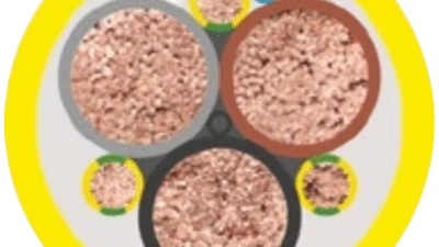
Complete Technical Guide to German Military-Grade Marine Cables

What is VG 95218 Cable?
Complete Technical Guide to German Military-Grade Marine Cables
Anhui Feichun Special Cable Co., Ltd. (安徽飞纯特种电缆有限公司)
As a premier manufacturer of specialized cables meeting international military and marine standards, Anhui Feichun Special Cable Co., Ltd. delivers high-performance VG 95218 certified cables for naval, defense, and critical marine applications. Our manufacturing capabilities encompass the complete VG 95218 specification range, incorporating advanced materials technology and rigorous quality control protocols to ensure compliance with German Bundeswehr standards and international maritime requirements.
[email protected]
[email protected]
WhatsApp: +86 13855123218
Table of Contents
- 1. Introduction to VG 95218 Standard
- 2. Cable Designation System
- 3. Technical Specifications by Part Number
- 4. Material Structure and Construction
- 5. BAAINBw Certification and Compliance
- 6. Applications and Use Cases
- 7. Safety Standards and Fire Performance
- 8. Installation Guidelines and Precautions
- 9. Common Issues and Troubleshooting
- 10. Maintenance and Testing Requirements
1. Introduction to VG 95218 Standard
VG 95218 represents a comprehensive German military specification governing cables and wires designed specifically for naval vessels operated by the Bundeswehr and other military organizations. Developed and maintained by the Federal Office of Bundeswehr Equipment, Information Technology and In-Service Support (Bundesamt für Ausrüstung, Informationstechnik und Nutzung der Bundeswehr, abbreviated as BAAINBw), this standard establishes stringent requirements for cable performance in the demanding maritime military environment. The specification encompasses multiple parts addressing various cable types, voltage ranges, and specialized applications, all unified by common principles of safety, reliability, and environmental resistance.
The VG 95218 standard emerged from the critical need to ensure electrical system reliability aboard naval vessels operating under extreme conditions. Marine environments present unique challenges including saltwater exposure, high humidity, temperature extremes, mechanical vibration, and the paramount concern of fire safety in confined spaces. According to industry documentation from major cable manufacturers including Prysmian and Friesland-Kabel, VG 95218 cables must demonstrate exceptional performance characteristics including halogen-free construction, low smoke emission, oil resistance, and superior electromagnetic compatibility. These requirements ensure that electrical and communication systems aboard military vessels maintain operational integrity during normal operations and, critically, during emergency scenarios.
Key Distinguishing Features of VG 95218 Cables
VG 95218 cables are distinguished from conventional marine cables through several critical performance requirements. The standard mandates halogen-free materials throughout the cable construction, which prevents the generation of corrosive and toxic hydrogen halide gases during fire events. This characteristic proves essential in submarine and surface vessel applications where personnel evacuation may be limited. The cables must meet stringent smoke density limitations per IEC 61034, ensuring visibility for emergency response and evacuation. Additionally, VG 95218 specifications require specific oil resistance characteristics per VG 95218-2, enabling cable operation in machinery spaces and areas exposed to petroleum products. The electromagnetic compatibility provisions, particularly in screened variants, ensure reliable signal transmission in electrically noisy naval environments where sensitive communication and control systems must operate without interference.
Historical Context and Development
The VG (Verteidigungsgerät, or defense equipment) standard series represents decades of refinement in military cable technology. The German military’s experience operating naval vessels in diverse conditions from Arctic waters to tropical regions informed the development of comprehensive performance criteria. The standard incorporates lessons learned from operational failures and safety incidents, evolving to address emerging technologies and changing threat profiles. Modern VG 95218 cables reflect advances in polymer chemistry, with cross-linked elastomeric compounds providing superior thermal and mechanical properties compared to earlier rubber formulations. The certification process administered by BAAINBw ensures that only cables meeting these exacting standards are approved for installation aboard German naval vessels and vessels constructed to German military specifications.
Halogen-Free Construction
All VG 95218 cables utilize halogen-free materials, preventing corrosive gas generation during fire events and ensuring safer evacuation conditions.
Low Fire Hazard
Cables meet stringent flame propagation, smoke density, and gas toxicity requirements per VG 95218-2 test protocols.
Oil and Chemical Resistance
Specialized compounds resist degradation from fuel, lubricants, and shipboard chemicals encountered in naval operations.
EMC Performance
Screened variants provide superior electromagnetic compatibility, essential for sensitive military communication and control systems.
2. Cable Designation System
The VG 95218 standard employs a systematic designation code that conveys comprehensive information about cable construction, application, and performance characteristics. Understanding this nomenclature proves essential for proper cable selection, procurement, and installation. Each letter in the designation carries specific meaning related to the cable’s intended use and construction details.
Code Structure and Interpretation
| Position | Code | Meaning | Application Context |
|---|---|---|---|
| First Letter(s) | M | Marine Power | Standard power cables for shipboard electrical distribution systems rated 0.6/1 kV |
| MM | Medium Voltage Marine | Medium voltage power cables rated 6/10 kV or 12/20 kV for primary distribution | |
| L | Light/Low Voltage Marine | Lightweight power or control cables rated 300/500 V for secondary distribution | |
| FM | Instrumentation Marine | Telecommunications and instrumentation cables rated 250 V for signal transmission | |
| LFM | Signaling Marine | Signaling and communication cables rated 250 V for data and voice systems | |
| Middle Letters | G | Gummi (Rubber) | Indicates rubber-based insulation or sheath material, typically EPR or cross-linked elastomeric compounds |
| S | Screen/Shield | Copper wire braid screen for electromagnetic shielding; multiple S indicate multiple screening layers | |
| E | Individual Core Screen | Each core or pair individually screened for enhanced electromagnetic compatibility | |
| Last Letter | O | Oil Resistant | Outer sheath formulated for resistance to oils, fuels, and petroleum-based chemicals |
Practical Designation Examples
MGSGO
- M – Marine power cable
- G – Rubber insulation
- S – Braided screen
- G – Rubber sheath
- O – Oil resistant
Application: Standard screened power cable for machinery spaces and electrical distribution, rated 0.6/1 kV per VG 95218 Part 60.
LMGSGO
- L – Lightweight/low voltage
- M – Marine application
- G – Rubber insulation
- S – Braided screen
- G – Rubber sheath
- O – Oil resistant
Application: Lightweight control cable for lighting and auxiliary systems, rated 300/500 V per VG 95218 Part 61.
FMGSGO
- F – Telecommunications/instrumentation
- M – Marine application
- G – Rubber insulation
- S – Braided screen
- G – Rubber sheath
- O – Oil resistant
Application: Instrumentation cable with quad formation for telecommunications, rated 250 V per VG 95218 Part 62.
LFMSGSGO
- L – Lightweight signaling
- F – Telecommunications
- M – Marine application
- S – First screen layer
- G – Rubber material
- S – Second screen layer
- G – Rubber sheath
- O – Oil resistant
Application: Individually screened pairs with overall screen for high-performance data transmission, rated 250 V per VG 95218 Part 65.
MMGSGSGO
- MM – Medium voltage marine
- G – Rubber insulation (EPR)
- S – Core screen
- G – Rubber bedding
- S – Overall screen
- G – Rubber sheath
- O – Oil resistant
Application: Single-core medium voltage power cable for primary distribution systems, rated 6/10 kV per VG 95218 Part 14A.
MMGSEGSGO
- MM – Medium voltage marine
- G – Rubber insulation (EPR)
- S – Core screen
- E – Individual core screen
- G – Rubber bedding
- S – Overall screen
- G – Rubber sheath
- O – Oil resistant
Application: Three-core medium voltage motor supply cable for variable frequency drive applications, rated 6/10 kV per VG 95218 Part 14B.
Complete Designation Example:
MGSGO 3 x 2.5 mm² 0.6/1 kV VG 95218 Part 60This designation specifies: Marine power cable (M) with rubber insulation (G), copper wire braid screen (S), rubber sheath (G), oil-resistant outer covering (O), constructed with three cores of 2.5 mm² cross-section, rated for 0.6/1 kV operation, manufactured according to VG 95218 Part 60 specification.
3. Technical Specifications by Part Number
The VG 95218 standard comprises multiple parts, each addressing specific cable types and voltage ranges. This segmentation ensures that cables are optimized for their intended applications while maintaining consistent safety and performance standards across the specification family. The following sections detail the technical requirements for each major part of the VG 95218 standard.
VG 95218 Part 60: MGSGO / MGGO (0.6/1 kV)
Part 60 Power Cables with and without Screen
Part 60 addresses the most commonly specified cables for shipboard power distribution, providing electrical power to lighting, equipment, and machinery throughout the vessel. These cables serve as the workhorse of naval electrical systems, installed in cable ways, conduits, and enclosed spaces below and above deck.
| Parameter | Specification | Standard/Method |
|---|---|---|
| Conductor Material | Electrolytic copper, round stranded, Class 2 or Class 5 | DIN EN 60228 |
| Insulation Material | Ethylene Propylene Rubber (EPR), cross-linked, halogen-free | VG 95218 Part 60 |
| Screen (MGSGO only) | Plain copper wire braid with transparent foil separator | VG 95218 Part 60 |
| Outer Sheath | Cross-linked elastomer compound, black, halogen-free | VG 95218 Part 60 |
| Rated Voltage (Uo/U) | 0.6/1 kV | VG 95218 Part 60 |
| Max Operating Voltage AC/DC | 0.7/1.2 kV AC | 0.9/1.8 kV DC | VG 95218 Part 60 |
| AC Test Voltage | 3.5 kV for 15 minutes | VG 95218 Part 60 |
| Operating Temperature | -30°C to +90°C continuous operation | VG 95218 Part 60 |
| Short Circuit Temperature | 250°C maximum (5 seconds duration) | VG 95218 Part 60 |
| Minimum Installation Temperature | -15°C | VG 95218 Part 60 |
| Bending Radius (Fixed Installation) | 4×D (flexible conductor) | 5×D (standard conductor) | VG 95218 Part 60 |
| Maximum Tensile Load | 50 N/mm² of conductor cross-section | VG 95218 Part 60 |
| Flame Propagation | IEC 60332-1 (single cable) and IEC 60332-3-24 Category C (bundled) | VG 95218-2 |
| Halogen Content | <0.5% (as HCl equivalent) | IEC 60754-1 |
| Smoke Density | Light transmission ≥60% | IEC 61034-1 |
| Gas Acidity | pH ≥4.3, conductivity <10 μS/mm | IEC 60754-2 |
Technical data sourced from VG 95218 Part 60 specification and confirmed by manufacturer datasheets from Prysmian, Nexans, and Üntel Kablo certified manufacturing facilities.
VG 95218 Part 61: LMGSGO (300/500 V)
Part 61 Lightweight Control and Lighting Cables
Part 61 cables provide power distribution for lighting systems, control circuits, and auxiliary equipment operating at reduced voltage levels. The lightweight construction facilitates installation in confined spaces and reduces overall vessel weight, a critical consideration in naval architecture.
| Parameter | Specification | Notes |
|---|---|---|
| Conductor | Copper, round stranded per VG 95218 Part 61 | Smaller conductor sizes compared to Part 60 cables |
| Insulation | Cross-linked polyalkene compound, halogen-free | Provides excellent electrical properties with reduced wall thickness |
| Screen | Plain copper wire braid with transparent foil | Standard for all Part 61 cables; no unscreened variant |
| Outer Sheath | Cross-linked elastomer compound, black | Provides mechanical and environmental protection |
| Rated Voltage | 300/500 V (Uo/U) | Suitable for secondary distribution and control circuits |
| Max Operating Voltage | AC: 0.318/0.55 kV | DC: 0.413/0.825 kV | Safety margin above rated voltage |
| AC Test Voltage | 2.5 kV for 15 minutes | Verification of insulation integrity |
| Operating Temperature | -30°C to +90°C | Matches Part 60 temperature range |
| Bending Radius | 5×D minimum | Consistent across all conductor classes |
VG 95218 Part 62-66: Communication and Instrumentation Cables
Parts 62 through 66 address specialized cables for telecommunications, instrumentation, and signaling applications. These cables incorporate advanced electromagnetic compatibility features essential for reliable data transmission in electrically noisy shipboard environments. The specifications differentiate between unscreened pairs, individually screened pairs, and various configurations optimized for specific signal types and crosstalk requirements.
Part 62
FMGSGO
Quad formation, unscreened pairs
NEXT: ≥90 dB @ 10 kHz
Part 63
FMSGSGO
Individually screened pairs
NEXT: ≥90 dB @ 10 kHz
Part 64
LFMGSGO / LFMGSSGO
Single/double screen, pairs
NEXT: ≥90 dB @ 10 kHz
Part 65
LFMSGSGO
Screened pairs + overall screen
NEXT: ≥100 dB @ 10 kHz
Part 66
LFMSGSSGO
Screened triples, double overall screen
NEXT: ≥100 dB @ 10 kHz
| Part | Cable Type | Voltage | Core Formation | Screening | Primary Application |
|---|---|---|---|---|---|
| 62 | FMGSGO | 250 V | Quads (4 cores twisted) | Overall screen only | General telecommunications, intercom systems |
| 63 | FMSGSGO | 250 V | Pairs with individual screens | Individual + overall | High-quality voice and data circuits |
| 64 | LFMGSGO/LFMGSSGO | 250 V | Pairs, unscreened individually | Single or double overall | Lighting control, signaling systems |
| 65 | LFMSGSGO | 250 V | Individually screened pairs | Individual + overall | Critical data transmission, SCADA systems |
| 66 | LFMSGSSGO | 250 V | Triples (3 cores twisted) | Individual + double overall | High-performance instrumentation, control |
VG 95218 Part 14: Medium Voltage Cables (6/10 kV)
Part 14A Single-Core Medium Voltage (MMGSGSGO)
Part 14A specifies single-core medium voltage cables for primary power distribution aboard naval vessels. These cables distribute power from main switchboards to secondary distribution panels and large equipment throughout the ship. The single-core construction enables three-phase systems to be installed with appropriate physical separation and provides flexibility in routing.
Part 14B Three-Core Motor Supply (MMGSEGSGO)
Part 14B addresses three-core medium voltage cables specifically designed for pulse-type static inverter-fed three-phase AC drives. Modern naval vessels increasingly employ variable frequency drives for propulsion and auxiliary systems, creating unique electrical stresses including high dv/dt transients and common-mode currents. The individual core screening specified in Part 14B mitigates these effects, ensuring reliable motor operation and extended cable service life.
| Parameter | Part 14A (Single-Core) | Part 14B (Three-Core) |
|---|---|---|
| Conductor | Copper, round stranded, Class 2 | Copper, round stranded, Class 2 |
| Insulation | Ethylene-Propylene Rubber (EPR) | Ethylene-Propylene Rubber (EPR) |
| Field Control | Inner and outer semiconductive layers | Inner and outer semiconductive layers |
| Core Screen | Copper wires/tapes per core | Individual copper wires/tapes per core |
| Overall Screen | Plain copper wire braid with foil | Plain copper wire braid with foil |
| Outer Sheath | Cross-linked polyolefin, red | Cross-linked polyolefin, red |
| Rated Voltage (Uo/U/Um) | 6/10/12 kV | 6/10/12 kV |
| AC Test Voltage | 21 kV for 15 minutes | 21 kV for 15 minutes |
| Operating Temperature | -30°C to +90°C | -30°C to +90°C |
| Bending Radius | 6×D minimum | 6×D minimum |
| Typical Application | Primary distribution, general loads | Variable frequency drive motor supply |
Medium voltage cable specifications reflect requirements for naval propulsion systems and high-power auxiliary equipment. The red outer sheath provides visual identification of medium voltage circuits, enhancing safety during maintenance operations.
4. Material Structure and Construction
The construction of VG 95218 cables reflects advanced materials science and manufacturing processes designed to meet the demanding requirements of naval service. Each layer serves specific electrical, mechanical, or environmental protection functions. Understanding the construction principles enables proper cable selection, installation, and maintenance practices.
Conductor Technology
VG 95218 cables employ electrolytic copper conductors meeting IEC 60228 classifications. Class 2 conductors provide the standard stranding for fixed installations, offering appropriate flexibility for cable routing while maintaining mechanical integrity. Class 5 conductors, with their finer stranding, are specified for applications requiring enhanced flexibility, such as connections to vibrating equipment or installations in confined spaces with tight bend radii. The conductors are typically tin-plated to prevent oxidation in the marine environment and facilitate soldering during termination. Conductor sizing follows standard metric cross-sections ranging from 0.5 mm² for signaling cables to 240 mm² or larger for power distribution circuits. According to industry documentation from Friesland-Kabel and böhm Kabel, proper conductor selection considers not only the steady-state current requirements but also fault current levels, voltage drop constraints, and installation conditions specified in BV 3400.
Insulation Systems
Ethylene Propylene Rubber (EPR)
- Application: Power cables Parts 60 and 14
- Temperature Rating: 90°C continuous, 250°C short circuit
- Dielectric Constant: Approximately 3.0-3.5
- Advantages: Excellent electrical properties, thermal stability, ozone resistance
- Cross-Linking: Peroxide or radiation cross-linking for enhanced mechanical properties
Cross-Linked Polyalkene
- Application: Control, instrumentation, and communication cables
- Temperature Rating: 90°C continuous operation
- Properties: Lower dielectric constant than EPR, excellent moisture resistance
- Benefits: Reduced wall thickness, lower capacitance, improved high-frequency performance
- Processing: Cross-linking via electron beam or silane chemistry
Both insulation systems employ halogen-free formulations, a critical requirement distinguishing VG 95218 cables from conventional marine cables. The absence of chlorine, bromine, and other halogens prevents the generation of hydrogen halide gases during combustion. Traditional PVC-insulated cables, when burned, produce hydrogen chloride (HCl) gas, which is corrosive to electronic equipment and presents serious inhalation hazards. VG 95218’s halogen-free requirement ensures that fire scenarios do not compromise ship systems through corrosive gas attack and improves survivability for personnel in smoke-filled compartments.
Electromagnetic Screening
Electromagnetic compatibility represents a critical concern aboard naval vessels where sensitive communication, navigation, and weapons systems must operate reliably despite high levels of electrical noise from propulsion systems, radar, and other equipment. VG 95218 cables incorporate various screening configurations to address these challenges. The basic screen construction consists of a plain copper wire braid applied over the insulated cores, typically achieving 85-95% coverage. This braid provides a low-impedance path for induced currents and shields the signal conductors from external electromagnetic interference. A transparent polymer film separates the braid from adjacent layers, preventing contact that could compromise the screen’s effectiveness.
Advanced Screening Configurations
Communication and instrumentation cables specified in Parts 62-66 employ progressively more sophisticated screening approaches. Part 63 cables feature individual copper wire braid screens over each twisted pair, with an additional overall screen encompassing the entire cable. This dual-screen architecture provides superior crosstalk rejection, enabling the cable to meet the stringent near-end crosstalk attenuation (NEXT) requirement of 90 dB at 10 kHz. Part 65 and 66 cables achieve even higher NEXT performance (100 dB at 10 kHz) through optimized pair/triple geometry and enhanced screening. These performance levels prove essential for digital communication systems and precision instrumentation where signal integrity directly impacts system functionality.
For medium voltage applications, Part 14 cables incorporate metallic screens serving dual purposes. The screen provides electromagnetic shielding while simultaneously functioning as the fault current return path. The screen cross-section is carefully sized based on the anticipated fault current magnitude and duration, typically ranging from 16 mm² to 50 mm² for cables rated 95-240 mm² conductor size. Modern naval installations increasingly specify cables with individually screened cores (Part 14B designation) for variable frequency drive applications. The individual core screens mitigate the high-frequency common-mode currents generated by pulse-width modulated inverters, preventing bearing currents in connected motors and reducing radiated electromagnetic interference.
Outer Sheath Technology
The outer sheath provides the final line of defense against environmental hazards including mechanical damage, moisture ingress, oil and chemical exposure, and ultraviolet radiation. VG 95218 cables employ cross-linked elastomeric compounds formulated to deliver a comprehensive performance envelope. These compounds typically consist of a base polymer (such as chlorinated polyethylene, ethylene-vinyl acetate, or specialized polyolefin blends) combined with flame retardant additives, stabilizers, and processing aids. The cross-linking process, accomplished through peroxide chemistry or radiation exposure, creates three-dimensional molecular networks that substantially improve mechanical strength, abrasion resistance, and thermal stability compared to thermoplastic sheaths.
| Property | VG 95218 Requirement | Test Method | Significance |
|---|---|---|---|
| Oil Resistance | No significant degradation after immersion | VG 95218-2 / EN 60811-404 | Enables installation in machinery spaces with oil/fuel exposure |
| Ozone Resistance | No cracking after 24h exposure at 40°C | VG 95218-2 / EN 50363-1/2-1 | Ensures long-term integrity in ozone-rich environments (electrical equipment) |
| Abrasion Resistance | Minimum cycles before insulation exposure | EN 60811-404 | Withstands handling and installation stresses |
| Cold Flexibility | No cracking at -15°C (installation) / -30°C (service) | VG 95218-2 | Permits installation and operation in cold climates |
| Heat Aging | Retain 60% of initial properties after accelerated aging | EN 60811-401 | Predicts long-term service life under thermal stress |
The oil resistance characteristic merits particular attention given the shipboard environment. Cables installed in machinery spaces encounter various petroleum products including fuel oil, lubricating oil, hydraulic fluid, and cleaning solvents. Standard cable sheaths can soften, swell, or crack when exposed to these substances, compromising mechanical integrity and potentially allowing moisture ingress to the insulation. VG 95218’s oil resistance requirement, verified through standardized immersion testing per EN 60811-404, ensures that the sheath maintains its protective function throughout the cable’s service life. This characteristic extends to resistance against various shipboard chemicals including de-icing fluids, battery electrolyte, and bilge water contaminants.
Water-Blocking Technology
Selected VG 95218 applications, particularly those involving submarine or external hull installations, incorporate longitudinal water-blocking features. These cables employ water-swellable tapes or compounds strategically placed within the cable construction. Upon contact with water, these materials expand dramatically, filling voids and preventing water migration along the cable length. This technology proves critical for cables penetrating pressure hulls or installed in areas subject to flooding, as it prevents water from traveling along the cable into adjacent compartments. The water-blocking effectiveness is verified through pressure testing, with specifications typically requiring the cable to withstand 15 meters of water column pressure without longitudinal water penetration exceeding defined limits.
5. BAAINBw Certification and Compliance
The Federal Office of Bundeswehr Equipment, Information Technology and In-Service Support (Bundesamt für Ausrüstung, Informationstechnik und Nutzung der Bundeswehr, or BAAINBw) serves as the certification authority for VG 95218 cables. This organization establishes and maintains the VG standard series, conducts type approval testing, and oversees manufacturing quality control for approved products. The rigorous certification process ensures that cables installed aboard German naval vessels and vessels constructed to German military specifications meet uncompromising performance and safety standards.
Certification Process and Requirements
Manufacturers seeking VG 95218 certification must submit their cables to comprehensive type testing conducted by BAAINBw-approved test facilities. The type approval process evaluates cables against all requirements specified in the relevant VG 95218 part, including electrical performance, mechanical properties, environmental resistance, and fire safety characteristics. According to documentation from Prysmian Group and other certified manufacturers, the testing protocol encompasses dozens of individual tests performed on representative samples. Successful completion of type testing results in issuance of a Certificate of Approval according to VG 95211, the umbrella specification governing approval procedures for electrical cables and wires used by the Bundeswehr.
BAAINBw Certificate Significance
The BAAINBw certificate represents more than simple test report documentation. It signifies that the cable design, materials, and manufacturing processes have been evaluated and found compliant with German military requirements. The certificate includes detailed specifications of the approved cable construction, permissible tolerances, and any restrictions on application. Manufacturers must maintain production conformity with the approved design, with ongoing surveillance testing and periodic factory audits verifying continued compliance. This quality assurance framework ensures that cables bearing VG 95218 designation perform consistently regardless of production batch or time of manufacture. For shipbuilders and naval operators, the BAAINBw certificate provides confidence that installed cables will deliver reliable performance throughout their design life.
Relationship to Other Marine Standards
VG 95218 cables often carry multiple certifications reflecting their suitability for various marine applications. Many cables hold approval from classification societies including Germanischer Lloyd (now DNV), Bureau Veritas, Lloyd’s Register, and American Bureau of Shipping. These approvals demonstrate compliance with international marine cable standards and facilitate the use of VG 95218 cables on civilian vessels or naval vessels of other nations. The compatibility between VG 95218 and classification society requirements stems from shared safety principles, though VG 95218 often imposes more stringent performance criteria in areas such as fire safety and electromagnetic compatibility.
The BV 3400 specification (Specification for Cable Systems of German Navy Vessels) provides complementary requirements for cable installation, current-carrying capacity determination, and system design considerations. Cables meeting VG 95218 construction requirements must be installed and operated in accordance with BV 3400 to achieve the intended system performance and safety levels. This integrated approach to cable standards and installation practices distinguishes German naval cable systems and contributes to their reputation for reliability. Industry sources including Friesland-Kabel emphasize that proper cable selection requires consideration of both VG 95218 product specifications and BV 3400 application guidelines.
Quality Assurance and Traceability
| Quality Element | Requirement | Verification Method |
|---|---|---|
| Raw Material Qualification | Suppliers approved by manufacturer quality system | Material certificates, incoming inspection |
| Process Control | Statistical process control on critical parameters | In-process measurements, control charts |
| Routine Testing | 100% electrical testing of production cables | Hi-pot testing, conductor resistance, dimensional verification |
| Sample Testing | Periodic destructive testing of production samples | Physical properties, performance tests per VG 95218-2 |
| Product Identification | Permanent marking with manufacturer, type, date | Visual verification, print durability testing |
| Traceability | Record retention linking cable to materials and processes | Manufacturing documentation system |
| Surveillance Audits | Periodic BAAINBw factory inspections | On-site examination of quality systems and test records |
Counterfeit and Non-Compliant Cables
The critical nature of naval applications makes cable compliance verification essential. Procurement of VG 95218 cables should occur exclusively through authorized distributors maintaining proper certification documentation. Verification of BAAINBw certificate validity and review of manufacturer’s certificate of conformity for each cable delivery ensures that installed cables meet specification requirements. The consequences of installing non-compliant cables aboard naval vessels can be severe, potentially including fire safety deficiencies, electromagnetic compatibility problems, premature failure, and invalidation of vessel certification. Naval operators and contractors should maintain rigorous receiving inspection procedures and request complete certification documentation for all VG 95218 cable purchases.
6. Applications and Use Cases
VG 95218 cables serve diverse applications throughout naval vessels, from propulsion systems to weapons control, communication networks to habitability systems. Understanding the application landscape enables optimal cable selection and ensures that installed cables deliver the required performance and reliability. The following discussion examines typical applications for each major cable category within the VG 95218 family.
Naval Vessel Power Distribution
Modern naval vessels employ sophisticated electrical distribution architectures delivering power from generation sources to hundreds or thousands of individual loads throughout the ship. VG 95218 Part 60 cables (MGSGO and MGGO types) form the backbone of this distribution system, connecting main switchboards to distribution panels, distribution panels to local switchboards, and final circuits to individual equipment. Screened variants (MGSGO) are specified in areas where electromagnetic compatibility concerns exist, such as communication equipment rooms, combat information centers, and navigation bridge spaces. Unscreened variants (MGGO) may be utilized in purely power applications where screening provides no functional benefit, offering modest cost savings while maintaining the required safety characteristics.
Propulsion Systems
Naval propulsion increasingly relies on electric drive systems, whether integrated electric propulsion in newer vessels or auxiliary propulsion in submarines. Medium voltage cables (VG 95218 Part 14A, MMGSGSGO) distribute power from generators to propulsion motor switchboards. Three-core VFD motor supply cables (Part 14B, MMGSEGSGO) connect frequency converters to propulsion motors, with individual core screening managing the electrical stresses inherent in variable frequency drive operation. The cables must withstand continuous vibration from machinery operation while maintaining insulation integrity over decades of service. Proper installation per BV 3400 guidelines ensures adequate ampacity and prevents hot spots that could compromise insulation life. For specialized applications such as reeling cable systems for mobile equipment, advanced flexible cables meeting naval specifications ensure reliable power delivery despite continuous motion.
Auxiliary Machinery
Naval vessels incorporate extensive auxiliary systems including ventilation, refrigeration, water treatment, compressed air generation, and hydraulic power. These systems operate continuously or on-demand throughout the vessel’s mission profile. VG 95218 Part 60 and Part 61 cables supply power to pump motors, compressor drives, and control systems. The cables’ oil resistance proves essential in machinery spaces where lubricating oil and hydraulic fluid leaks occur routinely. Installation in cable trays, cable ways, and transits through watertight bulkheads requires careful attention to support spacing, bend radius limitations, and penetration sealing to maintain both cable integrity and ship compartment boundaries.
Weapons and Sensors
Modern naval vessels deploy sophisticated weapons systems and sensor arrays requiring reliable power and data connectivity. Radar systems, sonar installations, weapon directors, and launch systems all depend on VG 95218 cables for power and control. The combination of high reliability, electromagnetic compatibility, and fire safety makes these cables well-suited to weapons system integration. Communication cables (Parts 62-66) connect sensors to processing systems, weapons directors to launchers, and fire control computers to display systems. The excellent NEXT performance ensures signal integrity even when cables share routing paths with power feeders. In mining applications requiring similar reliability under harsh conditions, specialized AS/NZS mining cables provide comparable performance characteristics adapted to underground mining environments.
Communication Systems
Naval communication encompasses internal systems (ship’s announcing system, telephone exchange, internal television distribution) and external communication (radio, satellite communication, tactical data links). VG 95218 instrumentation and signaling cables (Parts 62-66) form the infrastructure connecting these systems. The progression from basic quad cables (Part 62) through individually screened pairs (Parts 63, 65) to the premium performance of Part 66 cables enables communication system designers to optimize cable selection based on specific performance requirements and budget constraints. Critical circuits requiring maximum interference immunity utilize the highest-performance cables, while less-sensitive applications may employ more economical configurations.
Submarine Applications
Submarine cable installations present unique challenges compared to surface vessel applications. The confined spaces of submarine hulls intensify concerns about fire safety, with limited evacuation routes and restricted firefighting access. VG 95218’s halogen-free, low-smoke characteristics prove essential in this environment. The low smoke density specification (light transmission ≥60% per IEC 61034) ensures that personnel can navigate through smoke-filled compartments during fire scenarios. Additionally, submarines operating at depth experience hull pressure differentials creating potential paths for water ingress at cable penetrations. Pressure-resistant cable glands and proper penetration sealing prevent water entry, while the cables’ own construction must resist pressure-induced degradation. Specialized submarine cable variants incorporating longitudinal water blocking meet these demanding requirements.
Surface Combatant Vessels
Frigates, destroyers, and corvettes combine high-power electrical systems with sophisticated sensors and weapons. These vessels operate in hostile environments where battle damage survival proves critical. Cable routing follows principles of separation and redundancy, with critical systems fed from multiple independent sources routed through separate areas of the ship. VG 95218 cables’ fire resistance enables them to maintain function during post-battle damage control scenarios, providing power to firefighting systems, bilge pumps, and emergency communication circuits. The low halogen content prevents corrosive damage to adjacent equipment and electronic systems even in prolonged fire events. Installation practices per BV 3400 emphasize appropriate mechanical support preventing cable displacement during weapons firing shock events and sea state-induced ship motion.
Support and Auxiliary Vessels
Fleet support ships, underway replenishment vessels, and training ships benefit from VG 95218 cable technology despite operating profiles different from combat vessels. These ships’ extended operational cycles and diverse mission requirements demand cable systems offering long service life and minimal maintenance. The robust construction and proven reliability of VG 95218 cables reduce lifecycle costs by minimizing replacement frequency. Additionally, the standardization on VG specifications simplifies spare parts inventory and ensures compatibility during repairs. Support vessels often interface with foreign naval forces, where VG 95218’s alignment with international marine standards (through parallel classification society approvals) facilitates joint operations and shared technical standards.
Commercial Marine Applications
While VG 95218 originates from military specifications, commercial vessel operators increasingly specify these cables for critical applications. Passenger vessels benefit from the superior fire safety characteristics, particularly in accommodation spaces and escape routes. Offshore support vessels operating in harsh North Sea and Arctic conditions appreciate the cables’ environmental resistance and mechanical robustness. The oil and gas industry, with its stringent safety requirements, has adopted VG 95218 cables for fixed and floating offshore installations. This crossover demonstrates the universal value of the standard’s comprehensive performance envelope, even in applications outside the original military context.
7. Safety Standards and Fire Performance
Fire safety represents the paramount concern driving VG 95218 cable design and specification. Naval vessels present uniquely challenging fire environments: confined spaces with limited ventilation, extensive fuel and lubricant inventories creating fire loading, high-energy electrical systems capable of initiating fires, and constrained evacuation routes requiring survivability during fire events. The comprehensive fire safety requirements embedded in VG 95218 address these challenges through multiple complementary mechanisms including halogen-free materials, flame propagation resistance, low smoke emission, and non-corrosive combustion products.
Halogen-Free Materials Requirement
The prohibition of halogenated compounds throughout VG 95218 cable construction represents a fundamental safety philosophy shift from earlier marine cable standards. Conventional marine cables often employed polyvinyl chloride (PVC) insulation and sheathing due to its favorable economics and inherent flame retardancy. However, PVC cables generate hydrogen chloride (HCl) gas when burned, typically releasing 20-30% of the material mass as HCl. This corrosive gas creates multiple hazards including respiratory injury to personnel, corrosion of electronic equipment and structural components, and reduction of visibility through aerosol formation. VG 95218’s halogen content limitation of less than 0.5% (measured as HCl equivalent per IEC 60754-1) eliminates these hazards. The combustion products of halogen-free materials consist primarily of water vapor, carbon dioxide, and carbon monoxide, with minimal equipment-damaging or personnel-toxic components.
| Fire Performance Parameter | VG 95218 Requirement | Test Standard | Safety Benefit |
|---|---|---|---|
| Single Cable Flame Test | Self-extinguishing within 60 seconds, char length <540 mm | IEC 60332-1-2 | Prevents continued burning after ignition source removal |
| Bundled Cable Flame Propagation | Category C: Total char height <2.5 meters | IEC 60332-3-24 | Limits fire spread in vertical cable runs and cable ways |
| Smoke Density | Light transmission ≥60% at 4 minutes | IEC 61034-1 / DIN EN 50268-1 | Maintains visibility for evacuation and firefighting |
| Halogen Content | <0.5% as HCl equivalent | IEC 60754-1 | Prevents corrosive gas generation |
| Gas Acidity | pH ≥4.3, conductivity <10 μS/mm | IEC 60754-2 | Confirms low acidity of combustion gases |
| Gas Toxicity | Per VG 95218-2 requirements | VG 95218-2 | Limits personnel exposure hazard |
Flame Propagation Resistance
VG 95218 cables must demonstrate resistance to flame propagation through two distinct test protocols. The single vertical cable test (IEC 60332-1-2) subjects an individual cable sample to a standardized flame source for 60 seconds, then observes whether the cable continues burning after flame removal. Pass criteria require the cable to self-extinguish within 60 seconds and limit char propagation to 540 millimeters above the flame application point. This test verifies that isolated cables will not sustain combustion, preventing small ignition sources from developing into major fires. The bundled cable test (IEC 60332-3-24) presents a more severe scenario, evaluating flame propagation in a vertical cable installation containing multiple cables. The test array consists of cables mounted on a ladder with defined spacing, subjected to a propane burner flame for 40 minutes. Category C classification, specified for VG 95218 cables, limits total charred height to 2.5 meters, demonstrating that even severe fire exposure will not result in unlimited vertical flame spread through cable ways and penetrations.
Smoke Generation and Visibility
Smoke inhalation represents the primary cause of fire fatalities, exceeding deaths directly attributed to burns or thermal exposure. Dense smoke impedes evacuation by eliminating visibility, causing disorientation, and creating respiratory distress. The IEC 61034-1 smoke density test measures light transmission through smoke generated by a cable sample under defined combustion conditions. VG 95218’s requirement for light transmission exceeding 60% at four minutes ensures that visibility remains adequate for personnel movement even in smoke-filled spaces. This performance contrasts dramatically with conventional PVC cables, which typically produce opaque smoke reducing light transmission below 10%. The practical implication: occupants in spaces containing burning VG 95218 cables retain sufficient visibility to locate exits and firefighting equipment, dramatically improving survival probability during shipboard fire emergencies.
Fire Performance Testing per VG 95218-2
VG 95218-2 establishes comprehensive test methods evaluating all aspects of cable fire performance. This document, maintained by BAAINBw, provides detailed test procedures, apparatus specifications, and acceptance criteria. The testing protocol encompasses evaluation of materials (insulation, sheath, filler compounds) in isolation and assessment of complete cables as manufactured. Material-level testing identifies potential fire hazards before cables are constructed, enabling rejection of unsuitable compounds during the design phase. Complete cable testing verifies that the assembled product meets performance requirements, accounting for interactions between materials and construction features. The comprehensive nature of VG 95218-2 testing ensures that certified cables deliver consistent fire safety performance regardless of cable size, conductor count, or specific construction variant within a given part designation.
Comparison with International Marine Cable Standards
| Performance Aspect | VG 95218 | IEC 60092-35x | IEEE 1580 |
|---|---|---|---|
| Halogen Content | <0.5% mandatory | Optional LSZH variants | Optional LSZH variants |
| Smoke Density | ≥60% light transmission | ≥60% (LSZH variants) | No specific requirement |
| Flame Propagation | IEC 60332-3-24 Category C | IEC 60332-3-22/24 | IEEE 383 or 1202 |
| Oil Resistance | Mandatory verification | Type-dependent | Not specified |
| EMC Performance | Specified screening requirements | Application-dependent | Application-dependent |
Analysis demonstrates that VG 95218 imposes more comprehensive and stringent requirements compared to general marine cable standards, reflecting the critical safety imperatives of naval operations. According to technical literature from cable manufacturers including Prysmian and Habia Cable, the integrated approach to fire safety, mechanical performance, and electromagnetic compatibility distinguishes VG 95218 from other specifications.
8. Installation Guidelines and Precautions
Proper installation practices prove essential for realizing the performance potential of VG 95218 cables. The specifications define cable characteristics, but installation quality determines whether these characteristics translate into reliable system operation. BV 3400 (Specification for Cable Systems of German Navy Vessels) provides comprehensive installation guidance complementing the VG 95218 product standards. The following discussion highlights critical installation considerations based on industry best practices and manufacturer recommendations.
Pre-Installation Planning
Route Selection and Segregation
Cable routing aboard naval vessels must balance multiple considerations including separation between redundant systems, electromagnetic compatibility, mechanical protection, and accessibility for maintenance. Critical system cables are routed through separate zones of the ship, ensuring that single-point failures (fire, flooding, battle damage) cannot simultaneously affect all power sources or communication paths. Power cables and communication cables should be segregated to minimize electromagnetic interference, with minimum separation distances specified in BV 3400 based on cable voltage and screening. High-current power feeders generate magnetic fields that can induce voltages in adjacent communication cables, potentially corrupting data transmission. The screening effectiveness of VG 95218 communication cables provides significant immunity, but proper routing remains the primary EMC control measure.
Handling and Storage
| Aspect | Requirement | Rationale |
|---|---|---|
| Storage Temperature | 5°C to 40°C | Prevents sheath hardening (cold) or compound migration (hot) |
| Installation Temperature | Minimum -15°C | Below this temperature, sheath becomes brittle and subject to cracking during handling |
| Pre-warming | Required if stored below -15°C | Gradual warming prevents thermal shock and restores flexibility |
| Drum Rotation | Unreel in direction marked on drum | Prevents cable twist and conductor strain |
| Bend Radius During Handling | 4×D (flexible conductor) or 5×D (standard) | Prevents conductor deformation and insulation damage |
| Pulling Tension | Maximum 50 N/mm² conductor area | Limits conductor elongation and screen displacement |
Mechanical Installation
Cable support systems must prevent excessive sag while avoiding damage from over-tightening of clamps or ties. VG 95218 cables installed in horizontal cable trays require support at intervals not exceeding 1.5 meters for power cables and 1.0 meters for communication cables. Vertical cable runs necessitate more frequent support (typically 0.5-0.8 meter intervals) to prevent weight-induced conductor elongation. The support hardware must distribute clamping forces across the cable circumference, avoiding point loading that could deform the sheath and compress underlying layers. Metal cable cleats and cable glands should incorporate elastomeric cushioning preventing direct metal-to-cable contact. Single-core cables require special consideration regarding magnetic forces during fault conditions. When three single-core cables carry three-phase currents, they must be installed in trefoil (triangular) formation or secured together to prevent electromagnetic forces from displacing the cables during short circuits.
Penetrations and Terminations
Bulkhead Penetrations
Naval vessels employ watertight and fire-resistant bulkheads segregating the hull into compartments. Cable penetrations through these bulkheads must maintain compartment integrity while allowing cable passage. Multi-cable transit (MCT) systems provide the standard solution, employing modular frames filled with cables and sealed with compound or mechanical seals. The MCT system must restore the bulkhead’s fire resistance rating, typically requiring fire-resistant packing material around cables and metal fire stops on both bulkhead faces. Proper installation per manufacturer specifications ensures that the penetration withstands fire test protocols without flame passage or structural failure. Additionally, submarine pressure hull penetrations require specialized glands maintaining water tightness under hydrostatic pressure, verified through pressure testing before vessel service entry.
Cable Termination
Proper termination technique proves critical for both safety and reliability. Power cable terminations must provide low-resistance connections preventing hot spots and employ appropriate stress relief preventing conductor fatigue from vibration. Medium voltage cable terminations (VG 95218 Part 14) require particular attention to stress cone installation. The termination must properly manage the electric field at the cable end where the semiconductive screen terminates. Improper stress cone application concentrates electric stress, leading to partial discharge, tracking, and eventual insulation failure. Communication cable terminations must maintain screening effectiveness through 360-degree screen bonding at connectors and equipment entry points. Pigtail screen connections create discontinuities allowing electromagnetic interference penetration.
Grounding and Bonding
Cable screen grounding strategy significantly impacts both electromagnetic compatibility and safety. Power cable screens generally connect to ground at both ends, providing a low-impedance fault current return path and equipotential bonding throughout the electrical system. This approach ensures rapid fault clearing by protective devices and limits touch voltages during ground faults. Communication cable screens typically employ single-point grounding to avoid ground loop formation. Ground loops occur when screens are grounded at multiple points with different ground potential, causing circulating currents that generate magnetic fields potentially interfering with the cable’s own signals. The optimal grounding point is typically the signal source end, with the receiving end screen left floating or connected through high impedance. Special considerations apply to long cable runs where induced voltages could exceed safe levels if screens float completely.
Common Installation Errors to Avoid
- Exceeding minimum bend radius during cable pulling, causing conductor deformation and screen damage
- Over-tightening cable cleats and ties, crushing the sheath and underlying screens
- Installing single-core cables in separate ferrous conduits, creating inductive heating from circulating currents
- Failing to maintain screen continuity at splices and terminations, compromising EMC performance
- Inadequate support spacing in vertical runs, causing conductor elongation and connection stress
- Mixing screened and unscreened cables in common bundles without proper separation
- Installing cables near heat sources (steam lines, exhaust systems) without thermal protection
- Neglecting to verify and document cable identification at both ends before energization
9. Common Issues and Troubleshooting
Even properly specified and installed VG 95218 cables can experience issues during their service life. Understanding common failure modes, their symptoms, and appropriate diagnostic approaches enables effective troubleshooting and minimizes system downtime. The harsh marine environment, mechanical stresses from ship operation, and electrical stresses from normal and fault conditions all contribute to potential cable degradation over time.
Installation-Related Damage
| Problem | Symptoms | Root Cause | Resolution |
|---|---|---|---|
| Conductor Open Circuit | No continuity, equipment inoperative | Excessive pulling tension during installation; conductor fracture at splice or termination; poor crimp connection | Locate fault using TDR; replace cable section or re-terminate properly |
| Insulation Breakdown | Ground fault, protective device trips, reduced insulation resistance | Damage during installation; compression from over-tight clamps; sharp edge contact; insufficient bend radius | Perform insulation resistance testing to locate fault zone; replace damaged cable section |
| Screen Damage | Intermittent EMI, reduced screen continuity, visible braid wire breaks | Excessive bending; crushing from clamps; vibration-induced fatigue | Verify screen continuity with ohmmeter; repair or replace affected section |
| Water Ingress at Ends | Declining insulation resistance, corrosion at terminations, electrical tracking | Inadequate end sealing; damaged sheath; condensation in termination boxes | Clean and dry terminations; apply proper environmental sealing; verify drainage provisions |
Environmental Degradation
Marine environments present multiple degradation mechanisms affecting cable performance over time. Salt spray and high humidity promote corrosion of exposed metallic components including connector shells, screen braids (if exposed), and metallic armor (if present). While VG 95218 cables employ corrosion-resistant materials (tin-plated conductors, galvanized armor where used), inadequate maintenance or extreme conditions can overcome these protections. Regular inspection of termination areas identifies early corrosion signs enabling preventive maintenance before degradation affects cable function. Mechanical damage from ship operations represents another common issue. Cables installed in high-traffic areas may experience impact damage from equipment movement or dropped tools. Adequate mechanical protection (armoring, conduit, guards) in vulnerable locations prevents such damage.
Thermal Issues
Overheating Due to Overload or Poor Connections
Elevated conductor temperature can occur from sustained overload, poor termination connections, or inadequate ventilation. Symptoms include discolored insulation, softened sheath compound, or burnt odors. Thermal imaging surveys identify hot spots before they progress to insulation failure. Investigation of discovered hot spots should consider actual load current versus cable rating, verify that derating factors were properly applied during installation design, examine terminations for high-resistance connections, and assess whether cable bundling or reduced ventilation has increased operating temperature. Resolution typically involves load reduction, connection refurbishment, or improved ventilation. In extreme cases, cable replacement with larger conductor size may be necessary.
Communication Cable Issues
| Problem | Symptoms | Diagnostic Approach | Solution |
|---|---|---|---|
| Electromagnetic Interference | Data errors, noise on voice circuits, intermittent communication failures | Verify proper screen grounding; check proximity to power cables; assess screen continuity at connectors | Correct grounding issues; increase separation from interference sources; replace cables with higher screening effectiveness if necessary |
| Impedance Mismatch | Signal reflections, reduced transmission distance, high bit error rate | Measure characteristic impedance with TDR; verify cable type matches system requirements | Replace with correct cable type; verify termination resistor values and placement |
| Crosstalk | Signal bleeding between circuits, intelligible audio on adjacent pairs | Measure NEXT with cable analyzer; verify cable type meets application requirements; check for damaged screens | Reroute affected cables with increased separation; upgrade to higher-performance cable type (e.g., Part 62 to Part 63) |
| Moisture in Cable | Intermittent faults, declining high-frequency performance, visible moisture in terminations | Check for damaged sheath; verify penetration sealing; assess drainage in low points | Locate and repair sheath damage; improve termination sealing; install drainage provisions if needed |
Diagnostic Tools and Techniques
Essential Testing Equipment
Effective cable troubleshooting requires appropriate test equipment. Basic electrical testing employs digital multimeters for continuity and resistance measurements, megohmeters (insulation testers) for insulation resistance measurement at voltages typically 500-2500 VDC, and clamp ammeters for load current verification. Advanced diagnostics utilize time domain reflectometers (TDR) for fault location, identifying opens, shorts, and impedance discontinuities. TDR proves invaluable for locating faults in long cable runs where physical access is limited. Cable certification testers (for communication cables) verify NEXT, attenuation, and other parameters per relevant standards. Thermal imaging cameras identify hot spots invisible to naked eye inspection. Partial discharge detectors assess medium voltage cable condition, identifying incipient insulation failures before they progress to complete breakdown. Investment in quality test equipment and training in its proper use enables efficient troubleshooting and prevents unnecessary cable replacement.
Safety Precautions During Troubleshooting
Troubleshooting energized or recently de-energized cables presents serious safety hazards. Personnel must follow established lockout/tagout procedures ensuring cables are de-energized and cannot be inadvertently re-energized during testing. Capacitively stored energy in long cable runs requires discharge before handling. Medium voltage cables present particularly severe electric shock hazards and should only be tested by qualified personnel using appropriate personal protective equipment. Insulation resistance testing applies high DC voltage to cables, creating shock hazards at test points. Test leads must be properly rated and in good condition. The test area should be secured preventing unauthorized access during testing. After testing, cables must be properly discharged before disconnect of test leads. These safety protocols protect personnel while enabling effective troubleshooting of electrical faults.
10. Maintenance and Testing Requirements
Systematic maintenance and periodic testing ensure that VG 95218 cables continue delivering reliable performance throughout their design life. Naval vessel electrical systems must maintain high availability to support mission operations. Preventive maintenance programs identify incipient failures before they progress to system outages. The following sections outline recommended maintenance practices and testing protocols for VG 95218 cable installations.
Routine Inspection Procedures
| Inspection Element | Frequency | Inspection Points | Acceptance Criteria |
|---|---|---|---|
| Visual Inspection – Accessible Cable | Quarterly | Sheath condition, mechanical damage, support integrity, penetration sealing | No visible damage, cracks, or deformation; supports secure; seals intact |
| Termination Inspection | Quarterly | Corrosion, mechanical security, sealing condition, conductor heating signs | No corrosion or overheating evidence; connections tight; seals functional |
| Thermal Survey | Annually | Terminations, splice points, high-current sections | Temperature rise <30°C above ambient for terminations; no hot spots |
| Load Monitoring | Monthly | Current loading versus rated ampacity; load balance (3-phase systems) | Loading <80% of derated ampacity; phase current imbalance <10% |
| Ground Continuity | Annually | Screen-to-ground resistance, bonding connections | Resistance <1 ohm for power cables, <5 ohms for communication cables |
Electrical Testing Protocols
Insulation Resistance Testing
Insulation resistance measurement provides fundamental assessment of cable condition. Testing applies DC voltage between conductors and between conductors and ground, measuring the resulting leakage current. The test voltage should be appropriate for the cable voltage rating: 500 VDC for 300-500V cables, 1000 VDC for 600/1000V cables, and 2500-5000 VDC for medium voltage cables. Measurements are temperature-sensitive; results should be corrected to a standard temperature (typically 20°C) for meaningful comparison. Acceptable insulation resistance varies with cable construction and length but generally should exceed 1000 MΩ·km for new installations. Declining trends in insulation resistance over successive measurements indicate progressive deterioration requiring investigation. Significant variations between conductors or between cable sections suggest localized degradation.
Acceptance Testing After Installation
Newly installed cables require comprehensive acceptance testing before energization. The test program verifies installation quality and establishes baseline data for future condition assessment. Typical acceptance testing includes conductor continuity verification, conductor resistance measurement and comparison to calculated values, insulation resistance testing at specified voltage levels, high-potential (hi-pot) testing at voltage levels per VG 95218 specifications (typically 1.5-2.0 times rated voltage for power cables), phase identification and rotation verification for three-phase systems, screen continuity and grounding verification, and documentation of all test results with cable identification, environmental conditions, and tester identification. These tests confirm that installation has not damaged cables and that all connections are correct before system commissioning.
Testing Frequency Recommendations
| Test Type | New Installation | Routine Maintenance | After Repair | Condition-Based |
|---|---|---|---|---|
| Continuity Testing | Required | As-needed | Required | N/A |
| Insulation Resistance (Low Voltage) | Required | Annual | Required | If decline detected |
| Insulation Resistance (Medium Voltage) | Required | Semi-annual | Required | If decline detected |
| Hi-Pot Testing | Required | Every 5 years | Required | If insulation concerns |
| Screen Continuity | Required | Every 2 years | Required | If EMI issues |
| Thermal Survey | Post-commissioning | Annual | After load increases | If overheating suspected |
| Communication Cable Certification | Required | Every 3 years | Required | If performance degradation |
Documentation and Record Keeping
Comprehensive documentation proves essential for effective cable system management. Installation records should include cable type and part number, manufacturer and date code, routing and location information, test results from acceptance testing, and as-built drawings showing actual installation. Maintenance records document inspection findings, test results from periodic testing, any repairs or replacements performed, and trending of key parameters (insulation resistance, load current, thermal survey results). These records enable condition assessment through trend analysis, support root cause investigation of failures, provide warranty claim documentation, and guide replacement decisions based on demonstrated condition rather than arbitrary age limits. Modern maintenance management systems facilitate electronic record keeping with automated reminders for scheduled testing and inspection activities.
Predictive Maintenance Approaches
Advanced maintenance programs employ predictive techniques supplementing scheduled inspections. Continuous monitoring systems track load current, conductor temperature, and insulation leakage current in real time for critical circuits. Automated alerts notify maintenance personnel when parameters exceed thresholds, enabling proactive intervention before failures occur. Partial discharge monitoring on medium voltage cables detects incipient insulation failures years before they progress to complete breakdown. Regular trending of routine test results (insulation resistance, thermal surveys) identifies cables experiencing accelerated deterioration. These cables become candidates for condition-based replacement rather than waiting for failure. The investment in predictive maintenance capabilities pays dividends through reduced unplanned downtime, improved spare parts management (replacing deteriorated cables before failure allows planned procurement), and enhanced mission availability for naval vessels.
Authoritative References and Industry Resources
- Prysmian Group – VG 95218 Marine Defense Cables – Leading manufacturer with extensive VG 95218 product portfolio and technical documentation
- Friesland-Kabel Military Ship Cables – Comprehensive information on VG cables for military vessels
- böhm Kabel VG 95218 Marine Cables – Specialized military-grade ship cables with BAAINBw certification
- TE Connectivity VG Specification Products – Military-grade cable solutions and heat shrink components meeting VG standards
- Üntel Kablo VG 95218 Defense Cables – Turkish manufacturer with BAAINBw approval for VG 95218 parts 60-66
- CableDataSheet VG 95218 Technical Library – Technical consulting service with comprehensive VG standard documentation