Comprehensive Technical Guide to German Power Cable Standards

What is DIN VDE 0271/0272/0273/0276 Standard Cable?
Comprehensive Technical Guide to German Power Cable Standards
Anhui Feichun Special Cable Co., Ltd. (安徽飞纯特种电缆有限公司)
Leading manufacturer of high-quality power cables compliant with international standards including DIN VDE, IEC, and AS/NZS specifications. Our expertise spans low voltage, medium voltage, and high voltage cable solutions for industrial, mining, and infrastructure applications.
Table of Contents
- 1. Introduction to DIN VDE Standards
- 2. Standards Overview
- 3. Cable Designation Codes
- 4. Technical Specifications
- 5. Material Structure and Construction
- 6. Applications and Use Cases
- 7. Safety Standards and Compliance
- 8. Installation and Precautions
- 9. Common Problems and Solutions
- 10. Maintenance and Testing
1. Introduction to DIN VDE Standards
The DIN VDE standard series represents a comprehensive framework of German technical specifications for electrical cables and power distribution systems. Developed jointly by the German Institute for Standardization (Deutsches Institut für Normung, DIN) and the Association for Electrical, Electronic and Information Technologies (Verband der Elektrotechnik, Elektronik und Informationstechnik, VDE), these standards ensure safety, reliability, and compatibility across electrical installations throughout Europe and internationally.
The standards are developed through collaboration between industry experts and published under the German Commission for Electrical, Electronic, and Information Technologies (DKE). These guidelines cover a wide range of areas including electrical safety, mechanical strength, and environmental factors, aiming to ensure that electrical systems operate safely and effectively across diverse industries. Standards undergo periodic updates to incorporate technological advancements and address emerging safety concerns, ensuring they remain current with the latest developments in electrical engineering.
Key Features of DIN VDE Standard Cables
- Comprehensive designation system for easy identification and specification
- Voltage ratings from 0.6/1 kV up to 132 kV for various power distribution applications
- Multiple insulation options including PVC, XLPE, and PE for different operating conditions
- Standardized testing protocols ensuring consistent quality and safety
- International recognition facilitating cross-border equipment compatibility
- Stringent fire performance requirements protecting critical infrastructure
- Environmental considerations including halogen-free variants for enhanced safety
2. Standards Overview: DIN VDE 0271, 0272, 0273, and 0276
DIN VDE 0271
This standard covers PVC insulated cables and sheathed power cables for rated voltages up to 30 kV. It specifies requirements for medium voltage cables used in fixed installations including underground burial, indoor installations, and cable ducts. The standard encompasses construction requirements, dimensions, and testing procedures for single-core and multi-core cables.
Applications include power distribution networks, industrial facilities, and commercial buildings requiring reliable medium voltage power transmission.
DIN VDE 0272
Establishes specifications for cables with extruded solid dielectric insulation for rated voltages from 6/10 kV to 18/30 kV. This standard focuses on cables with improved thermal and electrical properties, particularly those using cross-linked polyethylene (XLPE) insulation for enhanced performance in demanding applications.
Commonly specified for utility distribution systems, renewable energy installations, and industrial power plants.
DIN VDE 0273
Covers rubber insulated cables with improved characteristics in case of fire, specifically addressing cables for use in power plants, critical infrastructure, and environments where fire safety is paramount. The standard specifies halogen-free compounds and enhanced fire resistance properties.
Essential for nuclear facilities, hospitals, data centers, and other mission-critical installations.
DIN VDE 0276
A comprehensive standard covering power cables with plastic insulation for various voltage levels. Part 603 addresses distribution cables of nominal voltages 0.6/1 kV, while other parts cover higher voltage ranges up to 30 kV. The standard includes detailed requirements for construction, testing, and performance verification.
Widely used across all industrial sectors for general power distribution and control applications.
Standards Integration
These standards work together to provide a complete framework for cable selection and installation. According to technical documentation from Bayerische Kabelwerke AG, power cables with plastic insulation and plastic sheath are manufactured according to DIN VDE 0262, 0263, 0265, 0266, 0267, 0271, 0273, and 0276 parts 603, 604, 620, 622, and 626, ensuring comprehensive coverage of voltage ranges and application requirements. This integrated approach facilitates proper cable selection based on voltage requirements, environmental conditions, and installation methods.
3. Cable Designation Codes: Understanding the System
The German DIN VDE cable designation system employs a systematic coding structure that conveys comprehensive information about cable construction, materials, and specifications. Understanding this nomenclature is essential for proper cable selection, procurement, and installation. Each element of the designation code provides specific technical information about the cable’s characteristics.
Example: NA2XS(F)2Y 1 x 95 RM 6/10 kV
Breaking down this designation reveals the complete cable specification from conductor material to voltage rating.
Complete Designation Code Structure
| Position | Code | Description | Technical Significance |
|---|---|---|---|
| 1. Standard Reference | N | Cable according to DIN VDE standard | Ensures compliance with German electrical standards and safety regulations |
| (N) | Similar to DIN VDE standard | Indicates substantial but not complete adherence to standard specifications | |
| 2. Conductor Material | A | Aluminum conductor | Lightweight, cost-effective option for long-distance power transmission (resistivity: 0.028 Ω·mm²/m at 20°C) |
| – | Copper conductor (no code) | Standard conductor material offering superior conductivity (resistivity: 0.0175 Ω·mm²/m at 20°C) and mechanical properties | |
| 3. Insulation Material | Y | PVC insulation | Temperature rating: -5°C to +70°C; economical, flame-retardant properties |
| 2Y | Polyethylene (PE) insulation | Temperature rating: -40°C to +80°C; excellent electrical properties, moisture resistance | |
| 2X | Cross-linked polyethylene (XLPE) | Temperature rating: -20°C to +90°C (continuous), +250°C (short circuit); superior thermal and electrical characteristics | |
| X | Cross-linked PVC (XPVC) | Enhanced heat resistance compared to standard PVC; temperature rating up to +85°C | |
| – | Impregnated paper (traditional) | Legacy insulation system for high voltage applications; being phased out in favor of polymeric insulation | |
| 4. Screen/Shield | C | Concentric copper conductor | Provides electromagnetic shielding and serves as neutral/earth conductor; typically 16-50% of phase conductor cross-section |
| CW | Waveconal copper conductor | Wave-form (ceander) design offering enhanced flexibility while maintaining electrical continuity | |
| CE | Individual core screening | Each core individually screened for enhanced electromagnetic compatibility in multi-core configurations | |
| S | Copper wire braid screen | Provides mechanical protection and electromagnetic shielding; coverage typically 85-95% | |
| SE | Individual core screen (multi-core) | Field limiting conductive layers plus copper screen on each core; optimal for interference-free transmission | |
| H | Semi-conductive field control layers | Smooths electrical field distribution, essential for MV and HV cables to prevent partial discharge | |
| (F) | Longitudinally watertight | Prevents water ingress along cable length; critical for underground and wet installations | |
| 5. Armor/Mechanical Protection | B | Steel tape armoring | Provides mechanical protection against impact; suitable for direct burial applications (impact resistance: 2-5 J/cm) |
| F | Galvanized flat steel wires | Enhanced mechanical protection with corrosion resistance; tensile strength typically 400-600 N/mm² | |
| G | Counter helix galvanized steel tape | Dual-layer protection offering superior mechanical strength and electromagnetic shielding | |
| R | Galvanized round steel wires | Maximum mechanical protection for harsh environments; suitable for applications with high crushing forces | |
| 6. Outer Sheath | Y | PVC outer sheath | Standard protection against moisture, chemicals, and UV (when formulated); typical thickness: 1.8-3.5 mm based on diameter |
| 2Y | Polyethylene (PE) sheath | Enhanced moisture resistance and long-term stability; UV-resistant grades available | |
| A | Fibrous material sheath | Protective serving for special applications; breathable, suitable for specific environments | |
| HX | Halogen-free polymer blend | Fire-safe sheath material producing minimal smoke and no corrosive gases; critical for enclosed spaces | |
| 7. Protective Conductor | J | With protective earth (green/yellow) | Integrated safety conductor for equipment grounding; sized per IEC 60364-5-54 |
| O | Without protective earth | No dedicated protective conductor; earthing provided by alternative means | |
| 8. Number of Cores | 1, 3, 4, 5 | Number of insulated conductors | 1-core for large cross-sections or special applications; 3-core for three-phase systems; 4/5-core includes neutral and/or protective earth |
| 9. Cross-Section | mm² | Conductor cross-sectional area | Standard sizes per IEC 60228: 1.5, 2.5, 4, 6, 10, 16, 25, 35, 50, 70, 95, 120, 150, 185, 240, 300, 400, 500, 630, 800, 1000 mm² |
| 10. Conductor Type | RE | Circular solid conductor | Rigid single wire; typically used for cross-sections ≤16 mm²; Class 1 per IEC 60228 |
| RM | Circular stranded conductor | Multiple wires for flexibility; standard for most applications; Class 2 per IEC 60228 | |
| SE | Sector solid conductor | Space-saving design for multi-core cables; solid construction for small cross-sections | |
| SM | Sector stranded conductor | Compact multi-core design with stranded conductors; reduces overall cable diameter by approximately 10-15% | |
| OM | Oval stranded conductor | Specialized shape for specific applications requiring non-circular geometry | |
| V | Compacted conductor | Mechanically compressed strands offering improved conductivity and reduced diameter; typically 8-12% smaller than non-compacted | |
| 11. Voltage Rating | 0.6/1 kV | Rated voltage (Uo/U) | Uo = voltage to earth (600V); U = voltage between phases (1000V); standard low voltage distribution |
Practical Application Example
Consider the designation N2XS(F)2Y 3×240 SM 12/20 kV:
- N: Complies with DIN VDE standard
- 2X: XLPE insulation (operating temperature up to 90°C continuous, 250°C short circuit for 5 seconds)
- S: Copper wire screen (provides electromagnetic shielding and mechanical support)
- (F): Longitudinally watertight (prevents water migration under pressure up to 15m water column)
- 2Y: PE outer sheath (UV-resistant, suitable for outdoor installations)
- 3×240: Three cores, each 240 mm² (current carrying capacity approximately 400-550A depending on installation method)
- SM: Sector stranded conductor (reduces overall cable diameter to approximately 55-60mm)
- 12/20 kV: 12 kV to earth, 20 kV between phases (suitable for medium voltage distribution networks)
This cable would be specified for medium voltage distribution in industrial facilities, utility substations, or renewable energy installations where reliable power transmission at 20 kV system voltage is required.
4. Technical Specifications and Voltage Ratings
Standard Voltage Classifications
DIN VDE standards cover a comprehensive range of voltage classifications, each designed for specific applications within power distribution systems. The voltage designation follows the format Uo/U, where Uo represents the rated voltage between conductor and earth, and U represents the rated voltage between conductors in three-phase systems.
Current Carrying Capacity
| Cross-Section (mm²) | Current Rating (A) XLPE 90°C | Current Rating (A) PVC 70°C | DC Resistance (Ω/km at 20°C) | AC Resistance (Ω/km at 90°C) |
|---|---|---|---|---|
| 1.5 | 19.5 | 17.5 | 12.1 | 15.1 |
| 2.5 | 26 | 24 | 7.41 | 9.2 |
| 4 | 35 | 32 | 4.61 | 5.7 |
| 6 | 45 | 41 | 3.08 | 3.8 |
| 10 | 61 | 57 | 1.83 | 2.27 |
| 16 | 83 | 76 | 1.15 | 1.42 |
| 25 | 112 | 101 | 0.727 | 0.9 |
| 35 | 138 | 125 | 0.524 | 0.65 |
| 50 | 168 | 151 | 0.387 | 0.48 |
| 70 | 213 | 192 | 0.268 | 0.33 |
| 95 | 258 | 232 | 0.193 | 0.24 |
| 120 | 299 | 269 | 0.153 | 0.19 |
| 150 | 344 | 309 | 0.124 | 0.154 |
| 185 | 392 | 353 | 0.0991 | 0.123 |
| 240 | 461 | 415 | 0.0754 | 0.0938 |
| 300 | 530 | 477 | 0.0601 | 0.0747 |
| 400 | 626 | 563 | 0.047 | 0.0584 |
Note: Current ratings are for cables installed in air at 30°C ambient temperature with a single circuit. Actual ratings may vary based on installation method (buried, in ducts, on cable trays), grouping factors, and ambient conditions. Correction factors must be applied according to DIN VDE 0298-4 for different installation scenarios.
Temperature Ratings and Thermal Performance
| Insulation Type | Continuous Operation | Overload (Max 100h/year) | Short Circuit (5 seconds) | Minimum Installation Temperature |
|---|---|---|---|---|
| PVC (Y) | 70°C | 80°C | 160°C | -5°C |
| XLPE (2X) | 90°C | 105°C | 250°C | -20°C |
| PE (2Y) | 80°C | 90°C | 200°C | -40°C |
| Halogen-Free (HX) | 90°C | 105°C | 250°C | -25°C |
Performance Advantages of XLPE Insulation
Cross-linked polyethylene (XLPE) has become the preferred insulation material for medium and high voltage cables due to its superior thermal and electrical properties. Research documented by power cable manufacturers indicates that XLPE substantially improves mechanical properties while maintaining superior electrical performance compared to traditional materials. The cross-linking process transforms linear PE molecules into a solid network structure, resulting in a material that can withstand continuous operation at 90°C and short circuit temperatures up to 250°C. This enables cables to carry higher currents in the same cross-sectional area compared to PVC-insulated cables, often allowing for smaller cable sizes and reduced installation costs. Additionally, XLPE demonstrates excellent resistance to water treeing, a degradation mechanism that historically limited the service life of cables in wet environments.
5. Material Structure and Construction
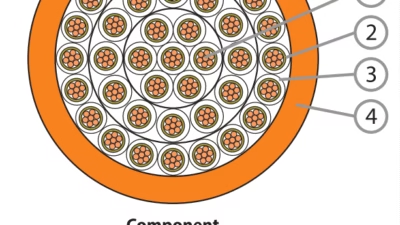
The construction of DIN VDE standard cables follows a precise layered architecture, with each component serving specific electrical, mechanical, and environmental protection functions. Understanding this structure is essential for proper cable selection and application.
Typical Construction Layers (from inner to outer)
1. Conductor
- Copper: Class 1 (solid) or Class 2 (stranded) per IEC 60228
- Aluminum: Always stranded for flexibility
- Compaction: Optional mechanical compression reducing diameter by 8-12%
- Standards: Conductivity ≥58 MS/m (copper), ≥35.5 MS/m (aluminum)
2. Conductor Screen (MV/HV)
- Semi-conductive layer: Smooths electrical field distribution
- Material: Extruded cross-linked PE with conductive carbon black
- Thickness: Typically 0.5-1.5 mm depending on voltage
- Function: Prevents partial discharge and corona effects
3. Insulation
- XLPE: Most common for MV cables; dielectric constant εr = 2.3
- PVC: Cost-effective for LV applications; εr = 4-8
- PE: Excellent electrical properties; εr = 2.2-2.3
- Thickness: Calculated per DIN VDE 0276 based on voltage class
4. Insulation Screen (MV/HV)
- Semi-conductive layer: Controls electric field at insulation surface
- Strippability: Must be easily removable for terminations
- Swelling tape: Optional water-blocking component
- Function: Provides equipotential surface for metallic screen
5. Metallic Screen
- Copper wires: Typically 16-50% of phase conductor area
- Copper tape: Longitudinal or helically applied
- Functions: Electromagnetic shielding, fault current path, neutral conductor
- Design: Per IEC 60502 screening requirements
6. Separation/Bedding
- Material: Non-hygroscopic tape or extruded layer
- Purpose: Separates metallic components from outer sheath
- Water blocking: Swelling powder or tape for (F) designation
- Thickness: Typically 0.5-2 mm
7. Armor (when specified)
- Steel tape: 0.5-2 mm thickness, zinc coated
- Wire armor: Round or flat wires, galvanized
- Protection: Mechanical impact resistance ≥2 J/cm
- Applications: Direct burial, areas with mechanical hazards
8. Outer Sheath
- PVC: Standard protection, 1.8-3.5 mm thickness
- PE: Enhanced moisture/chemical resistance
- LSZH: Low smoke, halogen-free for fire safety
- Color: Black (UV-resistant) or colored as specified
Multi-Core Cable Assembly
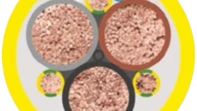
Multi-core cables incorporate additional construction elements to maintain structural integrity and electrical performance. Cores are typically arranged in a symmetrical pattern (triangular for 3-core, quadrant for 4-core), with fillers occupying interstitial spaces to create a circular overall geometry. A binding tape or extruded inner sheath holds the assembly together. For cables with individual core screens (designation SE or CE), each core receives its own metallic screen before assembly, providing superior electromagnetic isolation between phases.
Critical Construction Parameters
The thickness of insulation and screens is precisely calculated according to voltage class and follows the formula specified in DIN VDE 0276. For XLPE-insulated cables at 6/10 kV, the minimum insulation thickness is 3.4 mm for conductor sizes up to 300 mm². This increases to 5.5 mm for 12/20 kV applications and 8.0 mm for 18/30 kV systems. These dimensions ensure adequate dielectric strength with appropriate safety margins. The VDE Institute conducts rigorous testing to verify these parameters, including high voltage testing at 2.5 times the rated voltage plus 2 kV, applied for 15 minutes without breakdown. Such testing protocols are essential for ensuring cable safety and reliability in service.
Material Properties Comparison
| Property | XLPE | PVC | PE | LSZH (Halogen-Free) |
|---|---|---|---|---|
| Dielectric Constant (εr) | 2.3 | 4.0-8.0 | 2.2-2.3 | 3.0-3.5 |
| Dielectric Strength (kV/mm) | 20-25 | 15-20 | 20-25 | 18-22 |
| Volume Resistivity (Ω·m) | 10¹⁶ | 10¹³-10¹⁴ | 10¹⁶ | 10¹⁴-10¹⁵ |
| Dissipation Factor (tan δ) | <0.001 | 0.05-0.15 | <0.0005 | 0.005-0.02 |
| Thermal Conductivity (W/m·K) | 0.38-0.42 | 0.14-0.17 | 0.35-0.40 | 0.20-0.25 |
| Water Absorption (%) | <0.01 | 0.1-0.4 | <0.01 | 0.05-0.2 |
| Flame Propagation | Self-extinguishing | Self-extinguishing (formulated) | Burns | Self-extinguishing |
| Smoke Emission | Moderate | High | High | Very Low (<50% per IEC 61034) |
| Halogen Content | None | High (chlorine) | None | None (<0.5% per IEC 60754) |
| UV Resistance | Poor (requires protection) | Good (with stabilizers) | Good (with carbon black) | Varies (formulation dependent) |
6. Applications and Use Cases
DIN VDE standard cables serve diverse applications across industrial, commercial, utility, and specialized sectors. The comprehensive voltage range and construction options enable optimized solutions for virtually any power distribution requirement.
Low Voltage Applications (0.6/1 kV)
Building Installations
NYY and NAYY cables are extensively used in residential and commercial buildings for main distribution, sub-distribution, and final circuits. These cables provide reliable power delivery for lighting, heating, ventilation, and general-purpose receptacles. The PVC or PE sheath offers protection against mechanical damage and moisture intrusion. For applications requiring enhanced fire safety, such as high-rise buildings, escape routes, and public assembly spaces, halogen-free variants (N2XH, NYM-O) are specified to minimize smoke generation and toxic gas release in fire scenarios.
Industrial Machinery and Equipment
Fixed installation cables power motors, pumps, conveyors, and process equipment throughout manufacturing facilities. The robust construction withstands the mechanical stresses and environmental conditions typical of industrial settings, including exposure to oils, chemicals, and temperature variations. For applications involving frequent movement, such as crane systems and material handling equipment, specialized reeling cables designed for dynamic applications provide enhanced flexibility and mechanical endurance. These cables are engineered to withstand constant bending and flexing cycles while maintaining electrical integrity.
Medium Voltage Applications (6/10 kV to 18/30 kV)
Utility Distribution Networks
XLPE-insulated medium voltage cables form the backbone of urban and suburban electrical distribution systems. These cables connect primary substations to secondary distribution points, feeding residential neighborhoods, commercial districts, and light industrial areas. The compact design of XLPE cables compared to paper-insulated alternatives enables installation in congested underground duct systems. The longitudinally watertight construction (F designation) prevents water migration in buried applications, ensuring long-term reliability. Typical installations include direct burial, installation in concrete ducts, and laying in cable trenches with additional mechanical protection.
Industrial Plants and Heavy Manufacturing
Large industrial facilities require medium voltage distribution to efficiently transmit power from utility connection points to various plant sections. Steel mills, chemical plants, automotive manufacturing, and similar facilities operate at 10-20 kV distribution voltages to minimize transmission losses over large campus-style installations. Cables with individual core screening (designation SE) provide electromagnetic compatibility in environments with significant electrical noise from variable frequency drives, arc furnaces, and other high-power electronic equipment. For facilities in the mining sector, specialized mining cables meeting AS/NZS standards offer additional mechanical protection and chemical resistance for harsh underground environments.
Renewable Energy Installations
Wind farms and solar parks utilize DIN VDE cables for collector systems that aggregate power from individual generating units. Wind turbine tower cables operate under particularly demanding conditions, subjected to continuous flexing from tower oscillations and nacelle rotation. These applications require cables with enhanced mechanical properties and resistance to lubricants commonly present in wind turbine environments. Solar installations employ UV-resistant sheaths (black PE with carbon black additive) to withstand prolonged outdoor exposure without degradation.
Special Applications
Power Plants and Generation Facilities
Nuclear, fossil fuel, and combined cycle power plants demand the highest reliability and fire safety performance. Cables in these facilities must maintain circuit integrity during fire events to ensure safe plant shutdown. DIN VDE 0273 specifies requirements for cables with improved fire characteristics, including halogen-free insulation and sheathing materials. These cables undergo rigorous testing according to IEC 60332 for flame propagation and IEC 61034 for smoke density, ensuring they meet stringent safety criteria. Additionally, cables for containment penetrations in nuclear facilities must demonstrate radiation resistance and maintain insulation integrity under elevated radiation fields.
Transportation Infrastructure
Railway electrification systems, metro transit networks, and airport facilities specify DIN VDE cables for power distribution and signaling applications. These installations require cables resistant to vibration, mechanical stress, and environmental extremes. Tunnels and underground stations necessitate low-smoke, halogen-free cables to protect evacuating passengers and emergency responders in fire events. The reduced smoke production and non-corrosive combustion products of LSZH cables (per IEC 60754 with halogen content <0.5%) are critical safety features in these enclosed spaces.
Application Selection Considerations
Proper cable selection requires comprehensive analysis of operational requirements, environmental conditions, and regulatory compliance. Key factors include continuous and emergency current requirements, short circuit capacity, voltage drop calculations, ambient and conductor temperatures, installation method (direct burial, ducts, trays, ladder), grouping and derating factors, mechanical protection requirements (armoring needs), environmental exposures (chemicals, moisture, UV), fire safety regulations (smoke and toxicity limits), electromagnetic compatibility requirements, and expected service life and maintenance accessibility. Cable sizing calculations must account for all derating factors per DIN VDE 0298-4, including ambient temperature correction, grouping factors for multiple circuits, and soil thermal resistivity for buried installations.
7. Safety Standards and Compliance Requirements
DIN VDE standards incorporate comprehensive safety requirements covering electrical performance, fire resistance, mechanical integrity, and environmental protection. Compliance verification involves extensive testing protocols conducted by accredited laboratories, with the VDE certification mark serving as recognized proof of conformity.
Electrical Safety Testing
| Test Parameter | Standard | Requirement | Test Duration |
|---|---|---|---|
| High Voltage Test (AC) | DIN VDE 0472-804 | 2.5 x Uo + 2 kV | 15 minutes |
| Partial Discharge Test | IEC 60502-4 | <10 pC at 1.5 x Uo | Continuous during voltage test |
| Insulation Resistance | DIN VDE 0472-509 | >50 GΩ·km at 20°C | 1 minute at 500V DC |
| Hot Set Test | DIN VDE 0472-603 | Elongation <175% (XLPE) | 15 minutes at 200°C under load |
| Impulse Voltage Test | IEC 60230 | 1.2/50 μs wave, 75 kV (10 kV cable) | 10 positive + 10 negative impulses |
| Load Cycling Test | IEC 60502-2 | 20 cycles, 8h heating/16h cooling | 480 hours total |
Fire Performance Requirements
Fire safety represents a critical aspect of cable performance, particularly in applications where cable failure could endanger life or critical infrastructure. Testing laboratories affiliated with the VDE Institute conduct comprehensive fire performance evaluations to verify compliance with applicable standards. These tests assess multiple aspects of fire behavior, including flame propagation characteristics, smoke generation rates, toxic gas emissions, and circuit integrity maintenance under fire conditions.
| Fire Test | Standard | Pass Criteria | Application |
|---|---|---|---|
| Single Cable Vertical Flame Test | IEC 60332-1-2 / VDE 0482-332-1-2 | Char length <540 mm; self-extinguishing within 60s | General purpose installations |
| Bundled Cable Flame Propagation | IEC 60332-3-24 / VDE 0482-332-3-24 | Total carbonized length <2.5m for Category C | Vertical cable runs in buildings |
| Smoke Density | IEC 61034 / VDE 0482-1034 | Light transmission ≥60% for LSZH cables | Enclosed spaces, tunnels, ships |
| Halogen Gas Content | IEC 60754-1 / VDE 0482-754-1 | <0.5% halogen content (HF equivalent) | Low smoke halogen-free applications |
| Gas Acidity (pH) | IEC 60754-2 / VDE 0482-754-2 | pH ≥4.3, conductivity <10 μS/mm | Equipment rooms, control centers |
| Circuit Integrity | IEC 60331 / VDE 0482-331 | Maintain function for 90-180 minutes at 830°C | Fire alarm, emergency lighting |
| Fire Resistance CPR | EN 50399 | Class B2ca for standard installations | European Construction Products Regulation |
VDE Certification Process
VDE certification provides third-party verification of cable performance and safety. The certification process involves initial type testing of cable samples, factory production control audits, ongoing surveillance testing of production cables, and periodic re-certification. The VDE Institute, headquartered in Frankfurt, operates as one of Europe’s most respected testing and certification organizations. Cables bearing the VDE mark have undergone rigorous evaluation confirming compliance with applicable standards. Independent laboratory testing validates electrical properties, mechanical strength, fire performance, and environmental resistance. The comprehensive testing protocols ensure cables meet strict safety criteria and perform reliably throughout their service life. Regular market surveillance by VDE maintains the integrity of the certification program.
Mechanical and Environmental Testing
| Test Type | Standard | Specification | Purpose |
|---|---|---|---|
| Tensile Strength | DIN VDE 0472-603 | >12.5 MPa (XLPE); >15 MPa (PVC) | Verify mechanical integrity |
| Elongation at Break | DIN VDE 0472-603 | >200% (XLPE); >150% (PVC) | Assess material flexibility |
| Impact Resistance | DIN VDE 0472-506 | No cracks at 2 J impact (armored cables) | Validate protection against mechanical damage |
| Cold Bend Test | DIN VDE 0472-604 | No cracking at -25°C (XLPE); -5°C (PVC) | Ensure low temperature flexibility |
| Thermal Aging | DIN VDE 0472-814 | Maintain 60% of initial properties after aging | Predict long-term service life |
| Water Penetration | IEC 60502-4 | No water ingress over 1m length in 24h | Verify longitudinal watertightness |
| Ozone Resistance | DIN VDE 0472-805 | No cracks after 24h exposure at 40°C | Assess environmental durability |
Electromagnetic Compatibility (EMC)
Proper cable design and installation are essential for electromagnetic compatibility in modern electrical systems. Screened cables (S, SE designations) provide electromagnetic shielding that attenuates both conducted and radiated emissions. The screen effectiveness depends on the screen construction, with copper wire braids offering coverage typically exceeding 85-95%. For maximum EMC performance, cables with individual core screening (SE designation) provide isolation between phases. Proper earthing of cable screens at both ends ensures effective electromagnetic shielding while providing a path for induced currents and fault currents.
Regulatory Compliance Requirements
Cable installations must comply with multiple regulatory frameworks beyond DIN VDE standards. The European Construction Products Regulation (CPR) mandates fire performance classification for cables installed in buildings, with requirements specified in EN 50575. Cables must be classified according to fire performance from Class Aca (highest performance) to Class Fca (no performance determined). Industrial installations must comply with workplace safety regulations, while specialized environments such as explosive atmospheres require compliance with ATEX directives and IEC 60079 standards. Medical facilities follow DIN VDE 0107 for electrical installations in hospitals. Nuclear installations adhere to KTA standards and IEEE nuclear qualification protocols. These overlapping requirements necessitate careful specification and documentation during project planning phases.
8. Installation Guidelines and Precautions
Proper installation practices are critical for ensuring cables achieve their design performance and service life. The following guidelines cover essential considerations for handling, installing, and protecting DIN VDE cables in various applications.
Pre-Installation Considerations
Cable Storage
- Store drums on level ground preventing deformation
- Protect from direct sunlight, rain, and temperature extremes
- Maximum storage temperature: 40°C for XLPE, 35°C for PVC
- Minimum storage temperature: -25°C; warm before installation if colder
- Keep drums covered with tarpaulins or similar protection
- Inspect drum and cable end seals before installation
Installation Temperature Limits
- XLPE insulated cables: minimum -20°C without pre-warming
- PVC insulated cables: minimum -5°C; warm to +15°C if colder
- PE sheathed cables: minimum -40°C with appropriate handling
- Cold cables become brittle and susceptible to cracking
- Gradual warming required; never use open flames or direct heat
- Allow adequate time for thermal equilibration before pulling
Bending Radius Requirements
- Unarmored MV cables: 15 x overall diameter during installation
- Armored cables: 20 x overall diameter during installation
- Fixed installation minimum: 12 x diameter (unarmored)
- Fixed installation minimum: 15 x diameter (armored)
- Single-core cables with metallic screens require larger radii
- Exceeding limits damages insulation and screens permanently
Pulling Tensions
- Copper conductors: maximum 50 N/mm² of conductor area
- Aluminum conductors: maximum 30 N/mm² of conductor area
- Use pulling grips or pulling stockings, never bare conductor
- Install tension monitoring equipment for long pulls
- Apply lubricants approved for cable jacket material
- Avoid sidewall pressure exceeding 500 N/m in conduits
Installation Methods
Direct Burial Installation
Direct burial remains a common installation method for power distribution cables. Proper installation requires excavating trenches to minimum depths prescribed by local codes, typically 0.8-1.0 meters for MV cables. The trench bottom must be prepared with a sand or fine soil bedding layer of at least 100 mm depth, free from stones and sharp objects. Cables are laid without tension, allowing natural expansion/contraction. A protective covering of sand or fine soil (minimum 150 mm) is placed above cables before backfilling. Mechanical protection using cable tiles, concrete slabs, or warning tape is installed 300 mm above cables. For areas subject to vehicular traffic or excavation activity, armored cables (designation B, F, G, or R) provide essential mechanical protection. Multiple cables in the same trench must be separated by at least one cable diameter or 150 mm, whichever is greater, to ensure adequate heat dissipation.
Duct and Conduit Installation
Installation in ducts or conduits protects cables from mechanical damage and facilitates future replacement. Duct sizing must provide adequate space for cable installation and heat dissipation. The maximum fill ratio should not exceed 40% of duct internal cross-sectional area for multiple cables, or 53% for single cables. Appropriate lubricants reduce pulling friction and prevent jacket damage. For MV cables, duct systems should be sized to accommodate cables with adequate air space for cooling. Manholes and pulling vaults must be strategically located to limit pulling lengths and provide access for splicing. Typical maximum straight pull distances range from 150-300 meters depending on cable size, duct configuration, and available pulling equipment. Cables should be secured at intervals not exceeding 1.5 meters in vertical sections to prevent conductor elongation.
Cable Tray and Ladder Installation
Tray installations offer easy access for inspection and simplified installation. Cables must be secured at regular intervals using appropriate fixing devices that distribute clamping forces without deforming cables. Maximum securing intervals: 0.5 meters for vertical runs, 1.0 meters for horizontal runs. Multi-core cables should be laid in a single layer wherever practical to optimize heat dissipation. Single-core cables of three-phase circuits must be installed in trefoil formation or triangular configuration to minimize circulating currents in metallic screens and sheaths. For armored single-core cables, screen and armor should be bonded at one end only unless special bonding systems are implemented. Adequate clearances between trays and building structure ensure proper ventilation and prevent heat accumulation.
Termination and Jointing
Critical Installation Requirements for Medium Voltage Cables
Medium voltage cable terminations and joints require meticulous installation procedures to ensure reliable long-term performance. All work must be performed in clean, dry conditions by trained personnel using manufacturer-approved materials and procedures. The semi-conductive screens must be removed precisely to dimensions specified by the termination kit manufacturer. Any contamination of the insulation surface with semi-conductive material, dirt, or moisture leads to tracking failure. Stress control is achieved using geometric stress cones or electric stress control materials that properly control the electric field where the cable screen terminates. Proper pressure and contact resistance at the conductor connection prevent hot spots that degrade insulation. All interfaces between components must be void-free to eliminate partial discharge initiation sites. Installation records documenting materials, procedures, and environmental conditions provide valuable information for troubleshooting and maintenance planning.
Grounding and Bonding
Proper grounding and bonding of cable metallic screens and armor is essential for safety and performance. For single-point bonded systems, screens are bonded to earth at one location only, typically the source end. This arrangement minimizes circulating currents in the screen under normal operation but requires screen voltage limiters at the ungrounded end to prevent dangerous voltages during fault conditions. Multi-point bonding systems connect screens to earth at multiple locations along the route, limiting screen voltages but inducing circulating currents that reduce cable current-carrying capacity. The choice between bonding methods depends on route length, fault current levels, and economic considerations. Cross-bonding systems divide routes into major sections with screens transposed at section joints, balancing induced voltages and minimizing screen losses. All bonding connections must be mechanically and electrically sound, with corrosion-resistant materials used in aggressive environments.
9. Common Problems and Solutions
Installation-Related Issues
| Problem | Symptoms | Causes | Solutions/Prevention |
|---|---|---|---|
| Insulation Damage During Installation | Visible cuts, abrasions, or punctures; dielectric failure after energization | Excessive pulling tension; sharp edges in ducts; improper handling; insufficient bending radius | Use cable rollers at duct entries; inspect route for sharp edges; monitor pulling tension; train installers on proper handling; replace damaged sections |
| Screen/Shield Damage | Broken screen wires; compromised electromagnetic shielding; ground fault detection issues | Over-tightening of cable cleats; excessive bending; improper handling during uncoiling | Use appropriate securing devices; maintain minimum bending radii; carefully inspect screens before termination; test screen continuity |
| Water Ingress at Cable Ends | Moisture in terminations; reduced insulation resistance; tracking and flashover | Inadequate end sealing; damaged outer sheath; condensation in termination area | Apply proper cable end caps during storage; use heat-shrink or cold-applied seals; maintain dry conditions during termination; test insulation resistance before energization |
| Thermal Overload | Elevated conductor temperature; insulation degradation; premature aging | Undersized cable selection; excessive loading; inadequate heat dissipation; incorrect derating factors | Verify load calculations including all derating factors; ensure proper installation spacing; improve ventilation in congested areas; monitor temperatures with permanent instrumentation |
In-Service Failures
| Failure Mode | Typical Causes | Diagnostic Methods | Mitigation Strategies |
|---|---|---|---|
| Partial Discharge | Voids in insulation; contaminated surfaces; poor termination quality; water treeing in aged cables | Partial discharge testing (online or offline); dissipation factor testing; cable condition assessment | Regular condition monitoring; timely replacement of aged cables; quality control during installation; rejuvenation treatments for aged cables |
| Tracking and Flashover | Surface contamination; moisture ingress; damaged terminations; aged components | Visual inspection; infrared thermography; insulation resistance testing; hi-pot testing | Regular cleaning of outdoor terminations; replacement of damaged components; environmental sealing; application of tracking-resistant materials |
| Mechanical Damage | External excavation; ground movement; inadequate protection; rodent attack | Time domain reflectometry (TDR); route inspection; records review | Accurate cable route documentation; marking and warning systems; adequate burial depth; physical barriers in rodent-prone areas |
| Corrosion of Metallic Components | Electrochemical corrosion; stray currents; galvanic action; aggressive soil conditions | Continuity testing of screens; corrosion monitoring; soil resistivity measurements | Proper bonding design; cathodic protection systems; corrosion-resistant materials; soil treatment in aggressive environments |
| Joint/Termination Failure | Poor workmanship; material degradation; electrical stress concentration; thermal cycling | Thermographic inspection; partial discharge detection; tan delta measurements | Use qualified installers; follow manufacturer procedures exactly; regular inspection and maintenance; timely replacement of aged accessories |
Environmental Degradation
Water Treeing in XLPE Cables
Water treeing represents a degradation mechanism in XLPE insulation exposed to moisture over extended periods. Microscopic tree-like structures form in the insulation, gradually reducing dielectric strength. This phenomenon primarily affects cables installed in wet environments or with compromised water barriers. Modern XLPE formulations incorporate water tree retardant additives significantly reducing susceptibility. For existing cables exhibiting water tree degradation, rejuvenation treatments involving injection of dielectric enhancement fluids may extend service life. Preventive measures include longitudinally watertight construction (F designation), proper end sealing, and specification of water tree-resistant XLPE (TR-XLPE) for wet applications.
UV Degradation of Cable Jackets
Prolonged exposure to ultraviolet radiation causes degradation of polymer sheaths, particularly PE and some PVC formulations. Surface cracking, chalking, and loss of mechanical properties indicate UV damage. Prevention requires using cables with UV-stabilized sheaths for outdoor applications. Black-colored sheaths incorporating carbon black provide inherent UV protection. For aerial installations or temporary outdoor use, UV-protective wraps or conduit housing prevent direct exposure. Regular inspection of outdoor cable sections identifies early signs of degradation enabling timely protective measures.
Preventive Maintenance Programs
Systematic preventive maintenance significantly extends cable system life and reduces failure incidents. Recommended programs include annual visual inspection of accessible cable sections, terminations, and joints; biennial thermographic surveys identifying hot spots indicating poor connections or overloading; triennial insulation resistance testing establishing baseline trends; and periodic partial discharge testing of critical MV cables identifying incipient failures before catastrophic breakdown. Documentation of inspection findings and test results enables trend analysis and predictive maintenance. Maintenance intervals should be adjusted based on operating environment severity, criticality of circuits, and observed condition trends. For critical infrastructure applications, condition-based monitoring provides real-time assessment enabling proactive intervention.
10. Maintenance and Testing Protocols
Systematic maintenance and testing ensure cables continue performing safely and reliably throughout their service life. Testing protocols established in DIN VDE standards provide frameworks for condition assessment and acceptance testing.
Routine Inspection Procedures
| Inspection Type | Frequency | Key Points | Documentation |
|---|---|---|---|
| Visual Inspection | Annually | Check for physical damage, deformation, discoloration, moisture ingress, pest intrusion, support integrity | Photo documentation of anomalies; location sketches; condition rating system |
| Thermal Imaging | Biennially | Scan terminations and joints; identify hot spots; compare to baseline temperatures; trend analysis | Thermograms with temperature annotations; comparison to previous surveys; prioritized action list |
| Load Monitoring | Continuous or Monthly | Verify loading within design limits; identify overload conditions; balance phase loading | Load profiles; peak demand records; comparison to cable ratings |
| Route Inspection | After Ground Disturbance | Verify route markers intact; check for unauthorized excavation; inspect protection systems | Route verification records; photographic evidence; notification to relevant parties |
Electrical Testing Methods
Insulation Resistance Testing
Insulation resistance measurement provides a fundamental assessment of cable condition. Testing applies DC voltage between conductors and between conductors and earth, measuring resulting leakage current. For cables rated 0.6/1 kV, test voltage is typically 500-1000 VDC; for MV cables, test voltage is normally 2.5 kV DC or higher based on voltage class. Minimum acceptable resistance values depend on cable length and construction, but generally should exceed 1000 MΩ·km for new installations. Progressive degradation indicated by declining resistance values suggests moisture ingress or insulation deterioration. Testing should be performed under controlled temperature conditions as insulation resistance varies significantly with temperature. Results are temperature-corrected to standard reference temperature (typically 20°C) for valid trend comparison.
Very Low Frequency (VLF) Testing
VLF testing applies AC voltage at frequencies of 0.1 Hz or lower, providing more realistic stress of cable insulation compared to DC testing. VLF effectively detects defects while minimizing space charge accumulation. Test voltages follow standards such as IEEE 400.2, typically applying 2.0 times operating voltage for maintenance testing or 3.0 times for acceptance testing. During testing, partial discharge measurements can be performed simultaneously, providing enhanced diagnostic capability. Tan delta measurements during VLF testing identify localized degradation not evident through voltage withstand alone. Modern VLF test equipment incorporates diagnostic features including tan delta trending, partial discharge monitoring, and voltage ramping protocols. This method has become preferred for MV cable testing due to its effectiveness and safety compared to traditional DC hi-pot testing.
Partial Discharge Testing
Partial discharge (PD) detection identifies localized insulation defects before they propagate to complete failure. PD testing can be performed offline during maintenance outages or online during normal operation using specialized sensors. Offline PD testing typically utilizes VLF voltage or resonant test systems. Online PD monitoring employs capacitive couplers, high-frequency current transformers (HFCTs), or transient earth voltage (TEV) sensors. Interpretation of PD patterns requires expertise, with different defect types producing characteristic signatures. Common PD sources include voids in insulation, contamination at terminations, poor workmanship in accessories, and water treeing in aged cables. Regular PD testing establishes baseline signatures enabling detection of emerging problems through trend analysis. For critical circuits, permanent online PD monitoring provides continuous surveillance and automated alarming of significant changes.
Testing After Installation
Commissioning Test Sequence
New cable installations require comprehensive testing before energization to verify installation quality and establish baseline data. The typical test sequence includes continuity testing of conductors and screens, insulation resistance measurement between conductors and to earth, high voltage testing per voltage class requirements, phase identification and rotation verification, bonding and earthing continuity confirmation, and protective relay function testing. For MV cables, additional tests include partial discharge measurement, tan delta testing, and VLF withstand testing. All test results must be documented with cable identification, test parameters, ambient conditions, and pass/fail determination. These commissioning records provide invaluable baseline data for future condition assessments. Any test failures require investigation, remediation, and retesting before the cable is placed in service.
Testing Standards and Procedures
| Test Standard | Application | Key Parameters | Acceptance Criteria |
|---|---|---|---|
| DIN VDE 0101 | Power installations acceptance | Insulation resistance, voltage withstand, protective conductor continuity | As specified in standard for voltage class |
| IEEE 400-2001 | Field testing of shielded power cables | DC hi-pot, VLF testing protocols | No breakdown at test voltage; insulation resistance within limits |
| IEEE 400.2-2013 | VLF and tan delta testing | Test voltage levels, duration, acceptance limits for tan delta | Tan delta <specified limits based on voltage class and age |
| IEC 60502-4 | Routine and type testing | Electrical, thermal, mechanical tests per cable type | Compliance with all specified tests |
Safety Precautions During Testing
High voltage testing presents serious safety hazards requiring strict adherence to safety protocols. All personnel must be trained and qualified for high voltage work per DIN VDE 0105. Test areas must be secured with barriers and warning signs preventing unauthorized access. Cables must be disconnected from all sources of voltage and verified de-energized before connecting test equipment. Proper discharge procedures must be followed after testing, allowing sufficient time for capacitive energy dissipation. Test equipment must be properly grounded and operated according to manufacturer instructions. Personal protective equipment including voltage-rated gloves, safety glasses, and arc-rated clothing should be used as appropriate for the test voltage level. Emergency response procedures must be established and communicated to all test personnel. Only qualified persons may perform testing, with a safety watch person present during high voltage application. These precautions protect personnel and prevent equipment damage during testing operations.
Authoritative References and Standards
- VDE Association for Electrical, Electronic & Information Technologies – Official standards development and testing organization
- DIN VDE Cable Standards Overview – Comprehensive guide to VDE cable standards and specifications
- CableDataSheet Technical Consulting – Technical information on DIN VDE cable designation systems
- Bayerische Kabelwerke Type Designation Codes – Detailed cable coding systems per DIN VDE standards
- Power Cable Standards Reference – International cable standards including DIN VDE specifications