Comprehensive Technical Guide to Industrial Power Distribution Cables
What is UNE 21123 Standard Cable?
Comprehensive Technical Guide to Industrial Power Distribution Cables
UNE 21123 is a Spanish electrical cable standard developed by AENOR (Asociación Española de Normalización y Certificación), the Spanish Association for Standardisation and Certification. This standard specifies the design, construction, and cross-sectional area requirements for cables used in power distribution circuits with voltage ratings up to and including 600/1000V (0.6/1 kV).[1]
As a member of ISO, IEC, and CENELEC, AENOR develops standards in conjunction with European and international conventions, ensuring that UNE 21123 cables meet both regional and global safety and performance requirements.[2] These cables are widely used in transmission, distribution, and power networks across industrial installations in Europe and beyond.
1. Purpose and Applications of UNE 21123 Cables
UNE 21123 cables are designed specifically for industrial electrical installations operating at rated voltages of 0.6/1 kV. The standard establishes construction requirements, dimensional specifications, and testing protocols to ensure reliable performance in demanding environments.[3]
Primary Applications
Power Distribution Networks
Fixed wiring installations for electricity transmission and distribution in utility networks and industrial facilities.
Underground Installations
Cable ducting and direct burial applications requiring mechanical protection from steel wire armour.
Indoor Applications
Internal building installations where fire safety is critical, particularly with LSZH (Low Smoke Zero Halogen) polyolefin sheathed variants.
Oil & Gas Industry
Specialized applications in petrochemical facilities, with UNE 21123-5 (EPR insulated cables) being particularly prevalent.[4]
2. Construction and Material Structure
The UNE 21123 standard comprises five distinct sub-sections, each specifying different insulation and sheathing material combinations to suit various installation environments and performance requirements.
2.1 Standard Sub-sections
| Standard | Insulation Material | Sheath Material | Primary Application |
|---|---|---|---|
| UNE 21123-1 | PVC (Polyvinyl Chloride) | PVC | External installations, cost-effective general wiring |
| UNE 21123-2 | XLPE (Cross-linked Polyethylene) | PVC | Enhanced thermal performance, distribution networks |
| UNE 21123-3 | EPR (Ethylene Propylene Rubber) | PVC | Flexible installations, dynamic environments |
| UNE 21123-4 | XLPE | Polyolefin (LSZH) | Fire-sensitive areas, internal applications |
| UNE 21123-5 | EPR (HEPR – High Modulus) | Polyolefin (LSZH) | Oil & gas, hazardous environments[5] |
2.2 Detailed Construction Layers
Using the RZ1MZ1-K cable (UNE 21123-4 compliant) as a reference example, the typical construction from inner to outer layers consists of:
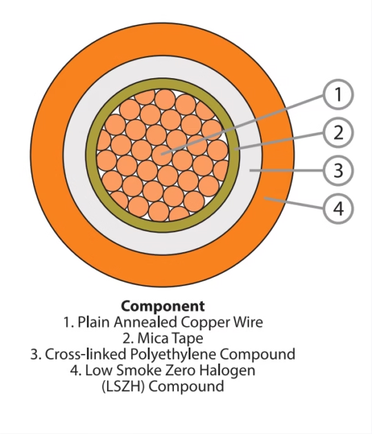
- Conductor: Class 5 flexible copper conductor complying with EN 60228 standard. Conductors are stranded and may be plain or tinned copper, providing excellent conductivity and flexibility.
- Insulation: XLPE (Cross-Linked Polyethylene) provides superior dielectric strength, thermal stability up to 90°C continuous operation, and resistance to moisture and chemicals.[6]
- Bedding Layer: LSZH compound separates the insulated cores from the armour, providing additional mechanical protection.
- Armour: Galvanized steel wire armour (SWA) for multicore cables, offering mechanical protection against crushing, impact, and rodent damage in underground installations.
- Outer Sheath: LSZH (Low Smoke Zero Halogen) polyolefin compound providing fire safety characteristics including reduced flame spread, minimal smoke emission, and halogen-free gas emission.[7]
2.3 Core Identification Standards
Core identification follows standardized color coding schemes to ensure safe installation and maintenance:
| Number of Cores | Color Identification |
|---|---|
| 1 core | Black |
| 2 core | Blue, Brown |
| 3 core | Grey, Black, Brown |
| 3 core + earth | Green/Yellow, Blue, Brown |
| 4 core | Blue, Brown, Black, Grey |
| 4 core + earth | Green/Yellow, Brown, Black, Grey |
| 5 core + earth | Green/Yellow, Blue, Brown, Black, Grey |
Outer sheath color is typically green for armoured LSZH cables.
3. Technical Characteristics and Performance Parameters
3.1 Electrical Ratings
Voltage Rating (U₀/U)
0.6/1 kV – where U₀ is the rated voltage between conductor and earth, and U is the rated voltage between conductors
Temperature Rating
Normal Operation: -40°C to +90°C
Short Circuit (≤5s): 250°C maximum for XLPE/EPR
Frequency
50 Hz AC systems (standard European frequency)
Conductor Material
Copper: Class 5 flexible stranded conductor per EN 60228
3.2 Current Carrying Capacity and Voltage Drop
The current carrying capacity varies significantly based on installation method, ambient temperature, and number of cores. The following table presents representative data for UNE 21123-4 compliant cables:
| Cross-Section (mm²) | In Air 40°C 2 Core (A) | In Ground 25°C 2 Core (A) | In Air 40°C 3-5 Core (A) | Voltage Drop cos φ=0.8 (V/A/km) |
|---|---|---|---|---|
| 1.5 | 24 | 27 | 20 | 23.61 |
| 2.5 | 33 | 36 | 26 | 14.20 |
| 6 | 57 | 58 | 46 | 5.92 |
| 10 | 79 | 77 | 65 | 3.46 |
| 16 | 105 | 100 | 87 | 2.22 |
| 25 | 123 | 128 | 110 | 1.46 |
| 50 | 188 | 183 | 167 | 0.76 |
| 95 | 296 | 265 | 259 | 0.44 |
| 185 | 464 | 383 | 391 | 0.26 |
| 240 | 552 | 442 | 468 | 0.22 |
Current carrying capacities are provided for guidance and may vary based on specific installation conditions. Voltage drop values are for power factor (cos φ) of 0.8.
3.3 Conductor Resistance
Maximum conductor resistance at 20°C according to EN 60228:
| Nominal Cross-Section (mm²) | Maximum Resistance at 20°C (Ω/km) | Maximum Wire Diameter (mm) |
|---|---|---|
| 1.5 | 13.30 | 0.26 |
| 2.5 | 7.98 | 0.26 |
| 4 | 4.95 | 0.31 |
| 6 | 3.30 | 0.31 |
| 10 | 1.91 | 0.41 |
| 16 | 1.21 | 0.41 |
| 25 | 0.78 | 0.41 |
| 50 | 0.386 | 0.41 |
| 95 | 0.206 | 0.51 |
| 185 | 0.106 | 0.51 |
| 240 | 0.0801 | 0.51 |
4. Standards Compliance and Certifications
UNE 21123 cables must comply with multiple international and European standards to ensure safety, performance, and interoperability. Compliance with these standards is verified through rigorous type testing and routine production testing.
4.1 Primary Standards
UNE 21123 Series: Core Spanish standard defining construction and testing requirements for industrial cables rated 0.6/1 kV.
IEC 60502-1: International standard for power cables with extruded insulation for rated voltages of 1 kV. Specifies requirements for XLPE and EPR insulation materials, including thermal properties and dielectric strength.[8]
EN 60228: European standard specifying conductor classes, materials (copper or aluminum), stranding configurations, and maximum resistance values.
HD 603: Harmonized European document for distribution cables rated 0.6/1 kV, ensuring compatibility across European markets.
4.2 Fire Performance Standards
LSZH variants of UNE 21123 cables undergo comprehensive fire testing to meet stringent safety requirements, particularly important for installations in enclosed spaces, public buildings, and critical infrastructure:
| Standard | Test Description | Performance Requirement |
|---|---|---|
| IEC 60332-1 | Vertical flame propagation test for single cables | Cable must self-extinguish and limit flame spread to specified length[9] |
| IEC 60332-3 | Flame propagation test for bundled cables | Prevents fire spread in cable bundles and vertical installations |
| IEC 60754-1/2 | Halogen acid gas emission during combustion | pH ≥ 4.3, conductivity ≤ 10 μS/mm (ensures zero halogen emission)[10] |
| IEC 61034-1/2 | Smoke density measurement (3m³ cube test) | Light transmittance must remain above minimum threshold to ensure visibility during evacuation[11] |
| EN 50575 | EU Construction Products Regulation (CPR) | Classification of reaction to fire properties for cables in construction works |
5. Safety Thresholds and Operating Limits
5.1 Temperature Limits
Critical Temperature Thresholds:
Normal Operation: Conductor temperature must not exceed 90°C for XLPE and EPR insulated cables during continuous operation. This limit is established based on the thermal aging characteristics of the insulation materials and ensures a minimum service life of 30 years under normal conditions.[12]
Short Circuit Conditions: During short circuit events lasting up to 5 seconds, the maximum permissible conductor temperature is 250°C for XLPE and HEPR insulation. This threshold prevents irreversible degradation of the cross-linked polymer structure.[13]
Minimum Installation Temperature: Cable installation should not be performed when the ambient temperature is below -5°C to prevent mechanical damage to the sheath and insulation during handling.
5.2 Mechanical Limits
| Parameter | Specification | Safety Consideration |
|---|---|---|
| Minimum Bending Radius | 12 × Overall Diameter (OD) for armoured cables 8 × OD for unarmoured cables | Prevents damage to conductor, insulation, and armour during installation |
| Maximum Pulling Tension | 50 N/mm² for copper conductors | Exceeding this limit may cause permanent conductor elongation |
| Radial Crushing Force | Steel wire armour provides protection up to 2,500 N for typical sizes | Essential for underground installations subject to soil pressure |
| Impact Resistance | LSZH sheath maintains integrity at -40°C | Low temperature impact performance critical for cold climate installations |
5.3 Electrical Safety Limits
Voltage Withstand Test: Cables must withstand a test voltage of 3.5 kV AC for 5 minutes between conductor and earth, and between conductors, without breakdown or partial discharge exceeding 10 pC. This test verifies insulation integrity and absence of manufacturing defects.
Insulation Resistance: Minimum insulation resistance of 0.02 MΩ·km at 20°C. For cables immersed in water for 1 hour, the minimum is 0.01 MΩ·km.
Partial Discharge: At 1.5 times rated voltage, partial discharge levels must not exceed 10 picocoulombs (pC) to ensure long-term reliability.[14]
6. Installation Precautions and Best Practices
6.1 Pre-Installation Considerations
Proper planning and preparation are essential for successful cable installation and long-term system reliability:
Cable Storage: Store cables in a dry, covered area away from direct sunlight. LSZH materials can degrade under prolonged UV exposure. Maintain storage temperature between -5°C and +35°C. Drum rotation should be minimized to prevent mechanical stress on the cable layers.
Inspection Before Installation: Conduct thorough visual inspection of drum and cable for transport damage. Check for sheath cuts, armor displacement, or end seal damage. Verify cable specifications match project requirements using the identification markings printed on the sheath.
Environmental Assessment: Evaluate installation route for potential hazards including chemical exposure, high temperatures, excessive vibration, or mechanical stress. Ensure cable rating exceeds anticipated thermal and electrical loads with appropriate derating factors applied.
6.2 Installation Guidelines
- Bending Radius Compliance: Never exceed minimum bending radius specifications. Use appropriate cable supports and guides, particularly at changes in direction. For armoured cables, this is typically 12 times the overall diameter.
- Pulling Tension Monitoring: Use calibrated pulling equipment with tension monitoring for long cable runs. Maximum pulling tension should not exceed 50 N/mm² of conductor cross-sectional area. Consider using pulling eyes attached to armour rather than conductor for very long pulls.
- Underground Installation: For direct burial, install cables at minimum depth of 600mm in areas without vehicle traffic, or 900mm under roadways. Use sand bedding above and below cable, avoiding stones that could damage the sheath. Install warning tape 300mm above cable route.
- Cable Support: For vertical installations, provide cable cleats or supports at maximum 1.5 meter intervals to prevent excessive stress on cable structure. Use non-metallic fixings for single-core cables to avoid circulating currents.
- Termination and Jointing: Use only approved cable accessories compliant with IEC 60502-4. Ensure termination glands maintain IP rating appropriate for installation environment. Strip cable layers to manufacturer’s specifications, avoiding damage to underlying layers.[15]
- Earth Continuity: For armoured cables, ensure proper electrical bonding of armor at both ends to maintain effective earth fault protection. Use appropriate armour clamps and ensure good electrical contact.
- Load Derating: Apply derating factors for grouped cables, elevated ambient temperatures, or thermal resistivity of soil exceeding 1.0 K·m/W. Consult IEC 60364-5-52 for specific derating calculations.
6.3 Testing After Installation
| Test | Method | Acceptance Criteria |
|---|---|---|
| Insulation Resistance | 500V DC megger for 1 minute | ≥ 100 MΩ at 20°C for complete installation |
| Continuity Test | Low resistance ohmmeter | Measured resistance within 5% of calculated value |
| Earth Continuity | Earth loop impedance tester | Armor bonding resistance < 0.5 Ω |
| Phasing | Phase rotation indicator | Correct phase sequence confirmed |
7. Common Problems and Troubleshooting
7.1 Installation-Related Issues
Problem: Sheath Damage During Installation
Cause: Exceeding minimum bending radius, dragging over sharp edges, or excessive pulling tension.
Solution: Immediately stop installation and assess damage extent. Minor abrasions may be repaired with approved repair tape if core integrity is unaffected. Major damage requires cable section replacement. Prevention includes using cable rollers, guide tubes, and proper training for installation crews.
Problem: Overheating During Operation
Cause: Undersized cable for load current, inadequate ventilation, grouping effects not considered, or higher-than-expected ambient temperature.
Solution: Measure actual operating temperature using thermal imaging. If temperature exceeds 90°C, immediately reduce load or improve cooling. Verify calculations included appropriate derating factors. May require cable replacement with larger size or installation of additional parallel circuits.[16]
7.2 Operational Issues
Problem: Premature Aging or Insulation Degradation
Cause: Chemical contamination, sustained overload, water ingress, or installation in environment exceeding cable specifications.
Solution: Perform insulation resistance testing and tan delta measurement to assess condition. If degradation is confirmed, investigate root cause before replacement. Common causes include inadequate end sealing allowing moisture ingress, or installation near chemicals incompatible with XLPE or LSZH materials.
Problem: Nuisance Tripping of Protection Devices
Cause: Harmonic currents, transient overvoltages, or incorrect protective device settings for cable characteristics.
Solution: Measure actual load current including harmonic content. Review protection device settings against cable thermal characteristics. Consider harmonic filters if harmonic current exceeds 15% of fundamental. Verify cable sizing included consideration of harmonic heating effects.
7.3 Environmental Damage
Problem: Rodent or Termite Damage
Prevention: Steel wire armour provides excellent mechanical protection, but rodents can still access unprotected cable ends. Install cable in properly sealed conduit at building entry points. Use rodent-proof glands and enclosures. Regular inspection of accessible cable routes is essential.
Problem: UV Degradation of LSZH Sheath
Prevention: LSZH polyolefin compounds are not UV stabilized for permanent outdoor exposure. If temporary outdoor installation is necessary, provide physical shading or use UV-protective sleeving. For permanent outdoor installations, specify PVC-sheathed variants (UNE 21123-2 or 21123-3) which offer superior UV resistance.
7.4 Quality Verification Issues
Problem: Uncertainty About Cable Authenticity or Specification
Solution: Verify cable markings include manufacturer name, standard reference (UNE 21123-X), voltage rating, cross-section, and manufacturing date. Request test certificates showing compliance with UNE 21123 and associated IEC standards. Legitimate manufacturers provide certificates from accredited laboratories (ISO 17025) covering type tests and routine production tests. Physical verification can include insulation thickness measurement, conductor resistance testing, and voltage withstand testing.
8. Comparison with International Standards
While UNE 21123 is a Spanish standard, it maintains alignment with international cable standards, facilitating cross-border projects and equipment compatibility:
| Region | Standard | Relationship to UNE 21123 |
|---|---|---|
| International | IEC 60502-1 | UNE 21123 insulation requirements align with IEC 60502-1 specifications for XLPE and EPR materials |
| European | HD 603 | Harmonized European document providing equivalent specifications for 0.6/1 kV distribution cables |
| British | BS 7870 | Similar application space but different construction specifications; not directly interchangeable |
| Australian | AS/NZS 5000.1 | Comparable voltage rating and applications; Australian mining industry specifies similar cables[17] |
9. Selection Criteria and Specifications
When specifying UNE 21123 cables for a project, consider the following factors to ensure optimal performance and compliance:
Electrical Parameters
Calculate maximum load current, voltage drop, and short circuit current. Verify cable current carrying capacity with appropriate derating factors.
Environmental Conditions
Assess installation environment: indoor/outdoor, ambient temperature range, chemical exposure, moisture levels, UV exposure.
Fire Safety Requirements
For enclosed spaces or critical infrastructure, specify LSZH variants (UNE 21123-4 or 21123-5) with IEC 60332/60754/61034 compliance.
Mechanical Protection
Underground or areas with mechanical hazards require steel wire armoured cables. Consider installation method and support requirements.
Contact Anhui Feichun Special Cable Co., Ltd.
For technical specifications, quotations, or custom cable solutions, our expert team is ready to assist you.
References and Standards
- AENOR – Asociación Española de Normalización y Certificación. (2017). UNE 21123 Series: Industrial cables of rated voltage 0.6/1 kV. https://www.en.aenor.com
- Eland Cables. (2024). UNE 21123 Standard Cable – Technical Overview. https://www.elandcables.com
- AENOR. (2017). UNE 21123-5: Electric cables for industrial use of rated voltage 0.6/1 kV – Part 5: EPR insulated and polyolefin sheathed cables.
- Eland Cables. Cable Applications in Oil & Gas Industry. Retrieved from cable specifications and industry applications documentation.
- AENOR UNE 21123-5. (2017). Scope and field of application for EPR insulated cables with polyolefin sheath.
- IEC 60502-1. (2021). Power cables with extruded insulation and their accessories for rated voltages from 1 kV (Um = 1.2 kV) up to 30 kV (Um = 36 kV) – Part 1: Cables for rated voltages of 1 kV (Um = 1.2 kV) and 3 kV (Um = 3.6 kV). International Electrotechnical Commission.
- Keystone Cable. (2024). What is the Difference Between FRT and FR Cable? https://www.keystone-cable.com
- Tratos Group. (2024). IEC 60502-1 Standard – Power Cables with Extruded Insulation. https://tratosgroup.com
- IEC 60332-1. Tests on electric and optical fibre cables under fire conditions – Part 1: Test for vertical flame propagation for a single insulated wire or cable. International Electrotechnical Commission.
- IEC 60754-1/2. Test on gases evolved during combustion of materials from cables – Determination of halogen acid gas content. International Electrotechnical Commission.
- IEC 61034-1/2. Measurement of smoke density of cables burning under defined conditions – Test apparatus and test procedure. International Electrotechnical Commission.
- Jianyun Cable. (2024). Standard for Power Cable Insulation in IEC 60502. https://www.jianyuncable.com
- IEC 60724. Short-circuit temperature limits of electric cables with rated voltages of 1 kV (Um = 1.2 kV) and 3 kV (Um = 3.6 kV). International Electrotechnical Commission.
- IEC 60502-1 Section 17. Electrical type tests including partial discharge measurement requirements.
- IEC 60502-4. Test requirements on accessories for cables with rated voltages from 6 kV (Um = 7.2 kV) up to 30 kV (Um = 36 kV). International Electrotechnical Commission.
- Guda Cable. (2024). Complete Guide to IEC Standards for Electrical Cables: Essential Requirements Explained. https://www.gudacable.com
- Amplex Mining Engineering Australia. Mining cable applications and standards comparison. https://amplexmining.com.au