Comprehensive Technical Guide to Medium Voltage Power Distribution Cables

What is HD620 Standard Cable?
Comprehensive Technical Guide to Medium Voltage Power Distribution Cables
Published by Anhui Feichun Special Cable Co., Ltd. (安徽飞纯特种电缆有限公司)
Table of Contents
- 1. Introduction to HD620 Standard
- 2. Purpose and Applications
- 3. Key Characteristics and Advantages
- 4. Material Structure and Construction
- 5. Standards Compliance and Specifications
- 6. Safety Thresholds and Ratings
- 7. Installation Precautions and Best Practices
- 8. Common Problems and Troubleshooting
- 9. Contact Information
1. Introduction to HD620 Standard
The HD620 harmonization document represents a comprehensive European standard for medium voltage power distribution cables with extruded insulation. Officially titled “Distribution cables with extruded insulation for rated voltages from 3.6/6 (7.2) kV up to and including 20.8/36 (42) kV,” this standard was developed by CENELEC (European Committee for Electrotechnical Standardization) to ensure uniformity and quality across European power distribution networks.
According to authoritative industry sources, the latest iteration HD620 S3 was released by CENELEC and ratified by member countries in 2023. This standard is commonly linked to German Standard DIN VDE 0276 Part 620 and has been adopted nationally across Europe, including UNE-HD 620 in Spain, NEN-HD 620 in the Netherlands, CEI-HD 620 in Italy, and DS-HD 620 in Denmark.
2. Purpose and Applications
2.1 Primary Purpose
HD620 standard cables serve as the backbone of medium voltage power distribution systems, providing reliable electrical transmission in diverse environments. These cables are specifically engineered to deliver consistent performance in underground installations, cable ducting systems, and direct burial applications where conventional low-voltage cables would be inadequate.
The standard addresses critical requirements for power distribution networks by establishing rigorous testing protocols that exceed those specified in IEC 60502-2. As noted by industry technical documentation, HD620 includes comprehensive long-term test requirements collected in HD 605, which are considered necessary and reflect the best available knowledge for existing cable designs.
2.2 Industrial Applications
HD620 cables find extensive application across multiple industrial sectors. In mobile machinery applications, these cables provide essential power supply to equipment operating under high mechanical stress, including container handling systems, ship-to-shore cranes, and automated guided vehicles in port terminals and shipyards. The robust construction of HD620-compliant cables ensures they can withstand the continuous movement, bending, and environmental challenges inherent in maritime operations.
Similarly, in mining operations, HD620 standard cables deliver reliable power distribution in harsh underground environments. Mining applications demand cables that can resist mechanical damage, moisture ingress, and chemical exposure while maintaining electrical integrity under challenging conditions. The stringent specifications of HD620 ensure that cables meet these demanding requirements for safety-critical mining infrastructure.
2.3 Typical Installation Environments
| Environment Type | Application Examples | Key Requirements |
|---|---|---|
| Underground Distribution | Urban power grids, residential areas | Moisture resistance, mechanical protection |
| Industrial Plants | Manufacturing facilities, chemical plants | Chemical resistance, high temperature tolerance |
| Infrastructure Projects | Bridges, tunnels, transportation systems | Vibration resistance, fire performance |
| Renewable Energy | Wind farms, solar installations | UV resistance, environmental durability |
| Marine and Port Facilities | Harbors, offshore structures | Salt water resistance, mechanical stress tolerance |
| Mining Operations | Underground mines, processing facilities | Abrasion resistance, impact protection |
3. Key Characteristics and Advantages
3.1 XLPE Insulation Benefits
Cross-linked polyethylene (XLPE) insulation represents the cornerstone technology of HD620 cables, particularly in Part 10 specifications. Research documented by industry technical resources indicates that XLPE insulation exhibits superior electrical, thermal, and mechanical properties compared to conventional insulation materials.
XLPE Performance Parameters
The cross-linking process fundamentally transforms the molecular structure of polyethylene, creating three-dimensional network bonds similar to vulcanized rubber. This transformation converts the material from thermoplastic to thermosetting, dramatically improving thermal stability and eliminating the tendency for stress cracking. Technical analysis from materials science research demonstrates that XLPE maintains excellent electrical properties including very low dielectric loss factor and dielectric constant, making it particularly suitable for long cable routes where dielectric losses play a significant role.
3.2 Comparative Advantages Over Alternative Insulation Materials
| Property | XLPE | PVC | EPR |
|---|---|---|---|
| Maximum Operating Temperature | 90°C | 70°C | 90°C |
| Current Carrying Capacity | High (20-30% higher than PVC) | Standard | High |
| Dielectric Losses | Very Low | Moderate | Low |
| Water Resistance | Excellent | Good | Very Good |
| Mechanical Flexibility | Good | Very Good | Excellent |
| Cost Efficiency | Moderate | High | Low |
| Fire Performance | Good (with additives) | Moderate (corrosive gases) | Very Good |
| Water Tree Resistance | Good (TR-XLPE: Excellent) | N/A | Excellent |
3.3 Enhanced Fire Performance Characteristics
HD620 Part 10-E cables incorporate polyolefin compound sheaths that provide low smoke, zero halogen (LSZH) fire performance characteristics. According to the standard designation system, Type 10E-4 cables meet EN 60332-1-2 flame propagation requirements with low smoke and fume emission, while Type 10E-5 cables (designated AS) comply with the more stringent EN 60332-3-23 standard for collective flame propagation. These enhanced fire performance characteristics are critical for installations in enclosed spaces, tunnels, and high-occupancy buildings where toxic fume generation during fire events poses significant safety risks.
4. Material Structure and Construction
4.1 HD620 10-E Cable Construction Details
The HD620 10-E series represents advanced single-core and pre-assembled cable designs featuring XLPE insulation with polyolefin compound sheaths. These cables are specifically engineered for applications requiring enhanced environmental performance and fire safety characteristics.
HD620 10-E2 Cable Designation System
Code Format: RH5Z1-OL(S) or RH5Z1-OL(AS)
| Symbol | Description |
|---|---|
| R | Circular conductor |
| X | Cross-linked polyethylene (XLPE) insulation |
| H5 | Metallic screen with aluminum (Al) |
| Z1 | Polyolefin compound sheath |
| OL | Longitudinal watertightness |
| (S) | Type 10E-7: Enhanced fire performance (EN 60332-1-2) |
| (AS) | Type 10E-8: Superior fire performance (EN 60332-3-23) |
4.2 HD620 10-E1 Cable Construction
The 10-E1 variant incorporates semi-conducting screens and metallic screens, providing enhanced electrical field control and improved long-term reliability. This construction is particularly suitable for higher voltage applications within the HD620 range.
HD620 10-E1 Cable Designation System
Example Code: RHZ1-OL 12/20 kV 1×500 K + H16
| Symbol | Description |
|---|---|
| R | Circular conductor |
| H | Semi-conducting screen and metallic screen |
| Z1 | Polyolefin compound sheath |
| -OL | Longitudinal watertightness over insulation screen only |
| -2OL | Longitudinal watertightness in conductor and over insulation screen |
| K | Compact round conductor shape |
| Al | Aluminum conductor (copper if not specified) |
| + H16 | Nominal metallic screen cross-sectional area: 16 mm² |
| (S) | Type 10E-4: Enhanced fire performance |
| (AS) | Type 10E-5: Superior fire performance |
4.3 Layer-by-Layer Construction Analysis
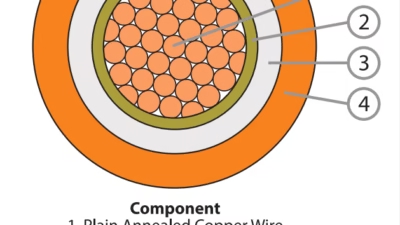
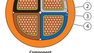
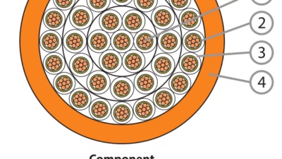
Understanding the precise layer structure of HD620 cables is essential for proper installation, termination, and maintenance. Each layer serves specific electrical, mechanical, or environmental protection functions.
| Layer | Material | Function | Thickness Range |
|---|---|---|---|
| Conductor | Stranded copper or aluminum (Class 2 per EN 60228) | Current transmission | Varies by cross-section (35-1000 mm²) |
| Conductor Screen | Semi-conducting extruded compound | Electric field uniformity at conductor surface | 0.5-1.0 mm |
| Insulation | Cross-linked polyethylene (XLPE) | Primary electrical insulation | 3.6 mm (6/10 kV) to 8.0 mm (18/30 kV) |
| Insulation Screen | Semi-conducting extruded compound | Electric field control at insulation surface | 0.8-1.2 mm |
| Metallic Screen | Copper wires or aluminum tape | Fault current return path, electromagnetic shielding | 16-35 mm² cross-section |
| Water Barrier | Longitudinally applied polymer tape | Moisture ingress prevention | 0.2-0.4 mm |
| Outer Sheath | Polyolefin compound (Z1) or PE/PVC | Mechanical and environmental protection | 2.0-3.5 mm |
4.4 Specialized Variations
HD620 encompasses numerous specialized cable types to address specific application requirements. Part 10-A through 10-P specifications cover various sheath materials, screening arrangements, and construction methods tailored to different installation environments and operational demands.
Common HD620 Part 10 Variations
- HD620 10-A: XLPE insulation with PE or PVC sheath, conventional concentric copper screening
- HD620 10-B: XLPE insulation with polyolefin compound sheath, enhanced fire performance options
- HD620 10-E: Polyolefin compound sheath with superior fire performance (Types 10E-1 through 10E-8)
- HD620 10-F: Various configurations for aerial systems, including messenger-supported designs
- HD620 10-I: Triplex formation cables for overhead distribution systems
5. Standards Compliance and Specifications
5.1 International Standard Framework
HD620 cables must satisfy comprehensive testing requirements that exceed basic IEC 60502-2 specifications. The compliance methodology references HD 605 for material testing protocols, with Subclause 2.1.1 governing insulation material testing and Subclause 2.1.2 addressing sheath material evaluation unless otherwise specified in particular HD620 sections.
5.2 Voltage Classification System
The HD620 standard employs a precise voltage designation system denoting both the rated voltage to earth (U₀) and the rated voltage between phases (U), expressed in kilovolts. This classification system ensures proper cable selection for specific network configurations.
| Voltage Designation (U₀/U kV) | Maximum System Voltage (Um kV) | Typical Applications | Insulation Thickness Range |
|---|---|---|---|
| 3.6/6 | 7.2 | Small distribution networks, industrial plants | 2.5-3.4 mm |
| 6/10 | 12 | Urban distribution systems, medium industries | 3.4-4.5 mm |
| 8.7/15 | 17.5 | Regional distribution networks | 4.5-5.5 mm |
| 12/20 | 24 | Primary distribution systems, large industrial facilities | 5.5-6.5 mm |
| 18/30 | 36 | Subtransmission systems, major industrial installations | 7.0-8.0 mm |
| 20.8/36 | 42 | High-capacity distribution networks | 8.0-9.0 mm |
5.3 Conductor Specifications
HD620 mandates conductor compliance with EN 60228 specifications, which defines conductor classes based on flexibility requirements. The standard accommodates both copper and aluminum conductors, with specific provisions for compact round (K) and sector-shaped (S) conductor configurations to optimize cable geometry and performance characteristics.
Standard Conductor Cross-Sections (mm²)
Available Sizes: 16, 25, 35, 50, 70, 95, 120, 150, 185, 240, 300, 400, 500, 630, 800, 1000
Current Carrying Capacity Example (12/20 kV XLPE Cable, Direct Burial, 25°C Ambient):
- 95 mm² Copper: 320-340 A
- 150 mm² Copper: 405-430 A
- 240 mm² Copper: 520-560 A
- 400 mm² Copper: 675-720 A
- 630 mm² Copper: 855-920 A
Note: Actual current ratings depend on installation method, ambient temperature, soil thermal resistivity, and grouping factors. Consult detailed cable datasheets for specific applications.
5.4 Testing Requirements
Comprehensive type testing and routine testing protocols ensure HD620 cable reliability and performance. Critical tests include:
| Test Category | Test Description | Acceptance Criteria | Reference Standard |
|---|---|---|---|
| Electrical | AC voltage withstand test | 2.5 × U₀ for 15 minutes (no breakdown) | EN 60885-3 |
| Electrical | Partial discharge measurement | ≤10 pC at 1.73 × U₀ | HD 605 |
| Electrical | Impulse voltage test | Withstand specified BIL without failure | EN 60060-1 |
| Mechanical | Bending test | No cracking or damage at specified radius | EN 60811-1-4 |
| Thermal | Heat cycle test | 20 cycles at 90°C conductor temperature | HD 605 |
| Environmental | Water penetration test | No water passage beyond 2 meters | HD 605 |
| Fire Performance | Flame propagation (single cable) | Self-extinguishing per EN 60332-1-2 | EN 60332-1-2 |
| Fire Performance | Flame propagation (bundled) | Limited spread per EN 60332-3-23/24 | EN 60332-3-23 |
6. Safety Thresholds and Ratings
6.1 Temperature Limitations
Strict temperature limitations ensure safe operation and prevent premature cable degradation. Exceeding these thresholds can result in accelerated aging, insulation breakdown, and potential system failures.
Critical Temperature Thresholds
| Operating Condition | Maximum Conductor Temperature | Duration |
|---|---|---|
| Normal Continuous Operation | 90°C | Continuous (design life: 40+ years with TR-XLPE) |
| Emergency Overload | 130°C | Maximum 100 hours per year (reduced service life) |
| Short Circuit | 250°C | Maximum 1-5 seconds |
| Installation (Minimum) | -5°C to 0°C | During cable handling and laying |
| Storage (Minimum) | -40°C | Long-term storage capability |
6.2 Minimum Bending Radius
Proper bending radius observance is critical to prevent mechanical damage to conductor strands, insulation screen integrity, and metallic screen continuity. Violations can create localized stress points leading to premature cable failure.
Bending Radius Requirements
Example: A 12/20 kV cable with 35 mm OD requires minimum bending radius of 525 mm (15 × 35 mm) during installation and 700 mm (20 × 35 mm) for fixed bends.
6.3 Short Circuit Current Ratings
Short circuit withstand capability depends on conductor cross-section, initial temperature, and fault duration. The adiabatic equation provides theoretical maximum short circuit current:
Where:
Isc = Short circuit current (A)
A = Conductor cross-sectional area (mm²)
k = Material constant (copper: 115, aluminum: 76)
t = Fault duration (seconds)
6.4 Voltage Drop Considerations
Maximum allowable voltage drop typically ranges from 3-5% under normal load conditions to maintain power quality and equipment performance. Voltage drop calculations must account for conductor resistance, reactance, load power factor, and cable length.
| Conductor Size (mm²) | AC Resistance at 90°C (Ω/km) | Reactance at 50 Hz (Ω/km) | Voltage Drop (V/A/km) |
|---|---|---|---|
| 50 Cu | 0.493 | 0.120 | 0.505 |
| 95 Cu | 0.258 | 0.110 | 0.282 |
| 150 Cu | 0.164 | 0.105 | 0.195 |
| 240 Cu | 0.103 | 0.095 | 0.139 |
| 400 Cu | 0.062 | 0.088 | 0.106 |
7. Installation Precautions and Best Practices
7.1 Pre-Installation Planning
Thorough pre-installation planning prevents costly errors and ensures optimal cable performance throughout its operational life. Critical planning considerations include route surveying, thermal environment assessment, electromagnetic interference evaluation, and accessibility for future maintenance operations.
Pre-Installation Checklist
- Verify cable specifications match system voltage, current requirements, and environmental conditions
- Confirm adequate cable pulling tension margins (typically maximum 50 N/mm² for copper, 30 N/mm² for aluminum)
- Assess soil thermal resistivity for direct burial installations (optimal: ≤1.0 K·m/W)
- Calculate derating factors for grouped cables, elevated ambient temperatures, and soil conditions
- Identify and plan for crossing points with existing utilities to prevent mechanical damage
- Prepare cable storage area with proper support to prevent mechanical stress
7.2 Handling and Transportation
Proper cable handling during transportation and site movement prevents insulation damage and conductor deformation that may not be immediately visible but can compromise long-term reliability.
- Never drop cable drums from height; use controlled lowering equipment rated for drum weight
- Maintain minimum bending radius during unreeling operations (15-20 × OD depending on cable type)
- Protect cable ends from moisture ingress using appropriate sealing caps or heat-shrink closures
- Store drums on firm, level ground with proper chocking to prevent uncontrolled rolling
- Avoid dragging cables across sharp edges, rocks, or abrasive surfaces that can damage outer sheaths
- Inspect cable for visible damage before installation; reject sections showing sheath cuts, deformation, or crushing
7.3 Installation Method-Specific Guidelines
Direct Burial Installation
Direct burial represents the most economical installation method for many HD620 applications, particularly in rural and suburban distribution networks. Proper installation technique significantly impacts cable service life and reliability.
| Parameter | Recommendation | Rationale |
|---|---|---|
| Minimum Burial Depth | 800-1000 mm | Protection from mechanical damage, frost heave, temperature variation |
| Trench Bottom Preparation | 100 mm sand bedding | Uniform support, prevention of point loading |
| Cable Protection | 100 mm sand cover + warning tape | Cushioning, future excavation warning |
| Backfill Material | Screened soil, stone-free | Prevention of sheath damage during settling |
| Horizontal Spacing (Parallel Cables) | ≥300 mm (thermal derating consideration) | Adequate heat dissipation between circuits |
| Cable Marking Posts | Every 50-100 m + direction changes | Route identification for future reference |
Duct and Conduit Installation
Duct installations offer enhanced protection and facilitate future cable replacement but require careful attention to pulling tensions, sidewall pressure, and heat dissipation characteristics.
- Calculate maximum pulling tension using manufacturers’ data, considering duct friction coefficients (typically 0.30-0.50)
- Use appropriate pulling lubricants compatible with cable sheath materials to reduce friction
- Install pull-through wire or rope immediately after duct placement to facilitate future cable installation
- Maintain duct fill ratio below 40% for single cables, 35% for multiple cables to ensure adequate ventilation
- Seal duct ends with fire-rated compound to prevent fire propagation between duct sections
7.4 Termination and Jointing Best Practices
High-quality terminations and joints are essential for maintaining cable system integrity. Poor workmanship at these critical interfaces accounts for a significant percentage of medium voltage cable failures.
Termination Quality Control Points
- Cleanliness: Work in clean, dry environment; use isopropyl alcohol or manufacturers’ approved cleaners for surface preparation
- Screen Continuity: Ensure proper connection of metallic screen to earthing system with low-resistance bond (typically <0.1 Ω)
- Stress Control: Apply stress control components precisely per manufacturers’ instructions to prevent electric field concentration
- Insulation Shielding: Remove semi-conducting screens to exact lengths specified; irregular removal creates high-stress points
- Moisture Exclusion: Complete all work expeditiously; use heat-shrink or cold-shrink moisture barriers immediately after preparation
- Quality Verification: Perform insulation resistance testing (minimum 100 MΩ at 500V DC) before energization
7.5 Environmental Considerations
Environmental factors profoundly influence cable performance and longevity. Special provisions may be necessary for challenging installation environments.
| Environmental Challenge | Impact | Mitigation Strategy |
|---|---|---|
| High Soil Thermal Resistivity (>2.5 K·m/W) | Reduced current capacity, thermal aging acceleration | Thermal backfill, increased conductor size, forced ventilation |
| Corrosive Soil (pH <5.5 or >8.5) | Metallic component degradation, sheath damage | Enhanced sheath protection, cathodic protection systems |
| High Water Table | Water treeing risk, buoyancy forces | TR-XLPE insulation, concrete weights, watertight joints |
| Termite-Prone Regions | Sheath penetration by insects | Metal-sheathed cables, chemical treatment of backfill |
| Seismic Activity Zones | Ground movement-induced stress | Flexible joints, expansion loops, segmented routes |
8. Common Problems and Troubleshooting
8.1 Water Treeing
Water treeing represents one of the most insidious degradation mechanisms affecting XLPE-insulated medium voltage cables. This phenomenon occurs when moisture penetrates the insulation under electrical stress, forming tree-like patterns of microscopic voids that progressively degrade dielectric strength.
Water trees develop through electrochemical processes when three conditions coincide: moisture presence within insulation, electrical stress from the operating voltage, and trigger points such as impurities, voids, or interface defects. Research documented by materials science studies indicates that water tree growth can reduce service life by 50% or more in conventional XLPE cables.
Prevention Strategies:
- Specify tree-retardant XLPE (TR-XLPE) insulation for high-moisture environments (service life: 40+ years vs 20-25 years for standard XLPE)
- Ensure comprehensive watertightness through longitudinal and radial water barriers
- Maintain excellent jointing and termination quality to prevent moisture ingress points
- Implement periodic partial discharge monitoring to detect early degradation
- Consider metallic moisture barriers (lead sheaths) for submarine or permanently submerged applications
8.2 Electrical Treeing
Electrical trees occur when localized electric field intensification exceeds insulation breakdown strength, creating conductive carbonized paths through the dielectric. Unlike water trees, electrical trees develop rapidly once initiated and typically lead to complete insulation failure within hours to weeks.
Root Causes and Prevention
| Root Cause | Manifestation | Prevention Method |
|---|---|---|
| Incomplete screen removal | Field concentration at screen stubs | Precise screen stripping per manufacturer specifications |
| Contaminated insulation surface | Surface tracking, flashover | Clean work environment, approved cleaning agents |
| Inadequate stress control | High electric fields at terminations/joints | Properly sized stress control components, correct installation |
| Void formation during installation | Partial discharge inception | Proper mastic application, void-free accessories |
| Conductor screen protrusions | Local field enhancement | Smooth screen termination, avoid cutting into insulation |
8.3 Mechanical Damage
Mechanical damage during installation or service represents a leading cause of premature cable failure. Damage may be immediately evident or develop insidiously, manifesting years after the causative incident.
Common Mechanical Failure Modes
- Excessive Bending: Violation of minimum bending radius causes conductor strand breakage, screen wire fracture, and insulation stress concentration. Symptoms include increased resistance, intermittent faults, and eventual complete failure at bend locations.
- Pulling Tension Overload: Excessive pulling force during installation elongates conductors, breaks screen wires, and can separate insulation layers. Maximum safe pulling tension: 50 N/mm² for copper, 30 N/mm² for aluminum conductors.
- Impact Damage: Dropping cable drums or striking cables with excavation equipment causes localized crushing that may not penetrate the outer sheath but creates internal voids and stress risers leading to delayed breakdown.
- Sidewall Pressure: Excessive sidewall bearing pressure in duct bends (>500 N/m) can deform cable cross-section, damage screens, and create voids at the insulation-screen interface.
8.4 Thermal Overloading
Operating cables above design temperature accelerates insulation aging exponentially. The Arrhenius equation predicts that each 10°C temperature increase above rated conditions halves remaining insulation life.
Thermal Overload Indicators
- Increased partial discharge activity detected through online monitoring
- Elevated earth screen current indicating unbalanced loading or circulating currents
- Visible discoloration or deformation of accessible cable sections
- Distinctive odor from cable terminations suggesting thermal degradation
- Progressive increase in dissipation factor (tan δ) measurements
Corrective Actions:
- Install temperature monitoring at critical circuit locations (typically 85°C alarm, 90°C trip)
- Perform thermal imaging surveys to identify hot spots indicating improper installation or degradation
- Verify actual load profiles match design assumptions; implement load management if necessary
- Assess soil thermal resistivity periodically; consider thermal backfill if values exceed design assumptions
- Calculate actual derating factors for installations; compare against nameplate ratings
8.5 Diagnostic and Testing Approaches
Modern diagnostic techniques enable condition-based maintenance strategies that optimize cable system reliability while controlling costs.
| Diagnostic Method | Parameters Measured | Application | Typical Cost |
|---|---|---|---|
| Partial Discharge (Online) | PD magnitude, location, frequency | Continuous monitoring, early fault detection | High (permanent installation) |
| Partial Discharge (Offline) | PD at elevated test voltage | Commissioning testing, periodic assessment | Moderate |
| Tan Delta (Dissipation Factor) | Insulation quality indicator | Aging assessment, moisture detection | Moderate |
| Time Domain Reflectometry | Impedance discontinuities, fault location | Fault location, cable characterization | Low |
| VLF Withstand Testing | Insulation integrity verification | After installation, periodic proof testing | Moderate |
| Thermal Imaging | Surface temperature distribution | Hot spot identification, joint quality assessment | Low |
8.6 Failure Analysis and Root Cause Investigation
Systematic failure analysis provides invaluable feedback for preventing recurrence and optimizing maintenance strategies. When cable failures occur, preserve failed sections for detailed laboratory examination including:
- Visual and microscopic examination of failure location and propagation path
- Insulation screening electron microscopy to identify water tree or electrical tree signatures
- Chemical analysis of degradation products indicating thermal or electrical stress
- Mechanical testing of conductor and screen integrity at failure zone
- Correlation of failure characteristics with installation records and operational history
9. Contact Information
For detailed technical specifications, custom cable solutions, or product inquiries regarding HD620 standard cables, please contact Anhui Feichun Special Cable Co., Ltd.
Anhui Feichun Special Cable Co., Ltd. (安徽飞纯特种电缆有限公司) specializes in manufacturing high-quality medium voltage cables compliant with international standards including HD620, IEC 60502, and various national specifications.