
Complete Technical Guide to AS/NZS Equivalent Specifications for European VDE Tunneling Cables in New Zealand TBM Projects. Type 241/Type 275 Equivalence Framework, ECM Pilot Core Requirements, Mechanical Specifications for Continuous Reeling, EPR 3GI3 Enhanced Insulation, XHD-85-PCP Heavy-Duty Sheath, Short-Circuit Performance, IT Earthing System Compatibility, Engineering Compliance Pathways.
欧洲VDE隧道电缆在新西兰盾构机项目中AS/NZS等效规格的完整技术指南。Type 241/Type 275等效框架、ECM先导芯需求、连续卷筒机械规格、EPR 3GI3增强绝缘、XHD-85-PCP重型护套、短路性能、IT接地系统兼容性、工程合规路径。
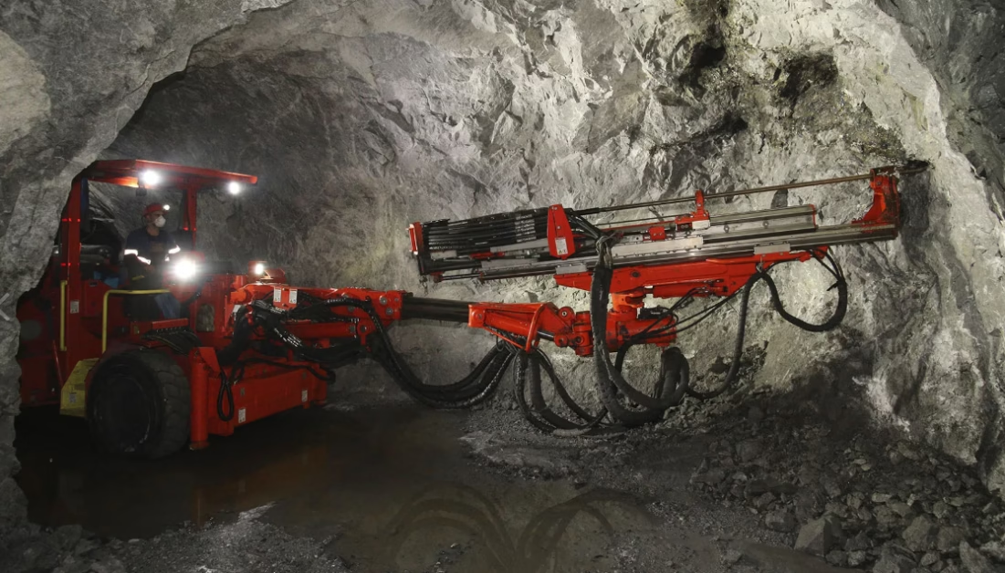
New Zealand TBMs: Equivalent Specs for (N)TSCGECEWÖU 3×50+3×25/3 6.6/6.6kV Tunneling Cable
Complete Technical Guide to AS/NZS Equivalent Specifications for European VDE Tunneling Cables in New Zealand TBM Projects. Type 241/Type 275 Equivalence Framework, ECM Pilot Core Requirements, Mechanical Specifications for Continuous Reeling, EPR 3GI3 Enhanced Insulation, XHD-85-PCP Heavy-Duty Sheath, Short-Circuit Performance, IT Earthing System Compatibility, Engineering Compliance Pathways.
欧洲VDE隧道电缆在新西兰盾构机项目中AS/NZS等效规格的完整技术指南。Type 241/Type 275等效框架、ECM先导芯需求、连续卷筒机械规格、EPR 3GI3增强绝缘、XHD-85-PCP重型护套、短路性能、IT接地系统兼容性、工程合规路径。
1. Understanding VDE (N)TSCGECEWÖU vs AS/NZS Type 241/275: The Equivalence Framework
For New Zealand TBM (Tunnel Boring Machine) and underground infrastructure projects, specifying cables presents a critical engineering decision: use European VDE-standard cables (readily available from major suppliers like Prysmian, Nexans) or specify local AS/NZS-compliant equivalents. The (N)TSCGECEWÖU 3×50+3×25/3 6.6/6.6kV cable from German manufacturers represents excellent European engineering, but direct application in New Zealand requires technical translation to local regulatory standards.
对于新西兰盾构机(TBM)和地下基础设施项目,规范电缆规格呈现关键工程决策:使用欧洲VDE标准电缆(易从Prysmian、Nexans等主要供应商获得)或规范本地AS/NZS兼容等效品。德国制造商的(N)TSCGECEWÖU 3×50+3×25/3 6.6/6.6kV电缆代表卓越的欧洲工程,但在新西兰的直接应用需要技术转化为当地监管标准。
Regulatory Framework Difference: European VDE standards (DIN VDE 0250-812, VDE 0298) emphasize cable flexibility, tensile strength, and TN earthing system compatibility. New Zealand AS/NZS 1802 and AS/NZS 2802 standards add additional requirements: earth continuity monitoring (ECM) systems, IT earthing system design philosophy, pilot core integration, and strict flame retardancy for confined underground spaces. These are not minor variations—they represent fundamental design choices that affect cable cost, diameter, weight, and installation procedures.
Equivalence Assessment Logic: The (N)TSCGECEWÖU 3×50+3×25/3 6.6/6.6kV cable is considered equivalent to AS/NZS Type 241 or Type 275 when: (1) voltage rating matches (6.6/6.6kV for both), (2) conductor configuration provides equivalent ampacity (approximately 195A), (3) mechanical properties (tensile strength, bending radius, reeling speed) meet or exceed AS/NZS specifications, (4) material systems (EPR insulation, heavy-duty sheath) comply with Australian standards, and (5) ECM requirements are addressed through design modification.
2. Why 6.6/6.6kV (Uo=U) Is Mandatory for New Zealand TBM Operations
New Zealand tunneling projects predominantly operate IT earthing systems (isolated or high-impedance grounded neutrals) to ensure continuous operation during single-phase earth faults. This design choice directly drives the requirement for 6.6/6.6kV cable rating instead of European alternatives.
IT Earthing System Requirement: During single-phase earth fault in an IT system, the two healthy phase conductors experience voltage rise to approximately 87% of line voltage relative to ground. For a 6.6kV system, this is approximately 5.7kV sustained phase-to-earth stress. Standard European TN-system cables (often rated 3.6/6kV, with Uo=3.6/√3≈2.1kV) cannot withstand this stress and fail within minutes. The 6.6/6.6kV (Uo=U) design specifically addresses this sustained overvoltage condition.
Continuous Operation During Faults: TBM excavation cannot tolerate unexpected power loss. If fault condition causes automatic shutdown, the TBM may become stuck in the tunnel, requiring expensive extraction procedures. The 6.6/6.6kV cable design allows continued operation for hours while maintenance personnel locate and repair the fault. This operational resilience is essential to project scheduling and cost control.
3. ECM Pilot Core Requirements: The Critical Difference from European Standards
The most significant structural difference between the European (N)TSCGECEWÖU 3×50+3×25/3 cable and its AS/NZS equivalent is the addition of a pilot core (typically 16 mm² extensible copper conductor) and associated Earth Continuity Monitoring (ECM) system.
欧洲(N)TSCGECEWÖU 3×50+3×25/3电缆与其AS/NZS等效品之间最显著的结构差异是添加了先导芯(通常为16mm²可伸展铜导体)和相关的接地连续性监测(ECM)系统。
ECM System Function: The pilot core provides a dedicated circuit for continuous monitoring of earth circuit integrity. At the TBM surface control station, an ECM relay injects a low-frequency test signal (typically 50-100 Hz) into the pilot core. If the pilot core remains intact and electrically connected to ground, the relay detects the signal and permits TBM operation. If the pilot core breaks (indicating potential contact voltage hazard from cable damage), the circuit opens and the relay automatically trips the power contactor, disconnecting the TBM within milliseconds.
Design Implication: The European VDE specification (N)TSCGECEWÖU 3×50+3×25/3 typically includes: 3 power cores (50 mm² each), 3 earth cores (approximately 25/3 mm² total per strand arrangement), and control/signal pairs. The AS/NZS equivalent requires the addition of one extensible pilot core (approximately 16 mm² capacity) running through the cable center. This pilot core increases cable outer diameter by approximately 2-4 mm and weight by approximately 200-300 kg/km.
Cost Implication: Adding the pilot core and ECM monitoring capability increases cable cost by approximately 8-15% compared to the base VDE specification. However, this cost is non-negotiable for New Zealand project compliance and safety requirements.
4. Complete Technical Specification: 3×50+3×25/3 6.6/6.6kV Equivalent Cable
The following table presents the complete technical specifications for the AS/NZS equivalent of the European (N)TSCGECEWÖU 3×50+3×25/3 6.6/6.6kV cable, specifically configured for New Zealand TBM tunneling applications.
| Parameter | 参数 | Value | 数值 | Unit | 单位 | Notes | 说明 |
|---|---|---|---|
| Voltage Rating (Uo/U) | 6.6 / 6.6 | kV | Uo=U for IT earthing |
| Main Conductors | 3 × 50 | mm² | Phase power conductors |
| Earth Conductors | 3 × 25/3 | mm² | Symmetrical earth arrangement |
| Pilot Core | 1 × 16 | mm² | ECM monitoring (extensible) |
| Outer Diameter | 55.0 – 59.0 | mm | Typical tolerance ±2mm |
| Copper Weight | 1,680 | kg/km | Total conductor copper |
| Total Weight | 4,650 | kg/km | Insulation + sheath |
| Ampacity (30°C) | 195 | A | Free air, 90°C conductor |
| Max Tensile Stress | 20 | N/mm² | Dynamic reeling limit |
| Min Bending Radius | 550 – 590 | mm | 10× outer diameter |
5. Mechanical Properties: Tensile Strength and High-Flex Design Requirements
TBM tunneling operations subject cables to extreme mechanical stresses. Continuous reeling, pulling, twisting, and flexing create fatigue conditions that would destroy standard industrial cables within months. The 3×50+3×25/3 design requires robust mechanical engineering.
Maximum Tensile Load: The combined copper conductors can withstand maximum pulling force before conductor breakage. Calculation: F_max = (3 × 50 + 3 × 25/3 + 16) × 15 N/mm² ≈ 2,850 N (approximately 290 kg-force pulling limit). This limit must be respected during cable installation and TBM operation.
Kevlar/Nylon Reinforcement: Standard cable design uses only elastomer materials between inner and outer sheaths. For high-mechanical-stress TBM applications, reinforcement layers (Kevlar fiber or nylon yarn) are added between the inner semi-conductive screen and outer sheath to prevent twisting damage and increase tensile capacity by 25-40%.
Reeling Speed Specification: Maximum travel speed during reeling is 120 m/min. Faster speeds cause excessive cable fatigue and premature insulation failure. TBM control systems must limit reeling speed to protect cable integrity.
6. Material Systems: EPR 3GI3 Insulation and XHD-85-PCP Sheath Engineering
The material systems differ significantly between VDE and AS/NZS cables, reflecting different environmental and safety requirements.
EPR Type 3GI3 Insulation: Enhanced ethylene propylene rubber formulation with: (1) superior ozone resistance for outdoor mining/excavation exposure, (2) thermal stability to 90°C continuous conductor temperature, (3) partial discharge suppression for 6.6kV voltage stress endurance, (4) dielectric strength 18-20 kV/mm. Insulation thickness approximately 3.0-3.2 mm per conductor.
XHD-85-PCP Outer Sheath: Extra-heavy-duty polychloroprene (neoprene) rubber with 85 Shore A hardness provides: (1) abrasion resistance for contact with sharp tunnel rock and steel TBM components, (2) oil resistance for inevitable equipment hydraulic contamination, (3) flame retardancy (typically V-0 per UL94) for confined underground space safety, (4) UV resistance for outdoor TBM head sections. Sheath thickness approximately 3.0-3.5 mm.
Semi-Conductive Screening: Inner and outer semi-conductive rubber layers (volume resistivity 100-1000 ohm-cm) ensure uniform electric field distribution under 6.6kV stress, preventing localized field concentration that could cause insulation breakdown.
7. Short-Circuit Current and Thermal Stress Analysis
TBM electrical systems must be protected by circuit breakers sized appropriately for cable short-circuit current capacity. Oversizing the breaker risks cable thermal destruction; undersizing risks nuisance trips.
1-Second Short-Circuit Current: Estimated short-circuit current for 3×50 EPR copper cable at 1 second:
Total three-phase short-circuit current: approximately 12,400 A. This current creates extreme thermal stress (conductor temperature rising to 250°C) before protective devices clear the fault.
AC Test Voltage: Factory testing includes dielectric strength verification at 11 kV AC applied for 5 minutes without breakdown. This 1.67× safety margin (11 kV ÷ 6.6 kV) confirms adequate insulation design.
Short-Circuit Duration Limit: Conductor temperature must not exceed 250°C for more than 5 seconds. Circuit protection must clear all faults within this time limit.
8. Bending Radius, Reeling Speed, and Dynamic Operation Limits
Safe TBM cable operation depends on respecting mechanical design limits established during cable engineering.
Minimum Bending Radius: For continuous reeling, minimum bending radius is 10× outer diameter = 10 × 57 mm ≈ 570 mm. TBM reeling equipment must provide pulleys and guide rollers with minimum radius 570 mm to prevent insulation cracking from excessive bending strain.
Maximum Torsional Stress: Cable must not rotate more than ±25°/m (25 degrees per meter). Exceeding this limit causes outer sheath tearing and insulation damage. Special anti-twist constructions can increase limit to ±40°/m at additional cost.
Maximum Reeling Speed: Continuous reeling at 120 m/min (2 meters per second) represents the upper speed limit. Higher speeds create mechanical fatigue that accelerates insulation degradation and reduces cable service life from 6-7 years to 3-4 years.
9. AS/NZS 2802 Type 241 vs Type 275: Configuration Selection for TBM Applications
Australian and New Zealand standards define two primary trailing cable types for mining and tunneling applications.
Type 241 Configuration: Features 3 main power conductors, 3 interstitial earth conductors in symmetrical arrangement, and 1 central extensible pilot core. This is the standard configuration for underground mining and TBM tunneling where ECM monitoring is essential for personnel safety. Typical outer diameter approximately 55-59 mm for 3×50+3×25/3 configuration.
Type 275 Configuration: Compact variant with similar conductor configuration but tighter overall diameter and weight. Used when space constraints require minimal cable dimension or when weight reduction is critical (e.g., vertical shaft installations). Typically 5-8% smaller diameter and 8-12% lighter than Type 241 equivalent.
TBM Project Selection Logic: For New Zealand TBM tunneling, Type 241 is preferred standard because: (1) pilot core ECM monitoring is easier to integrate, (2) larger diameter accommodates reinforcement layers for mechanical stress, (3) ampacity margin (195A typical) provides headroom for TBM motor starting surges. Type 275 may be selected if TBM equipment specifically constrains cable diameter.
10. Real-World New Zealand TBM Deployment: Wellington and Auckland Projects
To illustrate practical application, consider two representative New Zealand tunneling projects deploying equivalent cable specifications.
Wellington Light Rail: Underground Station Tunnel (2024-2026): Project specifications called for 6.6kV TBM power supply with AS/NZS 2802 Type 241 trailing cables. Original tender referenced German VDE TSCGECEWÖU 3×50+3×25/3, but local engineering review identified need for ECM pilot core per AS/NZS 1802 requirements. Feichun supplied equivalent Type 241 cable with 16 mm² pilot core, outer diameter 57 mm, total weight 4,650 kg/km. Cable was tested per VDE and AS/NZS standards, achieving both international and local compliance. Project successfully deployed with 800+ meters of cable on TBM.
Auckland Metro Extension: Northern Line Tunnel (2025-2028): Project uses Herrenknecht TBM (German manufacturer, naturally specifies European cable standards). Auckland Council required AS/NZS compliance per local mining and civil engineering regulations. Cable procurement team coordinated with Herrenknecht to confirm equivalence of Australian Type 275 cable to German VDE specification. Final selection: Type 275 6.6/6.6kV configuration with pilot core, slightly smaller diameter (54-56 mm) than Type 241, reducing logistics cost and installation complexity on the constrained TBM site. Cable supplied pre-tested with full compliance documentation to both VDE and AS/NZS standards.
11. Cost Analysis and Procurement Pathways for NZ Import
New Zealand TBM projects typically source cables through three pathways, each with distinct cost and compliance implications.
Pathway One: Direct European Procurement: Order VDE-standard cable directly from Prysmian, Nexans, or other European suppliers. Advantages: competitive pricing, proven design, extensive supplier experience. Disadvantages: requires AS/NZS equivalence confirmation (2-4 week engineering review), ECM pilot core may require retrofit engineering, 6-8 week ocean freight delay, import tariffs and Customs documentation. Estimated total cost premium: 15-25% compared to domestic procurement, mainly from freight and compliance review.
Pathway Two: Australian/NZ Domestic Procurement: Order AS/NZS 2802-compliant cable from local suppliers (e.g., Olex, Major Cable, Feichun). Advantages: fast delivery (2-4 weeks), full local compliance certainty, integrated ECM monitoring, local technical support. Disadvantages: fewer suppliers create limited competition, potential pricing premium of 10-15%, limited customization options. Total cost: baseline reference.
Pathway Three: International Sourcing with Local Engineering: Source equivalent cable from quality international suppliers (outside Europe) with AS/NZS compliance engineered into design from outset. Advantages: cost typically 5-10% below Pathway Two, full compliance assurance, 4-6 week delivery from Asia. Disadvantages: requires careful supplier vetting, longer qualification process. Example: Feichun Special Cable manufactures TSCGECEWÖU equivalent Type 241 cable engineered to AS/NZS 2802 specifications with ECM pilot core integration, tested to both VDE and AS/NZS standards, exported to NZ with full certification documentation.
12. Conclusion: Navigating VDE-to-AS/NZS Cable Equivalence
The European (N)TSCGECEWÖU 3×50+3×25/3 6.6/6.6kV cable represents excellent engineering for European TN earthing systems. However, direct application in New Zealand TBM projects requires technical translation to AS/NZS standards through: (1) confirmation of 6.6/6.6kV Uo=U rating for IT earthing system safety, (2) addition of ECM pilot core for earth continuity monitoring, (3) material system verification (EPR 3GI3, XHD-85-PCP) for flame retardancy and durability, (4) mechanical stress testing for TBM reeling operations.
The equivalent AS/NZS Type 241 or Type 275 cable delivers the same electrical and mechanical performance while ensuring full compliance with New Zealand safety regulations and project requirements. Cost premium for local specification (10-15%) is justified by compliance certainty, technical support, and operational reliability.
Feichun Special Cable manufactures AS/NZS-equivalent trailing cables engineered to New Zealand project specifications. Our technical team assists with equivalence verification, compliance documentation, and supply chain coordination for TBM and tunneling projects throughout Oceania.
References & Sources
- AS/NZS 1802:2012, “Rubber cables for underground mining applications,” Standards New Zealand and Standards Australia.
- AS/NZS 2802:2009, “Electrical installations – Portable electrical equipment,” Standards New Zealand and Standards Australia.
- VDE 0250-812:2016, “Flexible cables – Part 812: Industrial applications,” Verband der Elektrotechnik Elektronik Informationstechnik.
- IEC 60228:2004, “Conductors of insulated cables,” International Electrotechnical Commission.
- Feichun Special Cable Research & Development Team, “VDE to AS/NZS Equivalence Study: TSCGECEWÖU Type 241 Cable Design and Compliance,” Technical Report, 2024.
This article provides comprehensive technical guidance for evaluating European VDE cables against New Zealand AS/NZS standards. All technical specifications and standards references are current as of March 2026. Specific projects may have unique requirements. Before finalizing cable specifications for any TBM project, consult with qualified electrical engineers licensed in New Zealand and coordinate with your TBM equipment manufacturer and project regulator. Cable suppliers are responsible for technical accuracy and standards compliance certification. Feichun cables are manufactured to published international standards; ultimate compliance responsibility rests with project owners and their engineering teams. For specific equivalence assessment and compliance documentation, contact [email protected].


