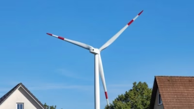
High-performance single-core cables with circular stranded compacted copper conductors, designed for demanding wind energy applications. Engineered for reliability in onshore and offshore wind farm installations with superior water-blocking capabilities.
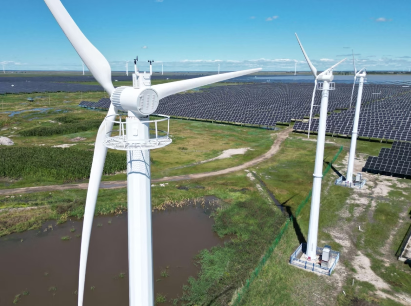
Wind Turbine Medium Voltage XLPE Power Cables
12/20 (24) kV — Longitudinally & Radially Sealed
High-performance single-core cables with circular stranded compacted copper conductors, designed for demanding wind energy applications. Engineered for reliability in onshore and offshore wind farm installations with superior water-blocking capabilities.
Technical Overview
Wind turbine medium voltage cables serve as the critical power transmission lifeline connecting wind turbine generators to step-up transformers and grid infrastructure. These cables must withstand extreme operational conditions including continuous mechanical stress from nacelle rotation, temperature fluctuations from -40°C to +90°C, and exposure to moisture in both onshore and offshore environments.
The 12/20 (24) kV XLPE-insulated cables manufactured by Anhui Feichun Special Cable Co., Ltd. feature longitudinal and radial water-blocking technology, ensuring reliable performance throughout the cable’s 30+ year design life. The cross-linked polyethylene (XLPE) insulation provides superior dielectric properties compared to traditional PVC, enabling higher operating temperatures and improved current-carrying capacity.
According to international standards, medium voltage cables with XLPE insulation offer excellent thermal stability with maximum conductor operating temperatures of 90°C for normal operation and 250°C short-circuit rating (5 seconds maximum duration). These parameters are essential for wind turbine applications where thermal management is critical.
“IEC 60502-2 specifies the construction, dimensions, and test requirements of power cables with extruded solid insulation for rated voltages from 6 kV up to 30 kV used in power distribution systems.”
The cable construction incorporates Class 2 circular stranded compacted copper conductors conforming to IEC 60228, providing optimal flexibility for wind turbine tower installations while maintaining excellent conductivity. The compacted design reduces overall cable diameter by approximately 10-12% compared to non-compacted conductors, offering significant weight savings in vertical tower runs.
Cable Construction & Materials
Copper Conductor (Class 2 RMC)
Circular stranded and compacted conductor per IEC 60228 Class 2, offering optimal balance between flexibility and current-carrying capacity. Available from 35 mm² to 1000 mm².
Conductor Screen
Extruded semi-conductive compound bonded to insulation, eliminating air voids and ensuring uniform electric field distribution at the conductor surface.
XLPE Insulation
5.5 mm cross-linked polyethylene insulation providing excellent thermal stability (90°C continuous), low dielectric losses, and superior moisture resistance.
Insulation Screen
Extruded semi-conductive layer with strippable interface for reliable field termination, meeting stringent partial discharge requirements.
Metallic Screen
Copper wire screen (16-50 mm²) provides fault current path and electromagnetic shielding. Screen sizing optimized for short-circuit capacity requirements.
Longitudinal & Radial Sealing
Water-swellable tapes and compounds prevent moisture migration along and through cable layers, critical for wind turbine reliability in harsh environments.
“HD 620 applies to cables with extruded insulation for rated voltages from 3.6/6 kV up to 20.8/36 kV used in power distribution systems. Test methods are specified in EN 60228, EN 60811, EN 60885-3, and HD 605.”
Physical & Dimensional Parameters
Cable Dimensions and Weight Specifications
12/20 (24) kV Single-Core XLPE Power Cables with Copper Conductor
| Conductor Size(mm²) | Conductor Ø(mm) | Insulation(mm) | Ø Over Insulation(mm) | Screen Size(mm²) | Ø Over Screen(mm) | Cable Ø (De)(mm) | Weight(kg/km) | Max Pull Force(kN) | Min Bend Radius(m) |
|---|---|---|---|---|---|---|---|---|---|
| 1×35RMC | 7.0 +0.15 | 5.5 | 19.2 | 16 | 23.1 | 27.9 | 990 | 1.75 | 0.42 |
| 1×50RMC | 8.25 +0.20 | 5.5 | 20.5 | 16 | 24.4 | 29.1 | 1140 | 2.5 | 0.44 |
| 1×70RMC | 9.6 +0.20 | 5.5 | 21.8 | 25 | 25.7 | 30.5 | 1450 | 3.5 | 0.46 |
| 1×95RMC | 11.5 +0.20 | 5.5 | 23.7 | 35 | 27.6 | 32.4 | 1830 | 4.75 | 0.49 |
| 1×120RMC | 12.9 +0.25 | 5.5 | 25.1 | 50 | 29.0 | 33.8 | 2230 | 6 | 0.51 |
| 1×150RMC | 14.5 +0.30 | 5.5 | 26.7 | 50 | 30.6 | 35.4 | 2520 | 7.5 | 0.53 |
| 1×185RMC | 16.0 +0.30 | 5.5 | 28.2 | 50 | 32.1 | 36.9 | 2890 | 9.25 | 0.55 |
| 1×240RMC | 18.5 +0.30 | 5.5 | 30.7 | 50 | 34.6 | 39.4 | 3460 | 12 | 0.59 |
| 1×300RMC | 20.5 +0.30 | 5.5 | 32.7 | 50 | 36.6 | 41.4 | 4060 | 15 | 0.62 |
| 1×400RMC | 23.5 +0.30 | 5.5 | 35.7 | 50 | 39.6 | 44.4 | 4940 | 20 | 0.67 |
| 1×500RMC | 26.5 +0.40 | 5.5 | 39.2 | 50 | 43.3 | 48.1 | 6050 | 25 | 0.72 |
| 1×630RMC | 30.3 +0.40 | 5.5 | 43.3 | 50 | 47.4 | 52.5 | 7460 | 31.5 | 0.79 |
| 1×800RMC | 34.6 +0.50 | 5.5 | 48.0 | 50 | 52.1 | 57.4 | 9170 | 40 | 0.86 |
| 1×1000RMC | 38.2 +0.40 | 5.5 | 51.6 | 50 | 55.7 | 61.4 | 11130 | 50 | 0.92 |
Note: RMC (RMC) designates Circular Stranded Compacted Conductor, Class 2 per IEC 60228. All dimensional tolerances comply with HD 620 S3:2023 requirements. The minimum bending radius values are for installation purposes; during operation, larger radii may be specified based on cable loading conditions.
Electrical Characteristics
Conductor & Screen Resistance Data
DC and AC resistance values at operating temperatures
| Size(mm²) | Conductor RDC @ 20°C(Ω/km) | Conductor RAC @ 90°C(Ω/km) | Screen RDC @ 20°C(Ω/km) | Screen RAC @ 80°C(Ω/km) | Field Stress Cond/Insul(kV/mm) | Capacitance C(µF/km) | Charging Current IC(A/km) | Inductance L(mH/km) |
|---|---|---|---|---|---|---|---|---|
| 1×35RMC/16 | 0.524 | 0.668 | 1.12 | 1.38 | 3.43/1.43 | 0.15 | 0.55 | 0.47–0.77 |
| 1×50RMC/16 | 0.387 | 0.494 | 1.12 | 1.38 | 3.27/1.48 | 0.16 | 0.61 | 0.45–0.74 |
| 1×70RMC/25 | 0.268 | 0.342 | 0.72 | 0.89 | 3.14/1.53 | 0.18 | 0.67 | 0.43–0.71 |
| 1×95RMC/35 | 0.193 | 0.247 | 0.51 | 0.63 | 3.0/1.58 | 0.20 | 0.75 | 0.40–0.67 |
| 1×120RMC/50 | 0.153 | 0.196 | 0.36 | 0.44 | 2.92/1.62 | 0.22 | 0.82 | 0.39–0.65 |
| 1×150RMC/50 | 0.124 | 0.159 | 0.36 | 0.44 | 2.85/1.65 | 0.23 | 0.89 | 0.37–0.63 |
| 1×185RMC/50 | 0.0991 | 0.128 | 0.36 | 0.44 | 2.79/1.68 | 0.25 | 0.95 | 0.36–0.62 |
| 1×240RMC/50 | 0.0754 | 0.0977 | 0.36 | 0.44 | 2.71/1.72 | 0.28 | 1.06 | 0.35–0.59 |
| 1×300RMC/50 | 0.0601 | 0.0787 | 0.36 | 0.44 | 2.66/1.75 | 0.30 | 1.15 | 0.34–0.58 |
| 1×400RMC/50 | 0.0470 | 0.0627 | 0.36 | 0.44 | 2.6/1.79 | 0.34 | 1.28 | 0.32–0.55 |
| 1×500RMC/50 | 0.0366 | 0.0503 | 0.36 | 0.44 | 2.53/1.8 | 0.38 | 1.42 | 0.31–0.54 |
| 1×630RMC/50 | 0.0283 | 0.0408 | 0.36 | 0.44 | 2.48/1.83 | 0.42 | 1.59 | 0.30–0.52 |
| 1×800RMC/50 | 0.0221 | 0.0340 | 0.36 | 0.44 | 2.44/1.86 | 0.48 | 1.79 | 0.30–0.50 |
| 1×1000RMC/50 | 0.0176 | 0.0292 | 0.36 | 0.44 | 2.41/1.88 | 0.52 | 1.95 | 0.29–0.48 |
“Compliance with IEC 60502-2 is critical for manufacturers offering medium voltage cables for renewable energy applications. Cables must undergo rigorous testing including insulation resistance measurements exceeding 1000 MΩ/km.”
Current-Carrying Capacity & Short Circuit Data
Ampacity Ratings by Installation Method
Current ratings for ground and air installations with various bonding configurations
| Size(mm²) | Conductor ISC(kA/s) | Screen ISC(kA/s) | Ground Installation (A) | Air Installation (A) | ||||||
|---|---|---|---|---|---|---|---|---|---|---|
| Flat BE | Flat SPB/CB | Trefoil BE | Trefoil SPB/CB | Flat BE | Flat SPB/CB | Trefoil BE | Trefoil SPB/CB | |||
| 1×35RMC/16 | 5.0 | 3.7 | 242 | 245 | 231 | 231 | 250 | 252 | 216 | 217 |
| 1×50RMC/16 | 7.2 | 3.7 | 287 | 292 | 274 | 275 | 300 | 303 | 259 | 260 |
| 1×70RMC/25 | 10.0 | 5.3 | 347 | 357 | 334 | 336 | 367 | 376 | 319 | 321 |
| 1×95RMC/35 | 13.6 | 7.1 | 411 | 431 | 402 | 406 | 442 | 461 | 389 | 392 |
| 1×120RMC/50 | 17.2 | 9.8 | 453 | 492 | 455 | 462 | 497 | 531 | 445 | 451 |
| 1×150RMC/50 | 21.5 | 9.8 | 501 | 555 | 511 | 521 | 558 | 606 | 505 | 514 |
| 1×185RMC/50 | 26.5 | 9.8 | 554 | 629 | 575 | 589 | 627 | 694 | 574 | 587 |
| 1×240RMC/50 | 34.3 | 9.8 | 624 | 735 | 666 | 687 | 722 | 824 | 675 | 695 |
| 1×300RMC/50 | 42.9 | 9.8 | 682 | 832 | 747 | 776 | 805 | 946 | 767 | 794 |
| 1×400RMC/50 | 57.2 | 9.8 | 750 | 955 | 846 | 887 | 906 | 1105 | 883 | 922 |
| 1×500RMC/50 | 71.5 | 9.8 | 818 | 1089 | 949 | 1006 | 1008 | 1281 | 1008 | 1064 |
| 1×630RMC/50 | 90.1 | 9.8 | 889 | 1244 | 1060 | 1138 | 1117 | 1491 | 1150 | 1227 |
| 1×800RMC/50 | 114.4 | 9.8 | 954 | 1403 | 1167 | 1271 | 1220 | 1716 | 1291 | 1395 |
| 1×1000RMC/50 | 143.0 | 9.8 | 1006 | 1554 | 1257 | 1387 | 1305 | 1931 | 1415 | 1548 |
Bonding Configurations: SPB = Single Point Bonded; CB = Cross Bonded; BE = Both Ends Bonded. Installation configurations reference: (1) Cables in trefoil formation with spacing equal to De; (2) Cables in flat formation (ground) with spacing De + 70 mm; (3) Cables in flat formation (air) with spacing 2×De.
Primary Applications
These medium voltage XLPE power cables are specifically engineered for the demanding requirements of wind energy generation systems. The combination of robust mechanical properties, superior electrical characteristics, and comprehensive water-blocking protection makes them ideal for both onshore and offshore wind farm installations.
🌊 Offshore Wind Farms
Inter-array cables connecting wind turbines to offshore substations. Longitudinal water blocking prevents moisture propagation in submarine and J-tube installations.
🏔️ Onshore Wind Parks
Tower cables and underground collection systems. Direct burial installation with radial sealing protects against groundwater infiltration.
⚡ Substation Connections
Medium voltage links between wind farm collection points and step-up transformer stations for grid integration.
“Wind turbines require cables that can withstand various environmental challenges including temperature variations, wind, and moisture. Power cables must be designed to ensure safe and efficient transmission of power from the nacelle through the tower to the grid.”
Industry-Leading Cable Solutions
For specialized applications in port machinery, crane systems, and industrial power distribution, we recommend exploring comprehensive cable solutions from our industry partner. Their expertise in heavy-duty reeling cables and marine applications complements our wind energy cable offerings.
Explore Crane & Port Machinery Cables →Standards Compliance & Certifications
HD 620 S3:2023
European harmonization document for distribution cables with extruded insulation, voltage ratings 3.6/6 kV to 20.8/36 kV. Part 10 Section R covers XLPE-insulated cables.
IEC 60502-2:2014
International standard specifying construction, dimensions and test requirements for power cables 6 kV to 30 kV with extruded solid insulation.
BS 7870-4.10:2011
British Standard for LV and MV polymeric insulated cables for use by distribution utilities, Part 4.10 covering single-core XLPE 12/20 kV cables.
DIN VDE 0276-620:2018
German national implementation of HD 620 for power cables with cross-linked insulation. N2XS(FL)2Y designation per VDE nomenclature.
IEC 60228
Conductor specification standard defining Class 2 stranded conductors used in medium voltage cables. Ensures consistent conductivity and flexibility.
IEC 60332-1-2
Flame propagation test requirements for single insulated cables. Ensures limited fire spread under specified test conditions.
Contact Our Technical Team
Anhui Feichun Special Cable Co., Ltd. — Your Partner in Wind Energy Cable Solutions