
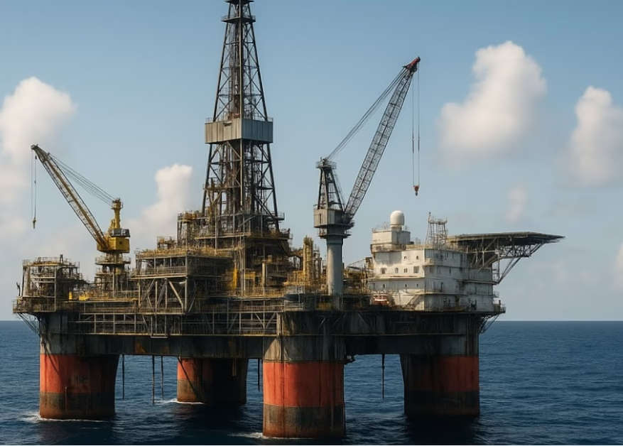
Troubleshooting NEK 606 UX/UX(I) Mud Resistant Grounding Cables on Offshore Platforms 在海上平台上排查NEK 606 UX/UX(I)耐泥浆接地电缆故障
Grounding cable systems represent one of the most critical—yet frequently overlooked—power distribution components on offshore drilling platforms and production facilities. NEK 606 UX and UX(I) grounding cables, developed and certified by the Norwegian Electrotechnical Committee for offshore applications, (由挪威电气标准委员会为海上应用开发的接地电缆) provide the essential fault current path and system voltage stabilization required to protect personnel and equipment during electrical transients, ground faults, and lightning events. However, when these cables are exposed to drilling mud, petrochemical fluids, and the harsh chemical environment of modern offshore operations, they become vulnerable to a distinct class of failure modes that demand specialized troubleshooting procedures.
This technical guide addresses the electrical and physical diagnostic procedures that electrical engineers and platform maintenance teams require to identify, assess, and remediate faults in NEK 606 grounding cable systems operating in offshore environments.
Understanding NEK 606 UX/UX(I) Cable Architecture and Failure Modes
NEK TS 606 is the Norwegian offshore technical specification covering halogen-free and mud-resistant cables for oil and gas, marine, and shipping industries, (NEK TS 606是挪威海上技术规范,涵盖无卤和耐泥浆电缆) established since 1993 with requirements exceeding the baseline international IEC 60092-360 marine cable standards. The UX designation specifically identifies grounding and bonding cables rated 0.6/1 kilovolt with the following structural characteristics:
Primary Conductor: Tinned annealed stranded copper wire per IEC 60228 Class 2 stranding specifications, (IEC 60228 Class 2绞合规范) with soft mechanical properties enabling installation flexibility in confined platform spaces. Conductor sizes range from 10 mm² (8 AWG) through 150 mm² (300 kcmil), with cross-sectional area directly determining ampacity and fault current carrying capacity.
Primary Insulation: Halogen-free thermosetting compound (SHF2 designation) or mud-resistant thermosetting compound (SHF MUD variant for UX(I) specification), (无卤热固化复合材料SHF2,或耐泥浆复合材料SHF MUD) engineered to resist petrochemical fluids, drilling mud immersion, saltwater exposure, and thermal cycling from -15°C to +90°C operating range. The UX(I) mud-resistant variant incorporates specially formulated outer sheath materials that maintain electrical and mechanical properties after prolonged exposure to synthetic drilling mud and invert emulsion systems, (UX(I)耐泥浆变体在长期钻井泥浆暴露后保持电气和机械性能).
Outer Sheath: Low-smoke zero-halogen (LSZH) thermosetting compound meeting IEC 60332-1 flame retardant and IEC 60332-3-22 Category A flame retardant standards, (满足IEC 60332-1和IEC 60332-3-22 Category A阻燃标准), with thickness typically 1.5-2.5 mm depending on conductor size and mud-resistance specification.
Critical Failure Mechanisms: Diagnostic Framework
NEK 606 UX/UX(I) cables operating in offshore environments fail through five primary mechanisms, each with distinct diagnostic signatures:
Mechanism 1: Mud Saturation and Sheath Degradation
When drilling mud containing hydrocarbon solvents, surfactants, and emulsifying agents contacts the cable sheath, three simultaneous processes occur: (1) the thermosetting material absorbs solvent molecules, causing controlled swelling; (2) polar solvents penetrate micro-cracks in the sheath, reaching the underlying insulation; (3) chemical incompatibility between mud formulation and sheath material causes crazing (微小裂纹) and stress-whitening visible on the cable surface.
The UX(I) mud-resistant designation provides significant protection but does not guarantee indefinite immunity. Standard UX cables exposed to continuous mud splash or immersion typically fail within 6-18 months, while UX(I) cables extend service life to 3-5 years under similar exposure conditions, (标准UX电缆在连续泥浆喷溅下通常6-18个月内失效,而UX(I)电缆在类似条件下可延长至3-5年).
Mechanism 2: Insulation Degradation from Water and Moisture Intrusion
Sheath penetration permits moisture migration into the primary insulation. According to international maritime grounding guidelines, moisture in grounding conductor insulation reduces dielectric strength and permits leakage currents under fault conditions, (湿气在接地导体绝缘中会降低介电强度). Thermosetting materials (EPR and similar compounds) have hygroscopic properties—they absorb moisture from ambient humidity and saltwater spray, with saturation rates accelerated when the sheath is already chemically degraded.
Mechanism 3: Copper Conductor Corrosion and Section Loss
Although tinning provides some corrosion protection, sustained exposure to saltwater aerosol combined with mud-based chloride salts can initiate pitting corrosion in exposed copper strands. Corrosion pits create stress concentration points, reducing the conductor’s mechanical strength and increasing electrical resistance. For grounding cables carrying fault currents of 1000-5000 amperes during system faults, even modest increases in conductor resistance (from corroded surface) generate unacceptable heating.
Mechanism 4: Insulation Collapse from Mechanical Compression
On crowded offshore platforms, grounding cables are frequently routed beneath heavy cable trays, equipment, or buried under loose deck grating, (在拥挤的平台上,接地电缆常被压在重型电缆桥架或设备下). Under sustained compression loads, the insulation gradually deforms, reducing its thickness and dielectric strength. Unlike power cables designed with robust insulation, grounding cables often have thinner insulation (typically 1.0-1.5 mm), making them vulnerable to compression-induced thinning.
Mechanism 5: Fatigue Cracking from Thermal Cycling and Vibration
Offshore platforms experience continuous thermal cycling: ambient temperature variations from -5°C at night to +45°C in direct sunlight, combined with equipment-generated heat from nearby electrical distribution. These temperature excursions create differential expansion between the copper conductor, insulation, and sheath, inducing cyclic mechanical stress. Over 5-10 years of continuous cycling, micro-cracks propagate through the insulation, eventually reaching the conductor.
Technical Parameter Reference: NEK 606 UX/UX(I) Single-Conductor Specifications (0.6/1kV)
The following specifications represent standard industry parameters for NEK 606 UX and UX(I) grounding cables at 0.6/1 kilovolt rating. Copper content and ampacity values are based on IEC 60228 Class 2 stranding specifications and NEK 606:2004 ampacity tables assuming 45°C ambient temperature, (基于IEC 60228 Class 2绞合规范和45°C环境温度) for free-air installation.
| Conductor Size 截面积 | AWG Equivalent AWG规格 | Outer Diameter 外径 (mm) | Theoretical Copper 理论铜重 (kg/km) | Total Weight 总重量 (kg/km) | Ampacity @ 45°C @ 45°C (A) |
|---|---|---|---|---|---|
| 1 × 10 mm² | 8 AWG | 5.8 – 6.5 | ~90 | ~115 | 74 |
| 1 × 16 mm² | 6 AWG | 6.8 – 7.6 | ~144 | ~170 | 98 |
| 1 × 25 mm² | 4 AWG | 8.6 – 9.5 | ~225 | ~260 | 131 |
| 1 × 35 mm² | 2 AWG | 9.6 – 10.6 | ~315 | ~345 | 162 |
| 1 × 50 mm² | 1/0 AWG | 11.2 – 12.4 | ~450 | ~485 | 196 |
| 1 × 70 mm² | 2/0 AWG | 13.0 – 14.5 | ~630 | ~680 | 251 |
| 1 × 95 mm² | 3/0 AWG | 15.0 – 16.6 | ~855 | ~890 | 304 |
| 1 × 120 mm² | 4/0 AWG | 16.8 – 18.6 | ~1080 | ~1120 | 352 |
| 1 × 150 mm² | 300 kcmil | 18.8 – 20.8 | ~1350 | ~1380 | 406 |
Sources: Caledonian Cables NEK 606 Technical Data (PDF); Caledonian Cables Complete NEK 606 Specification Reference; CMC Cable NEK 606 Offshore Cable Classifications and Ampacity Tables
Systematic Troubleshooting Procedure: Eight-Step Diagnostic Framework
Step 1: Visual Inspection and Environmental Assessment
Begin with comprehensive visual examination of the suspect cable across its entire accessible length. Document the following observations: sheath discoloration (ranging from yellow/white stress-whitening to darkening from chemical absorption), visible cracking or crazing patterns, mud or oil residue accumulation, corrosion on exposed termination hardware, and mechanical damage from abrasion or impact. Simultaneously assess the environmental exposure history: Has the cable been directly exposed to drilling mud? Is it located in a high-traffic area subject to foot traffic and mechanical abuse? What is the cable’s proximity to hot equipment (generators, compressors) creating elevated ambient temperature?
Step 2: DC Insulation Resistance Testing (Megohm Testing)
Conduct insulation resistance testing per international maritime standards, applying 1000 VDC for 0.6/1kV rated cables and measuring resistance at 60-second intervals, (对0.6/1kV电缆应用1000VDC并在60秒间隔处测量电阻). Acceptable baseline resistance for new cables typically exceeds 1000 megohms per kilometer of cable length. Resistance between 100-1000 megohms indicates moisture absorption or incipient insulation degradation. Resistance below 10 megohms indicates critical insulation failure requiring immediate replacement. Document both the absolute resistance reading and the polarization index (PI)—the ratio of 10-minute resistance to 1-minute resistance. A PI below 1.5 indicates moisture saturation; a PI between 1.5-2.0 indicates acceptable conditions; a PI exceeding 2.0 indicates excellent insulation condition.
Step 3: Continuity and Resistance Measurement
Using a low-resistance ohmmeter (typically 0.01-ohm resolution), measure the DC resistance of the copper conductor across the entire cable length. Compare measured values to theoretical values calculated from copper resistivity tables. If measured resistance exceeds theoretical by more than 20 percent, corrosion or section loss is occurring. This measurement requires cable isolation—disconnect from system ground before testing to prevent ground loop interference.
Step 4: Visual and Microscopic Examination of Termination Points
Cable failures frequently initiate at termination points where mechanical stress concentrates and environmental exposure is most severe. Examine lug connections, compression fittings, and bonding terminals for: green/white corrosion deposits (indicating active copper oxidation), loose mechanical connection, fretting corrosion (微观腐蚀) at connection interfaces, and tracking marks (carbon pathways indicating arcing history). Using magnification (10-30x), inspect the conductor surface where it exits the sheath termination for evidence of pitting corrosion.
Step 5: Sheath Integrity Assessment
For cables suspected of mud exposure, perform immersion resistance testing per IEC standards: immerse a section of cable in synthetic drilling mud (or the actual mud from the platform) for 7-28 days, then measure insulation resistance. Compare post-immersion values to baseline values. A degradation exceeding 50 percent indicates the cable material is incompatible with the specific mud chemistry in use. This assessment determines whether standard UX is adequate or UX(I) mud-resistant specification is required for continued service.
Step 6: Partial Discharge (PD) Measurement (Advanced Diagnostics)
If insulation resistance is marginal (100-500 megohms) but not yet critical, perform partial discharge testing at operating voltage to detect incipient breakdown, (如果绝缘电阻在100-500兆欧之间,应进行部分放电测试以检测初期击穿). Partial discharge activity indicates micro-voids or delamination in the insulation that will eventually progress to complete failure. PD measurements require specialized equipment but provide early warning 6-12 months before visible failure manifests.
Step 7: Temperature and Load-Current Assessment
Document the cable’s operating temperature using infrared thermal imaging during normal platform operation. Compare measured surface temperature to theoretical calculated values. If surface temperature exceeds predictions by more than 10°C, increased conductor resistance (from corrosion) or external heating source is present. If the cable carries continuous grounding current (rare but possible during system imbalance), measure this current and verify it remains below 5 percent of rated ampacity. Sustained elevated currents accelerate insulation aging.
Step 8: Service Life and Replacement Planning
Based on the diagnostic findings, determine whether the cable can remain in service with monitoring, requires replacement within 1-2 years, or necessitates immediate replacement. Consider the platform’s planned operational life, the availability of replacement cable inventory, and the criticality of the grounding function. For cables in direct mud exposure, plan replacement every 5 years for UX(I) cables and every 2-3 years for standard UX cables, (在直接泥浆暴露下,应每5年更换一次UX(I)电缆,每2-3年更换一次标准UX电缆).
Technical Considerations for Procurement and Specification
UX Versus UX(I): When Mud Resistance is Non-Negotiable
The distinction between standard UX and mud-resistant UX(I) represents a critical specification decision that electrical engineers frequently defer or avoid. Standard UX cables are adequate for grounding applications in enclosed electrical control rooms, protected cable tray installations within superstructure, and fixed locations not exposed to drilling mud splash or petrochemical fluid contact, (标准UX电缆适用于封闭电气控制室和不暴露于泥浆喷溅的保护区域). Conversely, UX(I) mud-resistant specification becomes mandatory for cables routed on open decks, near shale shaker discharge areas, around mud circulation areas, or any location subject to periodic or continuous exposure to hydrocarbon-laden drilling fluids.
Color Identification and Visual Recognition
Grounding cables in European and American offshore specifications must employ yellow/green striped coloring to provide immediate visual identification. NEK 606 UX cables manufactured with halogen-free materials often present color specification challenges, (用无卤材料制造的NEK 606 UX电缆通常存在颜色规范问题)—achieving stable, fade-resistant yellow/green coloring in thermosetting compounds requires specialized pigmentation and processing. Confirm with the manufacturer that supplied cables maintain color integrity through extended exposure to saltwater, UV radiation, and thermal cycling. Discoloration indicates potential material degradation affecting electrical properties as well.
International Certification and Classification Society Approval
NEK 606 cables require certification from major classification societies: ABS, DNV-GL, Lloyd’s Register, or BV for use on offshore platforms, (NEK 606电缆需要获得ABS、DNV-GL或Lloyd’s等分类社的认证). The specific certificate designation (whether Type Approval or Individual Type Approval) affects spare cable inventory management. Ensure procurement specifications reference the correct certificate number and ensure replacement cable sources provide identical certification paths to maintain regulatory compliance.
Maintenance and Preventive Care Strategies
Once NEK 606 UX/UX(I) grounding cables are installed, establish a preventive maintenance program that addresses the five failure mechanisms previously described. Annual visual inspection combined with megohm testing at 3-year intervals provides baseline data permitting early intervention before failures develop. Immediately address any cable routing that places conductors in high-traffic areas or under heavy load, as mechanical damage accelerates all other degradation mechanisms. Establish a documented spare cable inventory program ensuring replacement cables are available with minimal procurement delay—platform downtime during grounding cable replacement typically costs $100,000-300,000 per day in lost production.
Conclusion: Technical Rigor in Grounding System Management
NEK 606 UX/UX(I) grounding cables represent mature, reliable technology specifically engineered for the demanding offshore environment. However, their reliability depends entirely on proper specification (UX versus UX(I) selection based on environmental exposure), systematic troubleshooting when faults develop, and planned preventive replacement before aging mechanisms reduce system safety margins.
Electrical engineers responsible for offshore platform integrity must treat grounding cable systems with the same rigor and documentation discipline applied to main power distribution, recognizing that a failed grounding conductor can precipitate catastrophic secondary failures during fault conditions or lightning events.
All insulation resistance values and ampacity ratings presented in this guide assume standard test conditions per IEC 60228 and NEK 606 specifications. For installations operating at temperatures exceeding +60°C, ambient pressures significantly above sea level, or extended submersion in seawater, consult the cable manufacturer’s application engineering team for derating calculations. Testing voltages for insulation resistance measurement should not exceed cable rated voltage × 1.67 to prevent over-stress of potentially degraded insulation. 绝缘电阻测试电压不应超过电缆额定电压的1.67倍,以防止已降级绝缘的过度应力。
Authoritative References and Standards 权威参考文献和标准
Technical Consultation & Sales Inquiries 技术咨询与销售咨询:
📧 Email: [email protected]
📞 WhatsApp/Phone: +86 13855123218 (NEK 606接地电缆技术支持)
Authorized supplier of NEK 606 UX/UX(I) mud-resistant grounding cables for offshore drilling platforms, FPSOs, production facilities, and international oil and gas installations. ABS, DNV, and Lloyd’s Register certification. Comprehensive technical support and troubleshooting guidance. (NEK 606 UX/UX(I)耐泥浆接地电缆认证供应商)


