mud resistant cable

The actual current carrying capacity of the ÖLFLEX CLASSIC 110 25G1.5 multicore cable presents an important distinction that often confuses engineering professionals who are unfamiliar with multicore cable ampacity concepts. The baseline ampacity, calculated under idealized conditions where a single conductor is installed in isolation and carries current at 30°C ambient temperature, is approximately 18 amperes per conductor. However, when all twenty-five conductors are bundled together in the cable and simultaneously carry load—as would occur in an industrial facility where a multiconductor cable distributes power or control signals to numerous equipment connection points—the actual safe current rating for each conductor drops dramatically to approximately 7.2 to 8.1 amperes. This profound reduction from 18 amperes (baseline) to 7.2–8.1 amperes (practical) represents the aggregate effect of multiple derating factors that reflect real-world thermal conditions: the thermal coupling between adjacent conductors (where heat generated in one conductor makes it harder for neighboring conductors to dissipate their own heat), the insulating effect of the cable's outer sheath (which traps heat rather than allowing free convection cooling), and the reduced heat dissipation efficiency when multiple cables are installed together in cable trays or conduit. Understanding why this reduction occurs and how to calculate it accurately is essential for electrical engineers designing safe, reliable control systems and power distribution systems using multicore cables.

Ampacity Rating: Current Carrying Capacity for ÖLFLEX CLASSIC 110 25G1.5 Multicore Cable

The actual current carrying capacity of the ÖLFLEX CLASSIC 110 25G1.5 multicore cable presents an important distinction that often confuses engineering professionals who are unfamiliar with multicore cable ampacity concepts. The baseline ampacity, calculated under idealized conditions where a single conductor is installed in isolation and carries current at 30°C ambient temperature, is approximately 18 amperes per conductor. However, when all twenty-five conductors are bundled together in the cable and simultaneously carry load—as would occur in an industrial facility where a multiconductor cable distributes power or control signals to numerous equipment connection points—the actual safe current rating for each conductor drops dramatically to approximately 7.2 to 8.1 amperes. This profound reduction from 18 amperes (baseline) to 7.2–8.1 amperes (practical) represents the aggregate effect of multiple derating factors that reflect real-world thermal conditions: the thermal coupling between adjacent conductors (where heat generated in one conductor makes it harder for neighboring conductors to dissipate their own heat), the insulating effect of the cable’s outer sheath (which traps heat rather than allowing free convection cooling), and the reduced heat dissipation efficiency when multiple cables are installed together in cable trays or conduit. Understanding why this reduction occurs and how to calculate it accurately is essential for electrical engineers designing safe, reliable control systems and power distribution systems using multicore cables.
AmerCable 37-102VFD 2kV is the industry-recognized optimal choice for offshore top drive system service loops, meeting or exceeding all critical performance requirements that standard Type P cables cannot reliably provide. The cable features Gexol XLPO cross-linked insulation rated for 110°C continuous conductor operation and transient temperatures to 250°C during fault conditions, providing superior thermal stability under VFD operating stress. The cable's defining characteristic is its symmetrical three-core grounding design—three symmetrically placed insulated ground lines instead of the single ground typically found in standard power cables—which provides balanced harmonic return paths that prevent the high-frequency ground currents responsible for bearing current damage in top drive motors. AmerCable 37-102VFD features 100 percent tinned copper braid shielding with aluminum foil providing surface transfer impedance below 50 milliohms at 10 MHz, enabling effective electromagnetic interference suppression in the electrically noisy drilling platform environment. Current-carrying capacity ranges from 170 amperes (3×1/0 AWG) to 580 amperes (3×777 kcmil) depending on conductor size, with all ratings based on free-air installation at 45°C ambient and 110°C conductor temperature per IEEE 45 and IEEE 1580 standards. The cable achieves industry approvals including IEEE 1580 Type P, UL 1309, CSA 245 Type X110, ABS, DNV, Lloyd's Register, and USCG certification, meeting or exceeding all major offshore drilling regulatory frameworks. The distinction between AmerCable 37-102VFD and standard Type P cables is not simply academic—field experience from thousands of offshore drilling installations demonstrates that improper cable selection results in bearing current damage to top drive motors (estimated cost per incident: 150,000 to 300,000 US dollars for motor replacement and rig downtime), high-frequency noise coupling into drilling platform control systems causing PLC errors and sensor malfunction, and accelerated cable degradation from sustained electrical overstress. For any offshore top drive system powered by variable frequency drives—whether 600V, 1200V, or 2400V architecture—AmerCable 37-102VFD 2kV cables represent the only specification that provides comprehensive protection against the full spectrum of electrical, thermal, and mechanical stresses present in modern offshore drilling operations.

Top Drive Systems: Is AmerCable 37-102VFD 2kV the Right Choice for Offshore Top Drive Service Loops?

AmerCable 37-102VFD 2kV is the industry-recognized optimal choice for offshore top drive system service loops, meeting or exceeding all critical performance requirements that standard Type P cables cannot reliably provide. The cable features Gexol XLPO cross-linked insulation rated for 110°C continuous conductor operation and transient temperatures to 250°C during fault conditions, providing superior thermal stability under VFD operating stress. The cable’s defining characteristic is its symmetrical three-core grounding design—three symmetrically placed insulated ground lines instead of the single ground typically found in standard power cables—which provides balanced harmonic return paths that prevent the high-frequency ground currents responsible for bearing current damage in top drive motors. AmerCable 37-102VFD features 100 percent tinned copper braid shielding with aluminum foil providing surface transfer impedance below 50 milliohms at 10 MHz, enabling effective electromagnetic interference suppression in the electrically noisy drilling platform environment. Current-carrying capacity ranges from 170 amperes (3×1/0 AWG) to 580 amperes (3×777 kcmil) depending on conductor size, with all ratings based on free-air installation at 45°C ambient and 110°C conductor temperature per IEEE 45 and IEEE 1580 standards. The cable achieves industry approvals including IEEE 1580 Type P, UL 1309, CSA 245 Type X110, ABS, DNV, Lloyd’s Register, and USCG certification, meeting or exceeding all major offshore drilling regulatory frameworks. The distinction between AmerCable 37-102VFD and standard Type P cables is not simply academic—field experience from thousands of offshore drilling installations demonstrates that improper cable selection results in bearing current damage to top drive motors (estimated cost per incident: 150,000 to 300,000 US dollars for motor replacement and rig downtime), high-frequency noise coupling into drilling platform control systems causing PLC errors and sensor malfunction, and accelerated cable degradation from sustained electrical overstress. For any offshore top drive system powered by variable frequency drives—whether 600V, 1200V, or 2400V architecture—AmerCable 37-102VFD 2kV cables represent the only specification that provides comprehensive protection against the full spectrum of electrical, thermal, and mechanical stresses present in modern offshore drilling operations.
For fixed installation in petrochemical facility hydraulic oil leak zones, Type P (X110) radiation-cross-linked polyolefin cables are the superior choice and are mandated by international standards including IEEE 1580, NEK 606, and major chemical plant engineering codes. Type P cables are rated for continuous operation at 110°C conductor temperature (compared to 80°C for standard PUR), feature superior flame retardancy meeting IEEE 1202 and IEC 60332-3-22 standards with zero halogen emissions, maintain 80 to 90 percent property retention after 5 to 10 years of continuous chemical exposure compared to 40 to 60 percent for generic PUR, and provide exceptional compatibility with both mineral-based and synthetic fire-resistant hydraulic fluids including phosphate esters (Skydrol-type fluids) that cause significant swelling in standard polyurethane. Generic polyurethane (PUR) cables excel in mobile and continuously flexing applications where mechanical abrasion resistance is paramount and environmental temperatures remain moderate, but they are unsuitable for fixed installation in chemical plant hydraulic zones where thermal stability, chemical resistance, and fire safety are controlling factors. The critical distinction lies in understanding that PUR's unparalleled mechanical durability and flexibility come at the cost of reduced thermal stability, limited chemical compatibility with synthetic fluids, and combustion behavior that creates fire propagation hazards in leak-zone environments. For typical petrochemical facility power distributions, refinery hydraulic pump station cabling, and fixed deck-mounted power leads, Type P (X110) provides the material durability, regulatory compliance, and safety performance required by modern chemical plant standards. However, for mobile heavy machinery such as drag-chain robotic systems, floating platform equipment, or port machinery where the cable undergoes millions of bend cycles and mechanical stress is the primary degradation driver, high-flexibility PUR variants (or specialized hybrid formulations combining PUR's mechanical properties with enhanced chemical resistance) may provide better lifecycle economics despite shorter service life in static chemical exposure. Understanding which cable to specify depends on accurately identifying whether thermal stability and fire safety (favoring Type P) or mechanical durability and continuous flexing (favoring PUR) represent the controlling design constraint for your specific application.

Chemical Plants: Selecting Between Type P (X110) and Generic PUR Cables for Hydraulic Oil Leak Zones

For fixed installation in petrochemical facility hydraulic oil leak zones, Type P (X110) radiation-cross-linked polyolefin cables are the superior choice and are mandated by international standards including IEEE 1580, NEK 606, and major chemical plant engineering codes. Type P cables are rated for continuous operation at 110°C conductor temperature (compared to 80°C for standard PUR), feature superior flame retardancy meeting IEEE 1202 and IEC 60332-3-22 standards with zero halogen emissions, maintain 80 to 90 percent property retention after 5 to 10 years of continuous chemical exposure compared to 40 to 60 percent for generic PUR, and provide exceptional compatibility with both mineral-based and synthetic fire-resistant hydraulic fluids including phosphate esters (Skydrol-type fluids) that cause significant swelling in standard polyurethane. Generic polyurethane (PUR) cables excel in mobile and continuously flexing applications where mechanical abrasion resistance is paramount and environmental temperatures remain moderate, but they are unsuitable for fixed installation in chemical plant hydraulic zones where thermal stability, chemical resistance, and fire safety are controlling factors. The critical distinction lies in understanding that PUR’s unparalleled mechanical durability and flexibility come at the cost of reduced thermal stability, limited chemical compatibility with synthetic fluids, and combustion behavior that creates fire propagation hazards in leak-zone environments. For typical petrochemical facility power distributions, refinery hydraulic pump station cabling, and fixed deck-mounted power leads, Type P (X110) provides the material durability, regulatory compliance, and safety performance required by modern chemical plant standards. However, for mobile heavy machinery such as drag-chain robotic systems, floating platform equipment, or port machinery where the cable undergoes millions of bend cycles and mechanical stress is the primary degradation driver, high-flexibility PUR variants (or specialized hybrid formulations combining PUR’s mechanical properties with enhanced chemical resistance) may provide better lifecycle economics despite shorter service life in static chemical exposure. Understanding which cable to specify depends on accurately identifying whether thermal stability and fire safety (favoring Type P) or mechanical durability and continuous flexing (favoring PUR) represent the controlling design constraint for your specific application.
NEK 606 RFOU 0.6/1kV P1/P8 cable is specifically designed with mud-resistant SHF2 MUD heat-set thermoset outer sheath and is rated to withstand prolonged exposure to ester-based drilling mud, making it suitable for continuous mud-zone service typically lasting 5 to 7 years before material property degradation requires cable replacement or service assessment. The cable's heat-set thermoset formulation provides superior resistance to synthetic ester drilling fluids compared to standard elastomeric jackets, as the cross-linked polymer structure exhibits swelling rates of approximately 20 to 35 percent in typical ester-based drilling muds, compared to 50 to 80 percent swelling in non-resistant elastomers. However, the term "mud resistant" represents a carefully defined performance envelope, not unlimited exposure—the cable is qualified for service in drilling mud zones where the cable may be splashed, partially immersed, or in periodic contact with mud over operational periods measured in years, but not for continuous full immersion in mud-filled drilling riser pipes or mud tanks where exposure conditions exceed the design assumptions underlying the material formulation. In such extreme immersion scenarios, service life may be reduced to 2 to 4 years depending on temperature, pressure, and the specific chemical composition of the drilling mud system. Understanding the distinction between standard mud-zone service (where the cable experiences periodic mud contact in the operational envelope for which P1/P8 is certified) and extreme continuous immersion scenarios (where cable selection must be upgraded or enhanced) is critical to avoiding premature field failures. For typical offshore drilling platforms, FPSO systems, and subsea support vessel applications operating in the North Sea, Southeast Asia, or West African waters, the NEK 606 RFOU P1/P8 provides reliable, field-proven performance that meets or exceeds the mud-zone cable specifications of major offshore operators including DNV GL, Lloyds Register, and the American Petroleum Institute.

Mud Resistance of NEK 606 RFOU 0.6/1kV P1/P8: Can This Offshore Cable Withstand Prolonged Exposure to Ester-Based Drilling Mud?

NEK 606 RFOU 0.6/1kV P1/P8 cable is specifically designed with mud-resistant SHF2 MUD heat-set thermoset outer sheath and is rated to withstand prolonged exposure to ester-based drilling mud, making it suitable for continuous mud-zone service typically lasting 5 to 7 years before material property degradation requires cable replacement or service assessment. The cable’s heat-set thermoset formulation provides superior resistance to synthetic ester drilling fluids compared to standard elastomeric jackets, as the cross-linked polymer structure exhibits swelling rates of approximately 20 to 35 percent in typical ester-based drilling muds, compared to 50 to 80 percent swelling in non-resistant elastomers. However, the term “mud resistant” represents a carefully defined performance envelope, not unlimited exposure—the cable is qualified for service in drilling mud zones where the cable may be splashed, partially immersed, or in periodic contact with mud over operational periods measured in years, but not for continuous full immersion in mud-filled drilling riser pipes or mud tanks where exposure conditions exceed the design assumptions underlying the material formulation. In such extreme immersion scenarios, service life may be reduced to 2 to 4 years depending on temperature, pressure, and the specific chemical composition of the drilling mud system. Understanding the distinction between standard mud-zone service (where the cable experiences periodic mud contact in the operational envelope for which P1/P8 is certified) and extreme continuous immersion scenarios (where cable selection must be upgraded or enhanced) is critical to avoiding premature field failures. For typical offshore drilling platforms, FPSO systems, and subsea support vessel applications operating in the North Sea, Southeast Asia, or West African waters, the NEK 606 RFOU P1/P8 provides reliable, field-proven performance that meets or exceeds the mud-zone cable specifications of major offshore operators including DNV GL, Lloyds Register, and the American Petroleum Institute.
Type MMV 8kV 3/C #2 AWG marine and mining medium voltage cable is designed to withstand brief exposure to 250°C (482°F) emergency fault temperatures, specifically for fault durations not exceeding 5 seconds as defined in IEEE 45 and IEC 60092-502 international standards. This 250°C specification represents the absolute maximum temperature that the EPR (ethylene propylene rubber) insulation can tolerate without experiencing irreversible chemical degradation, mechanical property loss, or immediate failure. The cable will remain mechanically and electrically intact during this emergency thermal exposure provided the fault is cleared by protective devices (circuit breakers, fuses, or automatic shutdown systems) before the five-second threshold is exceeded. However, this specification does not mean the cable is unaffected by this thermal stress—even brief exposure to 250°C causes permanent changes to the EPR insulation chemistry, partial annealing of the tinned copper conductors, and measurable loss of mechanical properties. A cable that has experienced a 250°C fault event and survived instantaneous rupture is not necessarily suitable for continued service at full ampacity without comprehensive testing and damage assessment. Understanding what the 250°C specification guarantees and what it does not guarantee is essential for engineers making repair versus replacement decisions following fault events in mining and offshore applications.

Short-Circuit Temperature Limit: Can Type MMV 8kV 3/C #2 AWG Withstand a 250°C Fault?

Type MMV 8kV 3/C #2 AWG marine and mining medium voltage cable is designed to withstand brief exposure to 250°C (482°F) emergency fault temperatures, specifically for fault durations not exceeding 5 seconds as defined in IEEE 45 and IEC 60092-502 international standards. This 250°C specification represents the absolute maximum temperature that the EPR (ethylene propylene rubber) insulation can tolerate without experiencing irreversible chemical degradation, mechanical property loss, or immediate failure. The cable will remain mechanically and electrically intact during this emergency thermal exposure provided the fault is cleared by protective devices (circuit breakers, fuses, or automatic shutdown systems) before the five-second threshold is exceeded. However, this specification does not mean the cable is unaffected by this thermal stress—even brief exposure to 250°C causes permanent changes to the EPR insulation chemistry, partial annealing of the tinned copper conductors, and measurable loss of mechanical properties. A cable that has experienced a 250°C fault event and survived instantaneous rupture is not necessarily suitable for continued service at full ampacity without comprehensive testing and damage assessment. Understanding what the 250°C specification guarantees and what it does not guarantee is essential for engineers making repair versus replacement decisions following fault events in mining and offshore applications.
The ampacity of NEK 606 RFOU 0.6/1kV 4G120 mm² cable in free air at the NEK 606 standard reference condition (45°C ambient, 90°C conductor temperature) is approximately 260 amperes for a single cable installed on an open support structure with unrestricted air circulation. When this same cable is installed in a two-tier (double-banked) configuration where one 4G120 cable sits directly above another with minimal vertical spacing (typical spacing 50–100 mm between outer sheaths), the ampacity of each cable must be derated to approximately 200–215 amperes, representing a derating factor of about 0.78–0.82 or roughly an 18–22% reduction from the free-air rating. When three cables are stacked vertically (three-tier configuration), the derating becomes more severe: the bottom cable sees approximately 0.68–0.72 factor (177–187 A), the middle cable experiences approximately 0.70–0.74 factor (182–192 A), and the top cable maintains approximately 0.80–0.85 factor (208–221 A). The fundamental reason for these derating reductions is that vertically stacked cables cannot dissipate heat as effectively as cables in free air because the upper cables partially shield the lower cables from direct air circulation, creating a thermally interactive system where the waste heat from upper cables warms the ambient environment around lower cables, reducing their cooling effectiveness and thereby their safe operating current capacity.

Double-Banked Cable Trays: What is the ampacity derating factor for NEK 606 RFOU 0.6/1kV 4G120 mm² cables installed in vertically stacked (double-banked) offshore platform configurations?

The ampacity of NEK 606 RFOU 0.6/1kV 4G120 mm² cable in free air at the NEK 606 standard reference condition (45°C ambient, 90°C conductor temperature) is approximately 260 amperes for a single cable installed on an open support structure with unrestricted air circulation. When this same cable is installed in a two-tier (double-banked) configuration where one 4G120 cable sits directly above another with minimal vertical spacing (typical spacing 50–100 mm between outer sheaths), the ampacity of each cable must be derated to approximately 200–215 amperes, representing a derating factor of about 0.78–0.82 or roughly an 18–22% reduction from the free-air rating. When three cables are stacked vertically (three-tier configuration), the derating becomes more severe: the bottom cable sees approximately 0.68–0.72 factor (177–187 A), the middle cable experiences approximately 0.70–0.74 factor (182–192 A), and the top cable maintains approximately 0.80–0.85 factor (208–221 A). The fundamental reason for these derating reductions is that vertically stacked cables cannot dissipate heat as effectively as cables in free air because the upper cables partially shield the lower cables from direct air circulation, creating a thermally interactive system where the waste heat from upper cables warms the ambient environment around lower cables, reducing their cooling effectiveness and thereby their safe operating current capacity.
The maximum continuous ampacity for AmerCable 37-105319BS 8kV marine medium-voltage cable is 152 amperes when operating as a single conductor run in free air at the IEEE 45 standard reference conditions (45°C ambient temperature, 90°C conductor operating temperature). For multiple-conductor installations in cable trays typical of FPSO and offshore platform electrical systems, the ampacity derates to approximately 129 amperes due to reduced cooling efficiency when cables are bundled together. These ratings represent the maximum continuous current the cable can safely carry indefinitely without exceeding the 90°C maximum permissible conductor temperature specified by the cable's EPR (ethylene propylene rubber) insulation. The 152-ampere reference rating emerges from a careful balance between the cable's thermal conductivity, the copper conductor's heat-carrying capacity, the insulation's thermal stability, and the international standardization process that created IEEE 45 to ensure safe and consistent marine cable performance worldwide. The approximately 15% reduction from the single-conductor 152 amperes to the cable-tray 129 amperes reflects the real-world constraint that when multiple cables are installed side-by-side in ventilated tray systems, the outer surfaces of adjacent cables create a partial thermal barrier, reducing the ability of each individual cable to dissipate I²R losses to the surrounding environment. Understanding these two ampacity values and the conditions under which each applies is essential for safe electrical system design on ocean-going vessels and offshore platforms.

Maximum Continuous Ampacity: What is the current-carrying capacity for AmerCable 37-105319BS 8kV marine medium-voltage cable under IEEE 45 standards?

The maximum continuous ampacity for AmerCable 37-105319BS 8kV marine medium-voltage cable is 152 amperes when operating as a single conductor run in free air at the IEEE 45 standard reference conditions (45°C ambient temperature, 90°C conductor operating temperature). For multiple-conductor installations in cable trays typical of FPSO and offshore platform electrical systems, the ampacity derates to approximately 129 amperes due to reduced cooling efficiency when cables are bundled together. These ratings represent the maximum continuous current the cable can safely carry indefinitely without exceeding the 90°C maximum permissible conductor temperature specified by the cable’s EPR (ethylene propylene rubber) insulation. The 152-ampere reference rating emerges from a careful balance between the cable’s thermal conductivity, the copper conductor’s heat-carrying capacity, the insulation’s thermal stability, and the international standardization process that created IEEE 45 to ensure safe and consistent marine cable performance worldwide. The approximately 15% reduction from the single-conductor 152 amperes to the cable-tray 129 amperes reflects the real-world constraint that when multiple cables are installed side-by-side in ventilated tray systems, the outer surfaces of adjacent cables create a partial thermal barrier, reducing the ability of each individual cable to dissipate I²R losses to the surrounding environment. Understanding these two ampacity values and the conditions under which each applies is essential for safe electrical system design on ocean-going vessels and offshore platforms.
The nominal overall diameter (O.D.) of a Nexans AmerCable 37-102594BS 2/C #4 AWG 600/1000V bronze armored and sheathed marine power cable is approximately 28.45 mm (1.120 inches), with a standard tolerance window of ±1.0–1.5 mm producing a permissible range of 26.95–29.95 mm. The cable features two parallel Class 5 tinned copper main power conductors each rated for 4 AWG (approximately 21.2 mm² cross-section), with a Gexol® XLPO (cross-linked polyolefin) insulation system providing superior low-frequency and high-frequency electrical integrity for 600/1000V marine applications. The outer protective architecture comprises a high-density bronze wire braid armor layer (approximately 1.5–2.0 mm thickness) specifically engineered to resist saltwater corrosion and mechanical abuse, overlaid with an arctic-grade halogen-free thermosetting rubber jacket (approximately 2.0–2.5 mm thickness) providing extreme durability in harsh offshore, subsea, and deep-freeze industrial environments. The approximate total weight is ~1,380 kg/km (927 lbs/1000 ft), with pure copper content approximately 380 kg/km. This cable achieves IEEE 1580 Type P certification, meeting or exceeding all critical flame-retardance, electrical stress distribution, and mechanical protection requirements for offshore drilling platforms, large vessel power systems, subsea equipment power distribution, and Class I Division 1 hazardous zone installations where conventional industrial cables cannot operate safely.

What is the Overall Diameter (O.D.) of AmerCable 37-102594BS 2/C #4 AWG Bronze Armored Cable?

The nominal overall diameter (O.D.) of a Nexans AmerCable 37-102594BS 2/C #4 AWG 600/1000V bronze armored and sheathed marine power cable is approximately 28.45 mm (1.120 inches), with a standard tolerance window of ±1.0–1.5 mm producing a permissible range of 26.95–29.95 mm. The cable features two parallel Class 5 tinned copper main power conductors each rated for 4 AWG (approximately 21.2 mm² cross-section), with a Gexol® XLPO (cross-linked polyolefin) insulation system providing superior low-frequency and high-frequency electrical integrity for 600/1000V marine applications. The outer protective architecture comprises a high-density bronze wire braid armor layer (approximately 1.5–2.0 mm thickness) specifically engineered to resist saltwater corrosion and mechanical abuse, overlaid with an arctic-grade halogen-free thermosetting rubber jacket (approximately 2.0–2.5 mm thickness) providing extreme durability in harsh offshore, subsea, and deep-freeze industrial environments. The approximate total weight is ~1,380 kg/km (927 lbs/1000 ft), with pure copper content approximately 380 kg/km. This cable achieves IEEE 1580 Type P certification, meeting or exceeding all critical flame-retardance, electrical stress distribution, and mechanical protection requirements for offshore drilling platforms, large vessel power systems, subsea equipment power distribution, and Class I Division 1 hazardous zone installations where conventional industrial cables cannot operate safely.
BFOU 0.6/1kV P5/P12 fire-resistant offshore power cable with 3 × 95 mm² tinned copper conductors is approximately 45 mm (1.77 inches), with a standard tolerance window of ±2.0 mm producing a permissible range of 43.0–47.0 mm. This specification is critical for cable gland selection because offshore and marine cable glands are manufactured with specific bore diameters engineered to accommodate this dimensional range. The approximate total weight of this cable is 4,950 kg/km (3,330 lbs/1000 ft), with copper content approximately 3,350 kg/km. It features three 95 mm² Class 2 tinned copper main power conductors, a halogen-free EPR insulation system, a critical mica tape fire-resistance layer rated for 830°C continuous operation (IEC 60331 certified), tinned copper wire braid armor providing mechanical protection and electromagnetic shielding, and an SHF2 halogen-free thermosetting outer sheath rated for extreme marine and subsea conditions.

Cable Gland Sizing: Finding the OD Tolerance for BFOU 0.6/1kV P5/P12 3×95 mm² Offshore Power Cable

BFOU 0.6/1kV P5/P12 fire-resistant offshore power cable with 3 × 95 mm² tinned copper conductors is approximately 45 mm (1.77 inches), with a standard tolerance window of ±2.0 mm producing a permissible range of 43.0–47.0 mm. This specification is critical for cable gland selection because offshore and marine cable glands are manufactured with specific bore diameters engineered to accommodate this dimensional range. The approximate total weight of this cable is 4,950 kg/km (3,330 lbs/1000 ft), with copper content approximately 3,350 kg/km. It features three 95 mm² Class 2 tinned copper main power conductors, a halogen-free EPR insulation system, a critical mica tape fire-resistance layer rated for 830°C continuous operation (IEC 60331 certified), tinned copper wire braid armor providing mechanical protection and electromagnetic shielding, and an SHF2 halogen-free thermosetting outer sheath rated for extreme marine and subsea conditions.
AmerCable 37-102594BS, part of the Nexans AmerCable Gexol® premium marine cable family, represents a highly engineered solution for extreme environments—drilling rigs, floating production platforms, heavy-duty ship systems, and industrial facilities where cable failure is not an option. However, procurement teams worldwide face recurring supply challenges: extended lead times, regional availability constraints, price volatility tied to raw material markets, and the need for local certification or supplier support within specific geographic jurisdictions.

Looking for an Alternative to AmerCable 37-102594BS? Marine & Offshore Power Cable Solutions Guide

AmerCable 37-102594BS, part of the Nexans AmerCable Gexol® premium marine cable family, represents a highly engineered solution for extreme environments—drilling rigs, floating production platforms, heavy-duty ship systems, and industrial facilities where cable failure is not an option. However, procurement teams worldwide face recurring supply challenges: extended lead times, regional availability constraints, price volatility tied to raw material markets, and the need for local certification or supplier support within specific geographic jurisdictions.
Comprehensive technical guide to Prysmian Bostrig Type P (600V-1000V) armored power cables: conductor flexibility, cross-linked polyolefin insulation, tinned copper braided armor, flame retardance testing, and ampacity calculations for offshore drilling, subsea, and marine power applications.

Prysmian Bostrig Type P Cross-Reference: Equivalent Marine Cables with Faster Lead Times and Superior Flexibility for Offshore Power Distribution

Comprehensive technical guide to Prysmian Bostrig Type P (600V-1000V) armored power cables: conductor flexibility, cross-linked polyolefin insulation, tinned copper braided armor, flame retardance testing, and ampacity calculations for offshore drilling, subsea, and marine power applications.
An offshore wind farm's electrical heart lies at its platform-mounted substation, often called an Offshore Substation (OSS) or offshore switching station. This facility sits 80 to 300 kilometers from shore, atop a jacket or floating foundation, constantly exposed to salt spray, extreme vibration from wind turbines, temperature swings, and corrosive humidity. The OSS's role is to gather power from dozens of wind turbines—each feeding in 10 to 15 megawatts—and consolidate that energy through a series of transformers and medium-voltage (MV) switchgear before feeding it via subsea cable to the onshore grid connection point. 海上风电场的电气心脏位于平台安装的变电站,通常称为海上变电站(OSS)或海上开关站。该设施位于离岸 80 至 300 公里处,坐落在导管架或浮式基础上,持续暴露于盐雾、风力发电机极端振动、温度波动和腐蚀性湿度。OSS 的作用是汇集来自数十台风力发电机的电力——每台 10 至 15 兆瓦——通过一系列变压器和中压(MV)开关柜进行整合,然后通过海底电缆输送到陆上并网点。

Type MMV 37-105 Cables (5kV–15kV): Powering Offshore Wind Electrical Substations with Flexible, High-Voltage Marine Integrity

An offshore wind farm’s electrical heart lies at its platform-mounted substation, often called an Offshore Substation (OSS) or offshore switching station. This facility sits 80 to 300 kilometers from shore, atop a jacket or floating foundation, constantly exposed to salt spray, extreme vibration from wind turbines, temperature swings, and corrosive humidity. The OSS’s role is to gather power from dozens of wind turbines—each feeding in 10 to 15 megawatts—and consolidate that energy through a series of transformers and medium-voltage (MV) switchgear before feeding it via subsea cable to the onshore grid connection point. 海上风电场的电气心脏位于平台安装的变电站,通常称为海上变电站(OSS)或海上开关站。该设施位于离岸 80 至 300 公里处,坐落在导管架或浮式基础上,持续暴露于盐雾、风力发电机极端振动、温度波动和腐蚀性湿度。OSS 的作用是汇集来自数十台风力发电机的电力——每台 10 至 15 兆瓦——通过一系列变压器和中压(MV)开关柜进行整合,然后通过海底电缆输送到陆上并网点。
NEK 606 UX/UX(I) Technical Specifications Table The comprehensive specifications table below presents the complete range of commercially available conductor sizes for NEK 606 cables. This data encompasses the critical parameters that electrical engineers require when conducting load calculations, short-circuit analysis, and installation planning for offshore electrical systems. All ampacity values reference the baseline condition of 45°C ambient temperature in free air, single conductor installation per IEC 60092-352 standards.

Troubleshooting NEK 606 UX/UX(I) Mud-Resistant Grounding Cables on Offshore Platforms

NEK 606 UX/UX(I) Technical Specifications Table The comprehensive specifications table below presents the complete range of commercially available conductor sizes for NEK 606 cables. This data encompasses the critical parameters that electrical engineers require when conducting load calculations, short-circuit analysis, and installation planning for offshore electrical systems. All ampacity values reference the baseline condition of 45°C ambient temperature in free air, single conductor installation per IEC 60092-352 standards.
In the competitive landscape of international offshore project bidding, electrical engineers and procurement managers face a fundamental tension: delivering mission-critical power distribution systems while simultaneously optimizing capital expenditure. The emergence of cost-effective Type P cable designs (经济型 Type P 电缆设计) addresses this tension directly. These unarmored marine power cables, fully compliant with IEEE 1580 offshore cable specifications (IEEE 1580 海上电缆标准), deliver measurable cost reductions across material procurement, logistics, and installation phases while maintaining rigorous electrical and safety performance standards. This installation guide addresses the engineering rationale behind cost-effective, unarmored Type P cable specifications and provides procurement teams with objective decision criteria for determining when these configurations are appropriate for their specific offshore applications.

Type P Cost-Effective Offshore Power Cables: Budget-Optimized Design for Global Drilling and Platform Applications

In the competitive landscape of international offshore project bidding, electrical engineers and procurement managers face a fundamental tension: delivering mission-critical power distribution systems while simultaneously optimizing capital expenditure. The emergence of cost-effective Type P cable designs (经济型 Type P 电缆设计) addresses this tension directly. These unarmored marine power cables, fully compliant with IEEE 1580 offshore cable specifications (IEEE 1580 海上电缆标准), deliver measurable cost reductions across material procurement, logistics, and installation phases while maintaining rigorous electrical and safety performance standards. This installation guide addresses the engineering rationale behind cost-effective, unarmored Type P cable specifications and provides procurement teams with objective decision criteria for determining when these configurations are appropriate for their specific offshore applications.
The European and American approaches to cable engineering reflect fundamentally different environmental threat models. BFOU cables manufactured to NEK 606 specifications incorporate halogen-free insulation, SHF2 H-M compound sheathing, and mica glass tape (MGT) as a fire barrier, enabling uninterrupted power delivery during fire situations in accordance with IEC 60331-21. This design prioritizes survival of critical systems during extreme thermal events—a recognized hazard in confined spaces such as engine rooms and living quarters aboard offshore vessels.

Why Your BFOU Cable Needs a Type N Jacket Upgrade?

The European and American approaches to cable engineering reflect fundamentally different environmental threat models. BFOU cables manufactured to NEK 606 specifications incorporate halogen-free insulation, SHF2 H-M compound sheathing, and mica glass tape (MGT) as a fire barrier, enabling uninterrupted power delivery during fire situations in accordance with IEC 60331-21. This design prioritizes survival of critical systems during extreme thermal events—a recognized hazard in confined spaces such as engine rooms and living quarters aboard offshore vessels.
Two major cable standards dominate the offshore drilling, marine platform and demanding industrial environments: NEK 606 RFOU and IEEE 1580 Type P. Understanding which standard suits your application is critical for equipment reliability and operational safety. NEK 606 represents the European approach to zero-halogen, low-smoke construction with rigorous mud resistance requirements, while IEEE 1580 Type P emphasises extreme flexibility, mechanical durability and elevated temperature tolerance favoured in North American operations.

NEK 606 RFOU vs IEEE 1580 Type P: Which Mud Resistant Cable is Best for Top Drives?

Two major cable standards dominate the offshore drilling, marine platform and demanding industrial environments: NEK 606 RFOU and IEEE 1580 Type P. Understanding which standard suits your application is critical for equipment reliability and operational safety. NEK 606 represents the European approach to zero-halogen, low-smoke construction with rigorous mud resistance requirements, while IEEE 1580 Type P emphasises extreme flexibility, mechanical durability and elevated temperature tolerance favoured in North American operations.
Shipwiring and offshore platform cables represent a specialized category of marine cables designed to perform reliably in the most demanding environments on earth—at sea. These cables must withstand extreme temperature variations (from Arctic cold to engine room heat), constant exposure to humidity, salt water, oils, acids, and drilling muds, while maintaining electrical integrity for power, control, signal, instrumentation, and communication applications. The primary international standards governing these cables include NEK 606 (Norwegian standard for offshore floating platforms), IEC 60092 (electrical installations in ships), BS 6883 (fixed wiring in offshore units), and BS 7917 (fire resistant cables for offshore applications).

What are Shipwiring & Offshore Platform Cables?

NEK 606 cable, BFOU cable, RFOU cable, NEK 606 BFOU, NEK 606 RFOU, offshore platform cable, MUD resistant cable, Norwegian offshore cable, floating platform cable, FPSO cable, marine cable, offshore cable, shipwiring cable, ship cable, offshore platform cable, marine power cable, ship electrical cable, naval cable, maritime cable, at-sea cable,RFOU P101, BFOU P105, RFOU S101, RFOU S102, BFOU S103, BFOU S104, UX P108, RFOU P102, RFOU P103, RFOU P104, RFOU P112, RFOU P113
NEK TS 606 is the Norwegian offshore industry technical specification (TS) covering a range of power, instrumentation and earth cables that are halogen free and/or MUD resistant, protecting them against the type of hydrocarbon-laden drilling liquid used in drilling operations which can have an adverse effect on cable sheathing materials. Originally published in 1993 by the Norwegian Electrotechnical Committee (NEK) as a successor to the 'Recommended Practice for Specification of Cables' of the Norwegian Oil Industry Association, NEK 606 has evolved to become an internationally accepted standard for offshore cable applications.

What is NEK 606 Cable?

NEK 606, NEK TS 606, NEK 606 cable, offshore cable, BFOU cable, RFOU cable, Norwegian offshore standard, oil gas cable, mud resistant cable, fire resistant cable, halogen free cable, offshore power cable, offshore instrumentation cable, marine cable
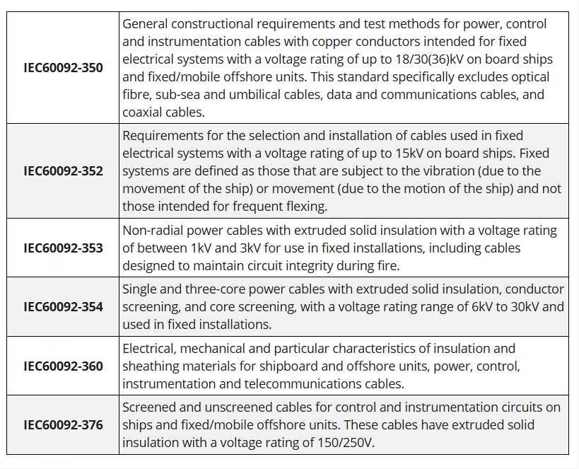
IEC 60092 is the international standard for electrical installations in ships and fixed/mobile marine applications. Ship wiring is covered by various national standards such as BS 6883 (British) and NEK 606 (Norwegian), and subject to third-party accreditations including Lloyd's Register, DNV (Det Norske Veritas), and ABS (American Bureau of Shipping). As an international standard, IEC 60092 covers power and instrumentation cables for use on ships and in mobile marine environments.

What is IEC 60092 Cable?

IEC 60092 cable, marine cable, shipboard cable, offshore cable, BS 6883 cable, NEK 606 cable, BFOU cable, RFOU cable, 657TQ cable, 658TQ cable, fire resistant marine cable, flame retardant cable, ship wiring, offshore platform cable, Lloyd’s Register approved, DNV certified, halogen free cable, LSZH marine cable, MUD resistant cable, IEC 60092-353, IEC 60092-354, IEC 60092-376, SW4 cable, EPR insulated, TCWB armoured, instrumentation cable, control cable, emergency power cable, oil rig cable, Feichun cable
DNV (Det Norske Veritas) is an international accredited registrar and classification society headquartered in Høvik, Norway. As one of the world's leading classification societies, DNV provides certification, verification, and risk management services for the maritime, oil & gas, renewable energy, and other industries. DNV approved cables are electrical cables that have been tested, verified, and certified by DNV to meet stringent safety, quality, and performance standards for use in marine and offshore applications.

What is DNV Approved Cable?

offshore platform cable, drilling platform cable, oil rig cable, FPSO cable, jackup rig cable, semi-submersible cable, drillship cable, offshore wind farm cable, wind turbine cable, subsea cable, underwater cable, shipboard wiring cable, ship electrical cable, naval vessel cable, cruise ship cable, ferry cable, offshore substation cable, offshore power distribution, marine electrical installation