
2kV Type P VFD Cables: Preventing Motor Bearing Damage on Offshore Mud Pumps 2kV Type P 变频器电缆:防止海上泥浆泵电机轴承损伤
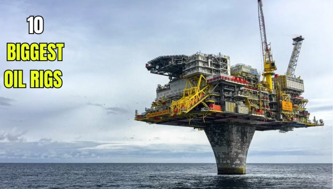
Offshore drilling mud pumps represent some of the most mission-critical equipment on modern drilling platforms. These pumps are driven by variable frequency drive (VFD) systems that optimize power consumption and equipment performance through sophisticated electronic switching, yet this advanced power control technology introduces an insidious threat: VFD-induced electrical discharge machining (EDM) damage to motor bearings, known as fluting. When mud pumps experience unexpected bearing failure due to EDM fluting, unplanned downtime costs platform operators hundreds of thousands of dollars per day in lost production capacity.
The engineering solution to this challenge involves understanding how variable frequency drives generate common-mode voltage and high-frequency current that discharge through motor bearings, then designing 2kV Type P VFD cables with specialized symmetrical grounding architecture and comprehensive electromagnetic shielding to safely contain these currents within the cable and return them to the drive without passing through the motor bearing.
Understanding VFD-Induced Bearing Damage: The Physics of Motor Failure
When variable frequency drives operate AC motors, they use pulse-width modulation (PWM) technology with insulated gate bipolar transistors (IGBTs) to convert pure sine-wave power into a series of high-speed switching DC pulses. This switching pattern creates an asymmetrical output waveform that produces a phenomenon called common-mode voltage: rather than the three phases canceling each other as they would under balanced AC conditions, they now generate a net voltage that couples capacitively onto the motor shaft through parasitic capacitance between stator windings and rotor.
As this shaft voltage accumulates—often reaching 10-20 volts peak within milliseconds—it exceeds the insulating capacity of the bearing grease lubricant. The accumulated charge must discharge, and if no alternative current path exists, electrons arc through the bearing’s rolling elements and races like miniature lightning bolts, each arc creating a fusion crater in the bearing surface. Modern IGBT drives switch at frequencies between 2,000 and 16,000 pulses per second, creating millions of pitting opportunities every hour.
The damage pattern is distinctive. Early EDM damage manifests as frosting—microscopic pitting across the bearing raceway—which progresses to fluting, a washboard-like pattern of concentrated ridges at regular intervals along the bearing race, caused by the VFD’s operating frequency repeating its discharge pattern against the same bearing raceway location. This entire progression from initial frosting to complete bearing failure can occur in as little as 3 months if the bearing is unprotected.
Cable-Level Bearing Protection: The Three-Part Strategy
While motor-level protections (shaft grounding rings and insulated bearings) address one aspect of bearing protection, electrical engineers increasingly recognize that cable-level design provides the first and most effective line of defense by preventing the common-mode voltage from building up in the first place. A properly designed 2kV Type P VFD cable employs three integrated mechanisms:
Strategy 1: Symmetrical Grounding Design (3 Phase + 3 Symmetric Earths)
Standard power cables employ a single ground conductor. For VFD systems, this single ground creates a geometric imbalance that prevents effective cancellation of the electromagnetic fields generated by the three phase conductors. Instead, 2kV Type P VFD cables implement three separate earth conductors, distributed symmetrically in the gaps between the three phase conductors. This 3+3 configuration ensures that electromagnetic fields from adjacent phase conductors cancel each other precisely, dramatically reducing the net magnetic flux that would otherwise induce voltage on the motor shaft.
The physical geometry matters critically. The three earth conductors must be positioned at angles of approximately 120 degrees around the cable circumference, mirroring the three phase conductor positions. This symmetrical arrangement reduces induced voltage imbalances and ensures that common-mode noise returns efficiently to the drive through the ground conductors rather than through the motor shaft.
Strategy 2: Dual-Layer Shielding System (100% EMI Coverage)
The cable must incorporate both aluminum foil tape shielding (continuous coverage) plus tinned copper wire braid shielding (mechanical robustness), engineered together to provide complete electromagnetic interference containment with surface transfer impedance below 50 milliohms at 10 megahertz. This dual-layer approach contains high-frequency noise within the cable while simultaneously providing mechanical protection against crushing and abrasion.
The copper braid component provides the 360-degree terminations at both the drive and motor that are essential for effective shield grounding—without proper 360-degree termination, shield effectiveness degrades dramatically, and the shielding becomes nearly ineffective at high frequencies.
Strategy 3: 2kV Insulation Rating for Voltage Reflection Protection
Standard 600V motor insulation becomes inadequate when connected to a VFD through long cables. Voltage reflection (standing waves) caused by impedance mismatch between the drive output and motor input causes voltage to reflect back from the motor terminals and add constructively when the reflected wave aligns with the forward-traveling pulse. This voltage addition—known as the corona effect—can create voltage peaks at the motor terminal reaching 1.5 to 2 times the drive output voltage. A 600V motor rated for 600V input can experience 900-1200V peaks at its terminals, rapidly degrading or puncturing standard 600V insulation.
The 2kV insulation specification ensures substantial margin above these transient peaks, protecting both motor insulation integrity and the cable itself from accelerated aging from sustained voltage stress.
Technical Parameter Reference: 2kV Type P VFD Cable Specifications
The following specifications represent standard offshore-rated 2kV Type P VFD cables with 3 phase conductors + 3 symmetric earth conductors + overall shielding, suitable for mud pump drive applications. Ampacity values are calculated per IEEE 45/1580 standards at 110°C conductor temperature and 45°C ambient temperature.
| Phase Conductors + Earth Conductors | Phase AWG | Approx. O.D. (mm) | Copper Content (kg/km) | Total Weight (kg/km) | Ampacity @ 110°C (A) |
|---|---|---|---|---|---|
| 3×35mm² + 3×6mm² | 2 AWG | 34.0 – 36.5 | ~1280 | ~2450 | 152 |
| 3×53.5mm² + 3×10mm² | 1/0 AWG | 40.5 – 43.5 | ~1920 | ~3500 | 206 |
| 3×107.0mm² + 3×16mm² | 4/0 AWG | 51.0 – 54.0 | ~3650 | ~6100 | 315 |
| 3×159.0mm² + 3×25mm² | 313 kcmil | 60.5 – 64.0 | ~5400 | ~8600 | 398 |
| 3×227.0mm² + 3×35mm² | 444 kcmil | 68.0 – 72.0 | ~7650 | ~11800 | 480 |
| 3×271.0mm² + 3×35mm² | 535 kcmil | 73.5 – 77.0 | ~8900 | ~13600 | 546 |
Note: Copper content includes phase conductors, symmetric earth conductors, and tinned copper braid shielding. Ampacity assumes skin effect derating of 15-25% is applied during system design. IEEE 1580 Type P specification reference.
Critical Design Specifications for VFD Cable Selection
Symmetrical Earth Conductor Architecture
The earth conductor configuration must be explicitly verified during procurement. Some manufacturers offer “3-core + single ground” designs that provide cost reduction but sacrifice the bearing protection benefits of symmetrical design. Specifications must explicitly require 3 earth conductors distributed symmetrically, typically specified as either bare copper (3×6mm² to 3×16mm² depending on phase conductor size) or insulated with color coding for field verification.
Shield Termination and Continuity Requirements
Proper VFD cable operation requires 360-degree terminations at both the drive and motor, with shield continuity maintained across the entire cable run. Any breaks in shield continuity—from loose gland connections, improper connectors, or damaged shielding—reduce effectiveness dramatically at high frequencies where VFD harmonics concentrate.
Cold Bend and Mechanical Durability (Arctic Grade)
For offshore mud pumps operating in cold marine environments, cables must exceed CSA C22.2 No. 03 cold bend/cold impact specifications (-40°C bend, -35°C impact). Standard cables become brittle at low temperatures; arctic-grade versions maintain flexibility and mechanical integrity across the full temperature range of offshore operations.
Flame Retardancy and Low-Smoke Characteristics
System-Level Integration: Beyond Cable Selection
While proper VFD cable design provides the foundation for bearing protection, electrical engineers must implement a complete protection strategy. The most effective approach combines symmetrical shielded VFD cables with shaft grounding rings on the motor and, for large motors exceeding 100 horsepower, either insulated bearings or hybrid bearing designs at the opposite end from the grounding ring.
Additionally, output filtering through dV/dt filters or sine-wave filters reduces the steepness of voltage rising edges from the drive transistor switching, lowering the rate of common-mode voltage change that couples into the motor shaft capacitively. Cable length also matters: VFD cables longer than approximately 150 meters create capacitive effects that can increase common-mode voltage, justifying the installation of output reactors or line reactors for longer cable runs.
Procurement and Specification Best Practices
When procuring 2kV Type P VFD cables for offshore mud pump applications, electrical specifications must explicitly address the following points to prevent cost-cutting substitutions:
First, specify 3 symmetric earth conductors explicitly, not “1 ground + 2 optional earths”. The word “optional” invites cost reduction at the expense of bearing protection.
Second, require detailed shield specifications: both aluminum foil tape coverage percentage (specify 100%) and tinned copper braid mesh size or coverage percentage (60-100% typically). Request surface transfer impedance data demonstrating values below 50 milliohms at 10 MHz.
Third, verify double certification: cables should be dual certified to both IEEE 1580 Type P and UL 1309/CSA C22.2 No. 245 Type X110 standards, ensuring compliance with both North American and international offshore specifications.
Fourth, confirm cold temperature performance documentation showing compliance with CSA C22.2 No. 03 (-40°C bend, -35°C impact) standards before equipment shipment to arctic or subarctic drilling operations.
Conclusion: The Business Case for Proper VFD Cable Specification
Motor bearing failure on offshore mud pumps is not an acceptable operational risk. The engineering solution is well understood: properly designed 2kV Type P VFD cables with symmetrical grounding, comprehensive shielding, and appropriate insulation rating work in concert with motor-level protections to virtually eliminate EDM fluting risk.
The cost of specifying premium VFD cables represents a small fraction of the catastrophic costs associated with unplanned platform downtime. Platform operators have learned through painful experience that investing in proper cable specification during design phase prevents far larger expenditures during operations.
Ampacity values presented above assume standard IEEE 45 calculation conditions: 110°C conductor temperature, 45°C ambient temperature, and single-cable free-air installation. VFD systems typically experience skin effect at high switching frequencies, reducing effective conductor cross-section. Electrical engineers should apply 15-25% derating when sizing cables for actual duty cycles. Shaft voltage monitoring using oscilloscope measurement with 100 MHz bandwidth or higher should be performed after cable installation to verify that shaft voltage remains below 5V peak (10V peak-to-peak) under operating conditions.
Authoritative References and Sources
Technical Consultation & Sales Inquiries:
📧 Email: [email protected]
📞 WhatsApp/Phone: +86 13855123218
Authorized supplier of 2kV IEEE 1580 Type P VFD cables for offshore drilling mud pump systems, production platforms, and international oil and gas installations. Comprehensive bearing protection engineering support and technical consultation.


