
Complete Technical Guide for Torsional Power Cables
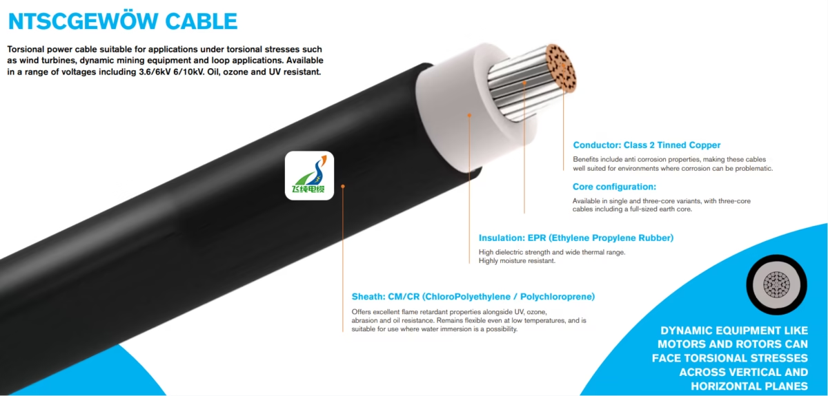
What is NTSCGEWÖW Cable?
A comprehensive technical guide to medium voltage torsional power cables engineered for wind turbines, dynamic mining equipment, and loop applications requiring exceptional rotational stress resistance.
1. Cable Nomenclature and Purpose
The NTSCGEWÖW cable (also written as NTSCGEWOEW when substituting the umlaut for ‘OE’) represents a specialized category of medium voltage power cables engineered specifically to withstand torsional stresses inherent in dynamic industrial applications. This cable designation follows the standardized German DIN VDE nomenclature system, with each letter indicating specific construction characteristics optimized for rotational stress environments.
1.1 Primary Purpose and Applications
The NTSCGEWÖW cable serves as the primary power distribution solution for applications where equipment undergoes continuous rotational movement, creating torsional stresses that would damage conventional cables. The cable is specifically engineered for loop applications in wind turbines where the nacelle rotates to track wind direction, as well as for dynamic mining equipment including draglines, bucket-wheel excavators, and continuous miners that require power supply during operational movement.
According to industry specifications from Feichun Reeling Cable solutions, these cables are designed to withstand torsional stresses up to ±100°/m, making them suitable for the most demanding rotational applications. The construction materials provide robust protection against environmental challenges including UV radiation, ozone exposure, oil contamination, and abrasion typically encountered in renewable energy and mining installations.
2. Technical Specifications and Parameters
2.1 Electrical Characteristics
| Parameter | 3.6/6 kV Rating | 6/10 kV Rating | Standard Reference |
|---|---|---|---|
| Rated Voltage Uo/U | 3.6/6 kV | 6/10 kV | DIN VDE 0276 |
| Maximum System Voltage Um | 7.2 kV | 12 kV | IEC 60502-2 |
| AC Test Voltage (5 min) | 12.5 kV | 17 kV | DIN VDE 0276-620 |
| Insulation Resistance | ≥100 MΩ·km at 20°C | IEC 60502-2 | |
| Conductor Resistance | Per IEC 60228 Class 2 | IEC 60228 | |
2.2 Thermal Performance Parameters
| Operating Condition | Temperature | Notes |
|---|---|---|
| Maximum Continuous Operating | 90°C | Conductor temperature |
| Short Circuit Temperature | 250°C | Maximum 5 seconds duration |
| Minimum Operating Temperature | -40°C | EPR maintains flexibility |
| Installation Temperature Range | -25°C to +50°C | Without preheating |
| Storage Temperature | -40°C to +50°C | Protected from UV |
2.3 Mechanical and Torsional Parameters
The critical differentiating characteristic of NTSCGEWÖW cables lies in their torsional performance. Industry testing protocols, as documented by port and crane cable specialists, establish standardized methods for evaluating cable performance under rotational stress conditions.
| Mechanical Parameter | Specification | Test Condition |
|---|---|---|
| Torsion Resistance | ±100°/m | Per 10m cable length |
| Torsion Cycle Rating (Normal Temp) | ≥10,000 cycles | At 30°C ambient |
| Torsion Cycle Rating (Low Temp) | ≥2,000 cycles | At -40°C ambient |
| Minimum Bending Radius (Fixed) | 6 × OD | Single movement |
| Minimum Bending Radius (Dynamic) | 8 × OD | Repeated flexing |
| Maximum Tensile Load | 15 N/mm² | On conductor cross-section |
Torsion Testing Protocol: Standard industry testing involves twisting a 10-meter cable sample 4 × 360° clockwise then 4 × 360° counterclockwise (total ±1440°) at temperatures as low as -40°C. Cables must complete a minimum of 5,000 complete cycles to simulate a 20-year operational lifetime in wind turbine applications.
2.4 Cross-Sectional Availability
| Cross-Section (mm²) | Approx. OD Single Core (mm) | Approx. OD 3-Core (mm) | Approx. Weight 3-Core (kg/km) |
|---|---|---|---|
| 25 | 22-24 | 48-52 | 2,400 |
| 35 | 24-26 | 52-56 | 2,850 |
| 50 | 26-28 | 56-60 | 3,450 |
| 70 | 28-31 | 60-66 | 4,200 |
| 95 | 31-34 | 66-72 | 5,100 |
| 120 | 34-37 | 72-78 | 6,100 |
| 150 | 37-40 | 78-84 | 7,200 |
| 185 | 40-44 | 84-92 | 8,500 |
| 240 | 44-48 | 92-100 | 10,200 |
3. Material Structure and Construction
The NTSCGEWÖW cable construction represents a carefully engineered assembly where each layer contributes to the cable’s exceptional torsional performance while maintaining electrical integrity under demanding operational conditions.
Conductor
Class 2 stranded tinned copper per IEC 60228. Tinning provides anti-corrosion properties essential for humid environments and offshore installations. The stranded construction ensures flexibility during torsional movement.
Conductor Screen
Semi-conductive compound layer ensuring uniform electric field distribution at the conductor-insulation interface. Prevents partial discharge and extends insulation life.
Insulation (EPR)
Ethylene Propylene Rubber providing high dielectric strength (≥12.5 kV/mm), excellent moisture resistance, and wide thermal operating range (-40°C to +90°C). EPR maintains flexibility at low temperatures critical for torsional applications.
Insulation Screen
Semi-conductive layer ensuring controlled electric field termination at the insulation surface. Essential for reliable partial discharge-free operation in medium voltage applications.
Metallic Screen
Concentric copper wire screen providing electromagnetic shielding and earth fault current path. Designed to accommodate torsional movement without wire breakage.
Inner Sheath
Rubber-based bedding compound protecting screen assembly and providing foundation for anti-torsion reinforcement elements.
Anti-Torsion Reinforcement
Woven textile braid (typically Kevlar or high-tenacity polyester) providing structural integrity during rotational stress. This critical element prevents conductor corkscrewing and maintains cable geometry.
Outer Sheath (CM/CR)
ChloroPolyethylene (CM) or Polychloroprene (CR) compound offering excellent flame retardancy, UV resistance, ozone resistance, abrasion resistance, and oil resistance. Maintains flexibility at low temperatures and withstands water immersion.
3.1 EPR Insulation Technical Properties
| Property | Value | Test Method |
|---|---|---|
| Dielectric Strength | ≥12.5 kV/mm | IEC 60502-2 |
| Volume Resistivity | ≥10¹⁴ Ω·cm | IEC 60093 |
| Dielectric Constant (εr) | 2.8 – 3.2 | IEC 60250 |
| Tensile Strength | ≥6.5 N/mm² | IEC 60811 |
| Elongation at Break | ≥200% | IEC 60811 |
| Ozone Resistance | No cracking (72h @ 50 pphm) | IEC 60811-403 |
3.2 Outer Sheath Properties (CM/CR Compound)
| Property | Value | Test Method |
|---|---|---|
| Tensile Strength | ≥10 N/mm² | IEC 60811 |
| Elongation at Break | ≥300% | IEC 60811 |
| Shore A Hardness | 65 ± 5 | ISO 868 |
| Abrasion Resistance | ≤150 mm³ | DIN 53516 |
| Oil Resistance (IRM 902, 70°C/168h) | Mass change ≤25% | IEC 60811-404 |
| Flame Retardancy | Pass | IEC 60332-1-2 |
4. Standards Compliance
NTSCGEWÖW cables are manufactured in accordance with multiple international and regional standards, ensuring quality, safety, and performance verification across global markets.
| Standard | Description | Application Area |
|---|---|---|
| DIN VDE 0250-813 | German standard for medium voltage reeling cables | Primary manufacturing standard |
| IEC 60502-2 | Power cables rated 6kV to 30kV | Electrical testing requirements |
| IEC 60228 | Conductors of insulated cables | Conductor specifications |
| IEC 60332-1-2 | Flame propagation test – single cable | Fire safety compliance |
| IEC 60811 | Non-electrical tests for cables | Mechanical property testing |
| EN 50525 | Electric cables – Low voltage flexible cables | Flexible cable requirements |
5. Application Scenarios
The NTSCGEWÖW cable finds application across diverse industries where equipment operation creates rotational stress on power cables. According to technical resources from mining cable specialists, proper cable selection for torsional applications directly impacts operational reliability and maintenance costs.
Wind Turbine Loop Cables
Primary application for NTSCGEWÖW cables. The nacelle housing the generator must rotate to track wind direction, creating continuous torsional stress on power cables connecting the generator to the tower transformer. Loop cables must accommodate up to four full rotations in either direction before yaw control returns the nacelle to neutral position.
Mining Trailing Equipment
Dragline excavators, bucket-wheel reclaimers, and continuous mining machines require power supply cables that accommodate equipment rotation during operational cycles. The robust construction resists abrasion and oil contamination typical in mining environments.
Port Crane Systems
Ship-to-shore cranes, rubber-tyred gantry cranes, and automated stacking cranes incorporate rotational movements that create torsional cable stress. Resources from industrial cable specialists confirm the importance of proper torsion-rated cables for heavy material handling equipment.
Renewable Energy Installations
Beyond wind turbines, solar tracking systems and wave energy converters incorporate rotational mechanisms requiring torsion-resistant power cables. The UV and ozone resistance of the CM/CR sheath provides long-term outdoor durability.
6. Safety Thresholds and Critical Limits
⚠ Critical Safety Parameters
Exceeding these thresholds may result in cable damage, equipment failure, or safety hazards. All installations must incorporate appropriate safety margins and monitoring systems.
| Parameter | Maximum Safe Value | Consequence of Exceeding |
|---|---|---|
| Conductor Temperature (Continuous) | 90°C | EPR degradation, reduced insulation life |
| Short Circuit Temperature | 250°C (max 5 sec) | Insulation failure, potential fire hazard |
| Torsion Angle | ±100°/m | Conductor fatigue, screen damage |
| Minimum Bending Radius (Dynamic) | 8 × OD | Conductor breakage, insulation cracking |
| Maximum Tensile Load | 15 N/mm² | Conductor elongation, structural damage |
| Operating Temperature (Minimum) | -40°C | Sheath brittleness, reduced flexibility |
6.1 Installation Temperature Considerations
Cable installation at temperatures below -25°C requires preheating procedures to maintain material flexibility. The EPR insulation and CR sheath maintain functional flexibility down to -40°C during operation, but installation handling at extreme low temperatures risks mechanical damage.
7. Installation Precautions and Best Practices
✓ Pre-Installation Verification
Perform insulation resistance testing and visual inspection before installation. Verify cable routing accommodates maximum anticipated torsional movement with appropriate safety margin. Confirm ambient temperature is within installation limits.
7.1 Loop Cable Installation (Wind Turbines)
Loop cables require precise installation to ensure reliable operation throughout the turbine’s service life. The free-hanging loop must be sized to accommodate the maximum rotation angle without exceeding the cable’s torsion rating. Industry best practice recommends installing the loop cable at the nacelle’s neutral position and verifying clearance throughout the full rotation range before commissioning.
Cable support systems must allow free movement without creating stress concentration points. Avoid rigid clamps or sharp edges that could damage the outer sheath during rotation. Use smooth-radius guides and flexible support brackets specifically designed for torsional cable applications.
7.2 Trailing Cable Installation (Mining)
For trailing applications on mobile mining equipment, cable length must accommodate the full travel distance plus additional length for torsional accommodation. The cable should never be under tension during normal operation. Trailing cable reels should incorporate torque limiting mechanisms to prevent over-tensioning during cable retrieval.
7.3 General Installation Guidelines
Observe minimum bending radius requirements at all installation points. Use appropriate cable pulling equipment with tension monitoring for long installations. Apply manufacturer-approved lubricant for conduit or duct installations. Install cable route markers and torsion monitoring systems where applicable.
⚠ Torsion Monitoring
For critical applications, install torsion cycle counters or rotation sensors to track cumulative torsional stress. Establish maintenance inspection schedules based on actual operational cycles rather than calendar intervals alone. Wind turbine loop cables typically require inspection when approaching 70% of rated torsion cycles.
8. Comparison with Alternative Cable Types
| Parameter | NTSCGEWÖW | Standard XLPE/PVC Cable | Standard Reeling Cable |
|---|---|---|---|
| Torsion Resistance | ±100°/m | Not rated | ±30-50°/m typical |
| Temperature Range | -40°C to +90°C | -15°C to +90°C | -25°C to +60°C |
| Oil Resistance | Excellent | Limited (PVC degrades) | Good |
| UV Resistance | Excellent | Moderate (PVC fading) | Good |
| Ozone Resistance | Excellent | Limited | Good |
| Minimum Bending Radius | 6 × OD (fixed) | 12-15 × OD | 6-8 × OD |
| Typical Application | Wind turbines, mining | Fixed installations | Crane reeling drums |
9. Frequently Asked Questions
Request Technical Consultation
Our engineering team at Anhui Feichun Special Cable Co., Ltd. provides expert guidance on NTSCGEWÖW cable specification, custom manufacturing solutions, and technical support for wind energy, mining, and industrial torsional cable applications.
References and Technical Resources
This technical guide references information from multiple authoritative industry sources. For additional technical information on specific applications:
For reeling and festoon cable systems: Feichun Reeling Cable Solutions
For port and crane cable applications: Specialized Port Machinery Cables
For mining industry cable specifications: Australian Mining Cable Standards
For South American industrial applications: Chile Industrial Cable Resources
For additional Feichun product information: Feichun Cable Main Site
External standard references: VDE Association, International Electrotechnical Commission
Wind energy industry resources: Windpower Engineering, Renewable Energy World


