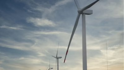
Medium Voltage XLPE Power Cable 8.7/15 (17.5) kV Technical Guide

Wind Turbine Cable Technology
8.7/15 (17.5) kV
Understanding Wind Turbine Cable Systems
Wind turbine cables represent a critical component in renewable energy infrastructure, serving as the vital link between mechanical energy generation and electrical power distribution. These specialized medium voltage cables are engineered to withstand the unique environmental challenges present in wind energy applications, including constant mechanical stress, temperature variations, and exposure to harsh weather conditions.
The cables discussed in this technical overview conform to multiple international standards, including the harmonized European standard HD 620 S3:2023, the International Electrotechnical Commission standard IEC 60502-2:2014, British Standard BS 7870-4.10:2011, and German standard DIN VDE 0276-620:2018. This multi-standard compliance ensures broad compatibility and adherence to stringent safety requirements across different jurisdictions and applications.
Wind Turbine Architecture
Modern wind turbines are sophisticated electromechanical systems consisting of multiple integrated components working in harmony to convert kinetic wind energy into electrical power. Understanding these components provides essential context for appreciating the critical role of specialized cabling systems.
Rotor Blades
Aerodynamic structures that capture wind energy and convert it into rotational motion through carefully engineered airfoil profiles.
Pitch Control Unit
Adjusts blade angles dynamically to control rotation speed and optimize power output across varying wind conditions.
Hub
Central connection point where rotor blades attach, transmitting captured rotational energy to the drive train.
Brake System
Safety mechanism enabling emergency shutdown and controlled stopping during maintenance procedures or adverse conditions.
Gearbox Transmission
Increases low-speed shaft rotation to high-speed operation necessary for efficient generator performance.
Climate Sensors & Aviation Light
Environmental monitoring systems and FAA-compliant lighting ensuring operational safety and aircraft collision avoidance.
Nacelle
Weatherproof housing containing generator, gearbox, and control systems, protecting critical electrical components.
Generator
Converts mechanical rotational energy from the drive train into three-phase alternating current electrical energy.
Yaw Drive
Rotates the nacelle assembly to maintain optimal alignment with prevailing wind direction for maximum energy capture.
Cable System
Transfers generated electrical power from nacelle-mounted generator down through tower structure to ground-level distribution equipment.
Access System
Internal ladder or elevator system providing maintenance personnel safe access to nacelle and rotor hub components.
Tower Structure
Structural support elevating rotor assembly to optimal height for accessing consistent, high-velocity wind resources.
Foundation
Engineered concrete base anchoring tower securely to ground, ensuring structural stability under dynamic loading conditions.
Transformer Station
Converts generator output to transmission-suitable voltage levels for integration with electrical power grid infrastructure.
Technical Cable Specifications
Conductor Configuration
The cables feature circular stranded and compacted copper conductors manufactured to Class 2 specifications, ensuring optimal current-carrying capacity and mechanical flexibility. The compacted construction (RMC designation) reduces overall cable diameter while maintaining equivalent electrical performance compared to non-compacted designs, resulting in improved space utilization within cable ducts and reduced installation costs.
Operating Conditions
These cables are designed for installation in both underground and aerial configurations. For underground installations, the recommended burial depth is 0.7 meters with ground temperature assumed at 20°C and soil thermal resistivity of 1.0 K·m/W. Aerial installations require protection from direct solar radiation with ambient temperature considerations at 25°C. These standardized conditions align with IEC 60287 series standards for current rating calculations.
Physical & Mechanical Characteristics
The following table presents comprehensive dimensional and mechanical data for the complete cable range, from 35 mm² to 1000 mm² conductor cross-sections. These parameters are critical for proper cable selection, installation planning, and mechanical load calculations.
| Conductor Size | Conductor Ø | Insulation Thickness | Ø Over Insulation | Screen Area | Cable Ø (De) | Cable Weight | Max Pulling Force | Min Bend Radius |
|---|---|---|---|---|---|---|---|---|
| 1×35 RMC | 7.0 mm | 4.5 mm | 17.2 mm | 16 mm² | 25.9 mm | 920 kg/km | 1.75 kN | 0.39 m |
| 1×50 RMC | 8.25 mm | 4.5 mm | 18.5 mm | 16 mm² | 27.1 mm | 1060 kg/km | 2.5 kN | 0.41 m |
| 1×70 RMC | 9.6 mm | 4.5 mm | 19.8 mm | 25 mm² | 28.5 mm | 1370 kg/km | 3.5 kN | 0.43 m |
| 1×95 RMC | 11.5 mm | 4.5 mm | 21.7 mm | 35 mm² | 30.4 mm | 1740 kg/km | 4.75 kN | 0.46 m |
| 1×120 RMC | 12.9 mm | 4.5 mm | 23.1 mm | 50 mm² | 31.8 mm | 2140 kg/km | 6 kN | 0.48 m |
| 1×150 RMC | 14.5 mm | 4.5 mm | 24.7 mm | 50 mm² | 33.4 mm | 2430 kg/km | 7.5 kN | 0.50 m |
| 1×185 RMC | 16.0 mm | 4.5 mm | 26.2 mm | 50 mm² | 34.9 mm | 2790 kg/km | 9.25 kN | 0.52 m |
| 1×240 RMC | 18.5 mm | 4.5 mm | 28.7 mm | 50 mm² | 37.4 mm | 3350 kg/km | 12 kN | 0.56 m |
| 1×300 RMC | 20.5 mm | 4.5 mm | 30.7 mm | 50 mm² | 39.4 mm | 3940 kg/km | 15 kN | 0.59 m |
| 1×400 RMC | 23.5 mm | 4.5 mm | 33.7 mm | 50 mm² | 42.4 mm | 4810 kg/km | 20 kN | 0.64 m |
| 1×500 RMC | 26.5 mm | 4.5 mm | 37.2 mm | 50 mm² | 46.1 mm | 5920 kg/km | 25 kN | 0.69 m |
| 1×630 RMC | 30.3 mm | 4.5 mm | 41.3 mm | 50 mm² | 50.3 mm | 7290 kg/km | 31.5 kN | 0.75 m |
| 1×800 RMC | 34.6 mm | 4.5 mm | 46.0 mm | 50 mm² | 55.4 mm | 9010 kg/km | 40 kN | 0.83 m |
| 1×1000 RMC | 38.2 mm | 4.5 mm | 49.6 mm | 50 mm² | 59.2 mm | 10930 kg/km | 50 kN | 0.89 m |
Note: RMC (Circular Stranded Compacted Conductor, Class 2) configuration provides optimal balance between flexibility and current-carrying capacity. The minimum bending radius values are specified for installation conditions and must be strictly observed to prevent insulation damage.
Electrical Performance Data
Accurate electrical parameters are essential for power system design, protection coordination, and thermal analysis. The data presented reflects standardized test conditions with conductor resistance measured at 20°C (DC) and 90°C (AC), representing ambient and operating temperatures respectively. Metallic screen resistance is measured at 20°C (DC) and 80°C (AC).
| Size | RDC 20°C (Ω/km) | RAC 90°C (Ω/km) | Screen R (Ω/km) | Field Stress (kV/mm) | R0 (Ω/km) | X0 (Ω/km) | Capacitance (µF/km) | XC (Ω/km) | IC (A/km) |
|---|---|---|---|---|---|---|---|---|---|
| 1×35/16 | 0.524 | 0.668 | 1.12/1.38 | 2.84/1.32 | 2.05 | 0.082 | 0.17 | 19.1 | 0.46 |
| 1×50/16 | 0.387 | 0.494 | 1.12/1.38 | 2.72/1.37 | 1.88 | 0.075 | 0.19 | 17.2 | 0.51 |
| 1×70/25 | 0.268 | 0.342 | 0.72/0.89 | 2.63/1.41 | 1.23 | 0.070 | 0.20 | 15.6 | 0.56 |
| 1×95/35 | 0.193 | 0.247 | 0.51/0.63 | 2.52/1.45 | 0.88 | 0.063 | 0.23 | 13.7 | 0.63 |
| 1×120/50 | 0.153 | 0.196 | 0.36/0.44 | 2.46/1.48 | 0.64 | 0.060 | 0.25 | 12.7 | 0.69 |
| 1×150/50 | 0.124 | 0.159 | 0.36/0.44 | 2.41/1.51 | 0.60 | 0.056 | 0.27 | 11.6 | 0.75 |
| 1×185/50 | 0.0991 | 0.128 | 0.36/0.44 | 2.37/1.54 | 0.57 | 0.053 | 0.30 | 10.8 | 0.81 |
| 1×240/50 | 0.0754 | 0.0979 | 0.36/0.44 | 2.31/1.57 | 0.54 | 0.049 | 0.33 | 9.6 | 0.90 |
| 1×300/50 | 0.0601 | 0.0789 | 0.36/0.44 | 2.27/1.59 | 0.52 | 0.047 | 0.36 | 8.9 | 0.98 |
| 1×400/50 | 0.0470 | 0.0630 | 0.36/0.44 | 2.23/1.62 | 0.51 | 0.043 | 0.40 | 7.9 | 1.10 |
| 1×500/50 | 0.0366 | 0.0506 | 0.36/0.44 | 2.17/1.63 | 0.49 | 0.042 | 0.44 | 7.2 | 1.21 |
| 1×630/50 | 0.0283 | 0.0412 | 0.36/0.44 | 2.13/1.65 | 0.48 | 0.040 | 0.50 | 6.4 | 1.37 |
| 1×800/50 | 0.0221 | 0.0344 | 0.36/0.44 | 2.1/1.67 | 0.48 | 0.038 | 0.57 | 5.6 | 1.55 |
Current Carrying Capacity
Current ratings are calculated according to IEC 60287 methodology under specified installation conditions. The values represent continuous current carrying capacity for different configurations including ground burial (flat and trefoil formation) and aerial installation (flat and trefoil formation), with variations for single point bonding (SPB), cross bonding (CB), and both ends bonded (BE) metallic screen configurations.
| Conductor Size | Short Circuit Capacity (kA/s) | Ground – Flat | Ground – Trefoil | Air – Flat | Air – Trefoil | ||||
|---|---|---|---|---|---|---|---|---|---|
| BE | SPB/CB | BE | SPB/CB | BE | SPB/CB | BE | SPB/CB | ||
| 1×35/16 | 5.0/3.7 | 243 A | 245 A | 230 A | 230 A | 246 A | 248 A | 210 A | 211 A |
| 1×50/16 | 7.2/3.7 | 288 A | 291 A | 273 A | 273 A | 296 A | 298 A | 252 A | 253 A |
| 1×70/25 | 10.0/5.3 | 348 A | 356 A | 333 A | 334 A | 363 A | 370 A | 311 A | 313 A |
| 1×95/35 | 13.6/7.1 | 413 A | 430 A | 400 A | 403 A | 438 A | 454 A | 380 A | 383 A |
| 1×120/50 | 17.2/9.8 | 456 A | 491 A | 454 A | 460 A | 492 A | 523 A | 435 A | 440 A |
| 1×150/50 | 21.5/9.8 | 505 A | 554 A | 510 A | 518 A | 555 A | 598 A | 495 A | 502 A |
| 1×185/50 | 26.5/9.8 | 560 A | 628 A | 575 A | 586 A | 625 A | 685 A | 564 A | 574 A |
| 1×240/50 | 34.3/9.8 | 634 A | 733 A | 667 A | 684 A | 725 A | 814 A | 665 A | 681 A |
| 1×300/50 | 42.9/9.8 | 697 A | 830 A | 750 A | 773 A | 812 A | 935 A | 757 A | 779 A |
| 1×400/50 | 57.2/9.8 | 773 A | 953 A | 849 A | 882 A | 920 A | 1093 A | 874 A | 906 A |
| 1×500/50 | 71.5/9.8 | 850 A | 1088 A | 957 A | 1002 A | 1034 A | 1270 A | 1003 A | 1047 A |
Configuration Notes: Trefoil formation represents three cables arranged in triangular configuration with spacing equal to cable diameter (De). Flat formation represents cables arranged linearly with spacing De (ground) or 2×De (air). SPB (Single Point Bonded) and CB (Cross Bonded) configurations reduce metallic screen losses compared to BE (Both Ends) bonding, resulting in higher current ratings.
Application & Purpose in Wind Energy Systems
These medium voltage XLPE cables serve as the critical power transmission link within wind turbine installations, conducting generated electrical energy from the nacelle-mounted generator through the tower structure to ground-level distribution equipment. The cables must withstand continuous flexing due to yaw movements, temperature cycling from ambient to full load conditions, and potential exposure to moisture infiltration.
Wind farm cable networks typically employ these cables in three primary configurations. Tower cables run vertically through the turbine structure, subjected to minimal mechanical stress but requiring adequate ampacity for full generator output. Inter-array cables connect multiple turbines within the wind farm, often installed underground in dedicated trenches or ducts. Export cables transmit consolidated power from the wind farm collection point to grid connection substations, frequently covering significant distances.
The multi-standard compliance (HD 620, IEC 60502-2, BS 7870, DIN VDE 0276-620) ensures these cables meet harmonized European requirements while maintaining compatibility with international specifications. This broad acceptance facilitates use in diverse geographic markets and regulatory environments, from offshore installations in the North Sea to onshore wind farms in developing markets.
Key Material Characteristics
Cross-Linked Polyethylene (XLPE) Insulation
XLPE insulation technology represents the industry standard for medium voltage power cables due to its superior electrical, thermal, and mechanical properties. The cross-linking process creates three-dimensional molecular bonds that enhance thermal stability, allowing continuous operation at 90°C conductor temperature with emergency overload capability to 130°C. XLPE exhibits excellent dielectric strength with low dielectric losses, contributing to improved energy efficiency and reduced heat generation during operation.
Compared to traditional paper-insulated lead-covered (PILC) cables, XLPE technology eliminates oil impregnation requirements, reducing environmental concerns and maintenance needs. The solid dielectric construction provides superior moisture resistance, critical for underground installations where water ingress represents a primary failure mechanism. XLPE cables demonstrate exceptional resistance to partial discharge degradation, ensuring extended service life in demanding applications.
Copper Conductor Benefits
Copper conductors provide optimal electrical conductivity (58 MS/m at 20°C), second only to silver among practical conductor materials. The Class 2 stranded construction balances current-carrying capacity with mechanical flexibility, essential for installation through tower cable trays and around equipment. Compacted strand design (RMC designation) reduces void spaces between individual wires, minimizing oxidation potential and improving current distribution across the conductor cross-section.
The circular stranded configuration ensures uniform current density distribution, reducing skin effect losses at power frequency and improving overall efficiency. Copper’s excellent thermal conductivity (401 W/m·K) facilitates efficient heat dissipation from the conductor core through the insulation system, critical for achieving rated current capacity under continuous loading conditions.
Metallic Screen Functionality
The metallic screen layer serves multiple critical functions in medium voltage cable design. Electrically, the screen provides a uniform cylindrical equipotential surface around the insulation, controlling radial electrical field distribution and preventing discharge inception at the insulation outer surface. The screen also provides a low-impedance fault current return path, enabling rapid fault detection and protection system operation.
Mechanically, the screen protects the sensitive insulation from external mechanical damage during installation and service. The screen configuration (copper wire or tape) affects cable flexibility, with wire screens providing superior bending characteristics for applications requiring frequent movement or tight radius bends.
Industry Resources & Related Information
For comprehensive information on specialized cable applications and industry best practices, the following resources provide valuable technical guidance and product specifications across various industrial sectors:
These industry partners provide specialized expertise in mobile cable applications, mining industry solutions, overhead crane installations, and custom cable design services. Their technical documentation and application guides complement the information presented here, offering deeper insights into specific installation scenarios and operational requirements.
Contact Anhui Feichun Special Cable Co., Ltd.
For technical inquiries, quotations, or project-specific cable specifications, please contact our engineering team through any of the following channels:
Our engineering team provides comprehensive support including cable selection guidance, installation recommendations, compliance verification, and custom cable design for specialized applications. We maintain extensive technical documentation and can provide detailed test reports, quality certifications, and compliance declarations for all standard and custom cable products.
Conclusion
Medium voltage XLPE cables conforming to HD 620 S3:2023, IEC 60502-2:2014, BS 7870-4.10:2011, and DIN VDE 0276-620:2018 standards represent the optimal solution for wind turbine power transmission applications. The combination of XLPE insulation technology, copper conductor efficiency, and robust mechanical design ensures reliable operation under the demanding conditions characteristic of renewable energy installations.
Anhui Feichun Special Cable Co., Ltd. manufactures these cables to the highest quality standards, employing advanced production techniques and rigorous quality control procedures. Our commitment to technical excellence and customer support ensures that every cable meets or exceeds specified performance requirements, contributing to the reliable operation of wind energy infrastructure worldwide.
As the global renewable energy sector continues its rapid expansion, the importance of reliable electrical infrastructure becomes increasingly critical. These specialized cables form an integral component of that infrastructure, quietly enabling the transformation of wind energy into clean electrical power for millions of consumers worldwide.