
A comprehensive dimension guide to understanding the exact width and thickness specifications of (N)TSFLCGEWÖU 4×120 0.6/1kV shielded flat trailing cables used in overhead cranes, gantry systems, and variable-frequency-drive equipment. Covers DIN VDE 0250-813 dimensional standards, tolerance windows, festoon system compatibility, equipment integration requirements for material handling systems, manufacturing variations across suppliers, and precise field measurement procedures ensuring proper fit and safe operation.
— 理解(N)TSFLCGEWÖU 4×120 0.6/1kV屏蔽型扁电缆精确宽度和厚度规格的综合尺寸指南。
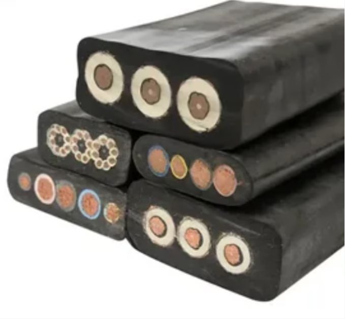
What is the Width and Thickness of (N)TSFLCGEWÖU 4×120 0.6/1kV Shielded Flat Cable?
A comprehensive dimension guide to understanding the exact width and thickness specifications of (N)TSFLCGEWÖU 4×120 0.6/1kV shielded flat trailing cables used in overhead cranes, gantry systems, and variable-frequency-drive equipment. Covers DIN VDE 0250-813 dimensional standards, tolerance windows, festoon system compatibility, equipment integration requirements for material handling systems, manufacturing variations across suppliers, and precise field measurement procedures ensuring proper fit and safe operation. — 理解(N)TSFLCGEWÖU 4×120 0.6/1kV屏蔽型扁电缆精确宽度和厚度规格的综合尺寸指南。
1. Direct Answer for Engineering Specs: Width and Thickness Overview 工程规格直接答案:宽度和厚度概述
The nominal width of a (N)TSFLCGEWÖU 4×120 0.6/1kV shielded flat trailing cable is approximately 91 mm (3.58 inches), with a tolerance window of ±3.5 mm producing a permissible range of 87.5–94.5 mm. The nominal thickness is approximately 27.5 mm (1.08 inches), with a tolerance window of ±1.5 mm producing a permissible range of 26.0–29.0 mm. The approximate total weight of this cable is 8,200 kg/km (5,500 lbs/1000 ft), with copper weight approximately 5,250 kg/km. It features four 120 mm² main power conductors rated for 321 amperes continuous operation at 30°C ambient, supplemented by individual copper braid shielding on each conductor for electromagnetic compatibility (EMC) with variable-frequency drives and other sensitive equipment.
The distinction between width and thickness for flat cables differs fundamentally from round cable specifications because flat cables do not have a single outer diameter. Instead, engineers must manage two dimensions simultaneously, and these dimensions directly determine whether the cable will fit into festoon track systems, contact shoe assemblies, and guidance rail configurations commonly deployed in overhead crane systems and automated material handling equipment.
2. Why Flat Cable Dimensions Matter Differently Than Round Cables 扁电缆尺寸与圆形电缆的区别
Round cables (like the Type SHD-GC and (N)TSCGEWÖU models we discussed in previous guides) have a single outer diameter that determines whether they fit in reel bores, conduit systems, and terminal connectors. Flat cables present a more complex compatibility challenge because they have both width and thickness, and different equipment systems place different constraints on these dimensions. An overhead crane’s festoon track system might accommodate a cable 95 mm wide and 30 mm thick, but the contact shoe assembly that extracts current from the cable might require a maximum thickness of 28 mm to seat properly and establish reliable electrical contact.
This dual-dimension requirement means that flat cable procurement requires more careful engineering coordination with equipment manufacturers than round cable selection. You cannot specify only the conductor size (4×120 mm²) and voltage rating (0.6/1 kV) and assume compatibility. You must explicitly coordinate width and thickness specifications with the festoon system designer to ensure proper fit across all integration points: the cable guide track bore, the contact shoe clearance, the support roller dimensions, and the winding geometry on cable reels.
Critical Engineering Principle 关键工程原理: Flat cables serving overhead crane and material handling systems operate in an integrated ecosystem. The festoon track, contact shoes, support rollers, guide blocks, and cable reel are all engineered as an assembly, with dimensional assumptions about cable width and thickness built into every component. If a replacement cable’s width or thickness falls outside the original design window, the entire system may malfunction. A cable that is too thick will not fit in the contact shoe assembly; a cable that is too wide will bind against guide blocks; a cable that is too thin will slip within the track bore. Unlike round cables where a small diameter variation might be merely inconvenient, flat cable dimension mismatches can be safety-critical.
3. DIN VDE 0250-813: Dimensional Framework for Flat Trailing Cables DIN VDE 0250-813:扁电缆尺寸框架
The DIN VDE 0250-813 standard, harmonized with IEC 60811 and other international standards, establishes dimensional specifications for flat trailing cables used in industrial applications including overhead cranes, gantry systems, and material handling equipment. For the (N)TSFLCGEWÖU 4×120 0.6/1 kV configuration, the standard specifies nominal width and thickness with tolerance windows reflecting achievable precision in commercial cable manufacturing.
The standard employs distinct methodologies for width and thickness because these dimensions have different design drivers. Width is constrained by conductor arrangement—four 120 mm² conductors must be arranged side by side in a flat configuration, and insulation and shielding layers add to the overall width. Thickness is constrained by the stacking of components (conductor diameter, insulation layers, shield braid, inner sheath, outer jacket layers), each contributing to the total stack-up.
3.1 How Standards Define Flat Cable Dimensions 标准如何定义扁电缆尺寸
Rather than specifying nominal dimensions with tight tolerances, DIN VDE 0250-813 specifies dimensional ranges that reflect manufacturing consensus. For width, typical specifications might state “nominal 91 mm with tolerance ±3.5 mm,” establishing a nominal design target but acknowledging that ±3.5 mm variation represents acceptable manufacturing performance. For thickness, similar specifications establish nominal with tolerance, recognizing that extrusion process control affects both dimensions differently.
4. Width Specification: Design and Manufacturing Reality 宽度规格:设计与制造现实
The width of a flat cable is determined by the arrangement and diameter of all conductors placed side by side, plus the insulation surrounding each conductor, plus any shielding or reinforcement layers. For a 4×120 mm² configuration, the four main phase conductors are arranged in a row, with a 2/0 AWG earth conductor on each edge and, in the case of the shielded (N)TSFLCGEWÖU variant, copper shield braid covering each conductor. This arrangement produces a width of approximately 88–95 mm depending on conductor stranding geometry, insulation thickness, and shield coverage choices made by the manufacturer.
4.1 Conductor Arrangement Geometry 导体排列几何
The four 120 mm² conductors (each approximately 17–19 mm in diameter depending on stranding) are arranged in a single row to create the flat geometry. The precise diameter of each conductor depends on whether the manufacturer chooses fine-stranded (Class 5, resulting in slightly larger diameter) or standard-stranded (Class 4, slightly smaller) geometry. A manufacturer using Class 5 stranding might produce conductors approximately 19 mm diameter, while Class 4 stranding might produce 18 mm diameter conductors. This single millimeter difference, repeated across four conductors plus insulation and shielding layers, accumulates to produce final width variations of ±2–4 mm across manufacturers.
4.2 Insulation and Shielding Width Contribution 绝缘与屏蔽宽度贡献
The EPR insulation surrounding each conductor adds approximately 2.5–3.0 mm diameter (so approximately 5.0–6.0 mm to each conductor’s width when considering both sides). The individual conductor shield braid on the (N)TSFLCGEWÖU variant adds another 0.8–1.2 mm to each conductor. These layers accumulate. Four conductors with their insulation and shielding, plus the earth conductors and any inter-conductor spacing or outer sheath layers, produce the final width of 88–95 mm nominal.
5. Thickness Specification: Stack-up and Tolerance Control 厚度规格:堆积与容差控制
The thickness (or height) of the flat cable is determined by how all components stack vertically—the conductor diameter in its widest cross-section, the insulation layers, the shield braid, inner sheath, and outer jacket layers. Unlike width, which is constrained by side-by-side conductor arrangement, thickness is constrained by the cumulative vertical stack of materials.
5.1 Component Stack-up for Thickness 厚度的组件堆积
Starting from the base conductor diameter (approximately 17–19 mm for 120 mm² in Class 5 stranding), the design adds EPR insulation (2.5–3.0 mm on each side, contributing 5.0–6.0 mm to total thickness), copper shield braid (0.8–1.2 mm), an inner sheath or separator layer (0.5–1.0 mm), and the outer jacket or reinforcement layer (2.5–3.5 mm). The total accumulation produces final thickness of approximately 26.0–29.0 mm depending on design choices and manufacturing precision.
5.2 Why Thickness Tolerance is Tighter Than Width 为什么厚度容差比宽度更紧
Thickness tolerances tend to be tighter (typically ±1.5 mm) compared to width tolerances (typically ±3.5 mm) because thickness is more critical for equipment compatibility. The festoon track’s contact shoe assembly has precise clearance for cable thickness—if the cable is too thick, it will not seat; if too thin, it will rattle and lose electrical contact. Width constraints are somewhat more forgiving because cables can shift slightly within the track bore without losing functionality. This engineering reality—that thickness is more safety-critical—is reflected in standards and in manufacturers’ tighter process control for thickness vs. width.
6. Component Geometry: How Width and Thickness Build Up 组件几何:宽度和厚度如何构建
Understanding the component stack-up illuminates why different manufacturers produce slightly different dimensions even when using identical electrical specifications. Design choices about insulation thickness, shield coverage, and outer jacket formulation all influence final dimensions.
| Component Layer 组件层 | Width Contribution 宽度贡献 | Thickness Contribution 厚度贡献 | Tolerance/Variation 容差/变差 |
|---|---|---|---|
| Four 120 mm² main conductors (Class 5 stranding) 四根120 mm²主导体 | ~76 mm (4 conductors × 19 mm avg.) | ~19 mm (conductor diameter) | ±0.8 mm per conductor |
| EPR insulation per conductor (2.8 mm per side) EPR绝缘 | ~22.4 mm (4 × 5.6 mm total width around conductor) | ~5.6 mm (both top and bottom layers) | ±0.3 mm per side |
| Individual copper shield braid per conductor 单芯屏蔽编织 | ~4.8 mm (4 × 1.2 mm coverage) | ~1.2 mm (braid thickness) | ±0.2 mm |
| Earth conductors (2 × 2/0 AWG on edges) 地线导体 | ~16 mm (2 conductors at edges) | ~17 mm (2/0 conductor diameter) | ±0.5 mm |
| Inner sheath or separator layer 内护套 | ~2–3 mm (edges) | ~0.7 mm (thin layer) | ±0.2 mm |
| Outer jacket (5GM5 or CPE, 3.0 mm nominal) 外护套 | ~6 mm (both sides) | ~3 mm (top and bottom) | ±0.4 mm |
| Total accumulation | ~127.2 mm before flattening | ~46 mm before flattening | Applied geometric flattening ratio determines final W × T |
The table above illustrates a critical point: before flattening, the cable would have a much larger cross-section. The actual flat cable dimensions (width 91 mm, thickness 27.5 mm) result from the specific geometric flattening applied during cable extrusion. Different manufacturers may apply different flattening ratios, creating final dimensional variations. A manufacturer targeting maximum thickness might produce cables 29 mm thick and 88 mm wide. Another targeting maximum width might produce 26 mm thick and 94 mm wide. Both are compliant with DIN VDE 0250-813 but have noticeably different proportions.
7. Feichun (N)TSFLCGEWÖU Specifications: Precise Dimensions and Control 飞纯(N)TSFLCGEWÖU规格:精确尺寸与控制
Anhui Feichun manufactures (N)TSFLCGEWÖU 4×120 0.6/1 kV shielded flat cables with the following dimensional specifications, reflecting our design philosophy balancing optimal festoon system compatibility with manufacturing precision.
| Dimension Parameter 尺寸参数 | Nominal Value 名义值 | Tolerance Window 容差窗口 | Typical Production 典型生产 | Engineering Note 工程说明 |
|---|---|---|---|---|
| Width (W) 宽度 | 91 mm (3.58 in.) | ±3.5 mm | 88.5–93.5 mm (95% of production) | Optimized for standard festoon track systems with 95 mm nominal bore width |
| Thickness (T) 厚度 | 27.5 mm (1.08 in.) | ±1.5 mm | 26.2–28.8 mm (95% of production) | Tighter tolerance than width; critical for contact shoe assembly fit |
| Aspect ratio (W/T) 宽厚比 | 3.31 : 1 | ±0.15 | 3.07–3.57 : 1 | Maintains geometric proportion for festoon track alignment |
| Conductor diameter (Class 5) 导体直径 | ~18.5 mm | ±0.7 mm | 17.8–19.2 mm | Achieved through ultra-fine stranded construction (855+ wires) |
| Individual shield braid per core 单芯屏蔽编织 | ~1.0 mm coverage | ±0.2 mm | 0.8–1.2 mm | ≥80% copper coverage for EMC compliance with VFD equipment |
| Outer jacket thickness 外护套厚度 | 3.0 mm | ±0.4 mm | 2.6–3.4 mm | 5GM5 or CPE; red or black color available |
Our design philosophy for the (N)TSFLCGEWÖU 4×120 emphasizes balanced compatibility with standard festoon track systems (nominal bore width 95 mm, contact shoe clearance 28 ± 1.5 mm) while maintaining tight thickness control for reliable electrical contact with shoe assemblies. Our statistical process control systems maintain actual production within the tight windows specified above, demonstrating manufacturing discipline that exceeds the DIN VDE 0250-813 base tolerance requirements.
8. Global Supplier Comparison: Width and Thickness Variations 全球供应商比较:宽度和厚度变差
Understanding how different global suppliers specify width and thickness illuminates purchasing decisions for overhead crane and material handling equipment procurement.
| Manufacturer 制造商 | Nominal Width 名义宽度 | Nominal Thickness 名义厚度 | Aspect Ratio 宽厚比 | Festoon Fit 滑触线适配 |
|---|---|---|---|---|
| Anhui Feichun 安徽飞纯 | 91 mm | 27.5 mm | 3.31 : 1 | Optimized for standard 95 mm track bore with +1.5 mm contact shoe clearance |
| Lapp Kabel (Germany) 拉普 | 92 mm | 28.0 mm | 3.29 : 1 | European standard; very similar to Feichun geometry |
| Helukabel (Germany) 赫鲁卡贝尔 | 89 mm | 26.5 mm | 3.36 : 1 | Slightly narrower and thinner; may require spacer adjustment in legacy systems |
| Prysmian (Italy) 普睿司曼 | 94 mm | 29.0 mm | 3.24 : 1 | Wider and thicker; may not fit tight contact shoe assemblies; verify compatibility |
| TPC Wire (China) TPC电线 | 88 mm | 26.0 mm | 3.38 : 1 | Significantly narrower; risk of lateral movement in track bore |
This comparison reveals that despite all manufacturers nominally using the same DIN VDE 0250-813 standard, their actual width and thickness can vary by up to 6 mm (width from 88–94 mm) and 3 mm (thickness from 26–29 mm). When your festoon system was engineered, the designer made specific geometric assumptions about cable width and thickness. Switching suppliers without confirming dimensional compatibility creates risk of equipment integration failures, including poor electrical contact, cable binding in guide tracks, or lateral movement causing premature wear.
9. Festoon System Compatibility: Track and Trolley Requirements 滑触线系统兼容性:导轨与小车需求
Festoon cable systems for overhead cranes and gantry equipment are precision-engineered assemblies where the cable must fit precisely within guide tracks, seat properly in contact shoe assemblies, and move smoothly across support rollers. The cable’s width and thickness directly determine whether these interfaces function reliably.
9.1 Contact Shoe Assembly Clearance 接触靴组件间隙
The contact shoe assembly that extracts current from the cable is designed with specific thickness clearance, typically 28 ± 1.5 mm for standard 0.6/1 kV systems. If the cable is thicker than 29.5 mm, the shoe cannot seat properly and electrical contact is compromised. If the cable is thinner than 26.5 mm, the shoe may shift, creating intermittent contact and electrical arcing. This narrow tolerance window (26.5–29.5 mm, only 3 mm total range) means that cable thickness tolerance is safety-critical for proper equipment operation.
9.2 Guide Track Bore Dimensions 导轨孔径
The festoon track guide bore is typically 95 mm nominal width with ±2 mm tolerance (93–97 mm acceptable). A cable 91 mm wide with ±3.5 mm tolerance (87.5–94.5 mm) fits comfortably in this bore with appropriate clearance. However, a cable from a supplier producing at 94 mm nominal with similar ±3.5 mm tolerance (90.5–97.5 mm) could exceed the bore limit at the upper extreme, causing binding and resistance to trolley movement. Before committing to a cable supplier, verify that their actual width production falls comfortably within your track bore dimensions.
10. VFD Cable Requirements: Why Shielding Affects Dimensions VFD电缆需求:屏蔽为什么影响尺寸
The (N)TSFLCGEWÖU variant includes “C” designation indicating individual copper shield braid on each conductor. This shielding is essential for variable-frequency-drive (VFD) equipment because the high-frequency switching noise from the VFD motor can induce interference in unshielded cables. However, the addition of shield braid adds approximately 0.8–1.2 mm to the width and 0.8–1.2 mm to the thickness of each shielded conductor.
For engineers integrating VFD-driven overhead cranes, the shielded (C) variant is non-negotiable even though it produces slightly larger dimensions than non-shielded alternatives. A non-shielded flat cable might be 88 mm wide and 26 mm thick, while the shielded equivalent is 91 mm wide and 27.5 mm thick. When specifying replacement cables, confirm that your festoon system was designed for the shielded variant—if you attempt to substitute a non-shielded cable to achieve smaller dimensions, you will lose EMC protection and risk damage to VFD equipment.
11. Logistics and Reel Management: Dimension Impact on Packaging 物流与卷筒管理:尺寸对包装的影响
Flat cables present unique logistics challenges because their width and thickness dimensions are not symmetrical like round cables. When winding flat cables on reels, the width dimension determines how many wraps fit on the drum, while the thickness determines the radial build-up height. A 500 m length of 4×120 flat cable (dimensions 91 × 27.5 mm, approximately 8 kg/meter) weighs about 4,000 kg, requiring substantial reel capacity and specialized handling equipment.
Understanding cable dimensions is critical for logistics planning. A cable 91 mm wide winds differently than one 88 mm wide. A cable 27.5 mm thick stacks differently than one 29 mm thick. Reel flange width must accommodate the final wound package height, and reel flanges must be wide enough (typically 120–150 mm) to prevent the flat cable from shifting or falling off during handling and transportation. When planning international shipments, coordinate with your cable supplier on how their specific cable dimensions will fit on standard export reels and how many meters fit per reel given the dimensional constraints.
12. Field Measurement and Verification Procedures 现场测量与验证程序
Before deploying flat cables to an overhead crane system, implement measurement procedures to confirm that actual width and thickness match your equipment’s compatibility requirements.
12.1 Width and Thickness Measurement Protocol 宽度和厚度测量协议
For flat cables, width and thickness measurement is more nuanced than round cable diameter measurement. Use a digital calipers or micrometer capable of 0.1 mm precision. For width, position the calipers to span the full width of the flat cable at its widest point (typically across the conductor centers). For thickness, position perpendicular to the width, measuring the maximum height of the cable. Measure at minimum five locations along the cable (every 100 m for a 500 m order) and calculate mean, minimum, maximum, and standard deviation.
12.2 Acceptance Criteria for Festoon System Integration 滑触线集成的验收标准
Accept the cable shipment only if: (1) all measured widths fall within the track bore tolerance (verify your track bore dimensions with the OEM), (2) all measured thicknesses fall within the contact shoe assembly clearance window (typically 26–29 mm for standard systems), and (3) the cable moves smoothly through the contact shoe during a manual trolley travel test (if possible). If any dimensions fall outside your equipment tolerance window, contact the supplier immediately before attempting installation.
References & Sources 参考来源
- DIN VDE 0250-813 — “Cables; stranded bare or insulated round wires for equipment; reeling cables and flat trailing cables.” Verband der Elektrotechnik Elektronik Informationstechnik, current edition. Establishes dimensional specifications for flat cables.
- IEC 60811 — “Insulation and sheath materials of cables. Test methods for non-metallic materials.” International standard for cable geometry and construction.
- ISO 14120 — “Safety of machinery – General requirements for design and construction of machinery.” Referenced for festoon system safety requirements.
- Anhui Feichun Special Cable Co., Ltd. — “(N)TSFLCGEWÖU Flat Cable Technical Specifications and Manufacturing Standards.” Internal process documentation.
- Lapp Kabel — “FESTOLIGHT™ and Flat Cable Specifications.” Product technical datasheet.
- Helukabel GmbH — “HELUTRACK® and Flat Cable Portfolio.” Technical documentation.
- Prysmian Group — “Flat Cable and Festoon System Solutions.” Product specifications.
- ASTM B8 — “Standard Specification for Concentric-Lay-Stranded Copper Conductors.” Conductor stranding and geometry standards.
Contact Anhui Feichun Special Cable 联系安徽飞纯特种电缆
For precise (N)TSFLCGEWÖU 4×120 0.6/1kV width and thickness specifications, festoon system compatibility consulting, dimensional verification services, VFD cable requirements support, overhead crane equipment integration, or technical consultation ensuring your flat cable selection integrates reliably with your material handling systems, contact our team directly. We provide detailed dimensional data, pre-delivery measurement samples, process control documentation, and field verification support. 如需精确的(N)TSFLCGEWÖU宽度和厚度规格、滑触线系统兼容性咨询、尺寸验证服务、VFD电缆需求支持或技术咨询,请直接联系我们的团队。


