
AC 6,600 V Medium-Voltage Hybrid Reel System Flexible Cable Combining Three-Phase Power Conductors with Integrated 6-Fibre Optical Element, Kevlar® Aramid Fibre Reinforced Tensile Layer, 17,000 V / 10-Minute Test Voltage, −40°C to +90°C Ambient Temperature Rating, Supporting Graded Index 50/125, 62.5/125, and Singlemode E9/125 Fibre Types — Purpose-Built for Automated Port Gantry Cranes, Ship-to-Shore (STS) Cranes, Automated Ship Unloaders, and Next-Generation Crane Automation Networks Requiring Simultaneous Medium-Voltage Power Delivery and High-Speed Fibre Optic Data Transmission Over a Single Reeling Cable
The Ultimate Crane Reeling Cable: A Single Hybrid Construction Replacing Separate Power and Fibre Optic Cables — Kevlar® (Poly-Paraphenylene Terephthalamide) Reinforcing Layer for Ballistic-Grade Tensile Strength, Medium-Voltage 6.6 kV Three-Phase Power Cores with 5.0 mm Insulation for Crane Motor Direct Drive, Neutral/Earth Return Conductor, Six ETFE-Tubed Optical Fibres with Filling Compound for Vibration Protection and Moisture Resistance, Three-Standard Compliance (JIS C 3327 Machinery Cable, JIS C 3315 Optical Fibre, VDE 0250-813 Flexible Cable), and Chloroprene Rubber Sheathing for Oil, Ozone, and UV Resistance in the World’s Most Demanding Port Environments
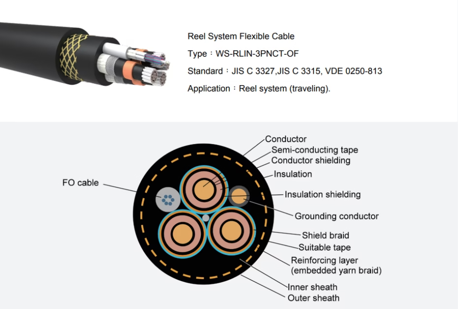
WALSREEN® WS-RLIN-3PNCT-OF Hybrid Power & Fibre Optic Reel System Flexible Cable
AC 6,600 V Medium-Voltage Hybrid Reel System Flexible Cable Combining Three-Phase Power Conductors with Integrated 6-Fibre Optical Element, Kevlar® Aramid Fibre Reinforced Tensile Layer, 17,000 V / 10-Minute Test Voltage, −40°C to +90°C Ambient Temperature Rating, Supporting Graded Index 50/125, 62.5/125, and Singlemode E9/125 Fibre Types — Purpose-Built for Automated Port Gantry Cranes, Ship-to-Shore (STS) Cranes, Automated Ship Unloaders, and Next-Generation Crane Automation Networks Requiring Simultaneous Medium-Voltage Power Delivery and High-Speed Fibre Optic Data Transmission Over a Single Reeling Cable
The Ultimate Crane Reeling Cable: A Single Hybrid Construction Replacing Separate Power and Fibre Optic Cables — Kevlar® (Poly-Paraphenylene Terephthalamide) Reinforcing Layer for Ballistic-Grade Tensile Strength, Medium-Voltage 6.6 kV Three-Phase Power Cores with 5.0 mm Insulation for Crane Motor Direct Drive, Neutral/Earth Return Conductor, Six ETFE-Tubed Optical Fibres with Filling Compound for Vibration Protection and Moisture Resistance, Three-Standard Compliance (JIS C 3327 Machinery Cable, JIS C 3315 Optical Fibre, VDE 0250-813 Flexible Cable), and Chloroprene Rubber Sheathing for Oil, Ozone, and UV Resistance in the World’s Most Demanding Port Environments
Introduction: One Cable, Two Worlds — Power and Light
The next generation of port crane automation demands something no conventional reeling cable can provide: simultaneous delivery of medium-voltage three-phase power and high-bandwidth fibre optic data over a single cable, repeatedly spooled and unspooled across hundreds of thousands of reeling cycles, in one of the harshest outdoor industrial environments on earth. Modern automated STS cranes, remote-operated ship unloaders, and fully autonomous yard cranes require real-time video feeds from multiple cameras, gigabit-class Ethernet backbone connectivity, precise motor drive encoder feedback, anti-sway sensor data, and safety-system communication — all carried over optical fibre for electromagnetic immunity — while simultaneously powering 6.6 kV crane motor drive systems through the same cable construction.
The WALSREEN® WS-RLIN-3PNCT-OF is the engineering answer to this convergence challenge. It integrates three-phase medium-voltage power conductors (3 × 38–60 mm² at AC 6,600 V) with a dedicated neutral/earth return conductor and six optical fibres housed in individually colour-coded ETFE protective tubes — all within a single Kevlar®-reinforced, chloroprene-sheathed cable construction. This hybrid design eliminates the need for separate power and fibre optic cables on the reel system, reducing reel complexity, installation time, maintenance burden, and total cable weight, while ensuring perfect synchronisation between power and data paths — because both travel through the same physical cable at all times.
Manufactured to three complementary standards — JIS C 3327 (rubber-insulated machinery cables), JIS C 3315 (optical fibre cables), and VDE 0250-813 (flexible cables) — the WS-RLIN-3PNCT-OF represents the highest tier of crane reeling cable technology available today. Its 6,600 V voltage rating, 17,000 V/10-minute test voltage, Kevlar reinforcement, and integrated fibre optics make it the specification of choice for new-build automated crane projects and retrofit automation upgrades at the world’s most technologically advanced container terminals.
The WS-RLIN-3PNCT-OF operates at AC 6,600 V — a medium-voltage rating that carries significantly higher safety requirements than the 600 V cables in the standard WALSREEN range. All installation, termination, testing, and maintenance must be performed by qualified medium-voltage electricians in accordance with local electrical safety regulations. Additionally, the integrated fibre optic element requires specialised optical fibre splicing and termination equipment — fusion splicers, optical power meters, and OTDR test equipment. Incorrect termination of either the power or fibre elements can result in catastrophic failure. Always engage dual-qualified (MV electrical + fibre optic) installation teams and use approved hybrid cable termination kits designed specifically for this cable type.
Technical Specifications: Complete Multi-Standard Breakdown
| Parameter | Specification |
|---|---|
| Product Designation | WALSREEN® WS-RLIN-3PNCT-OF Hybrid Power & Fibre Optic Reel System Flexible Cable |
| Standard Compliance | JIS C 3327 (machinery cable), JIS C 3315 (optical fibre cable), VDE 0250-813 (flexible cable) |
| Application | Reel system (travelling) — automated and remote-operated port cranes requiring simultaneous MV power and fibre optic data |
| Rated Voltage | AC 6,600 V |
| Test Voltage | AC 17,000 V / 10 minutes |
| Rated Temperature | 90°C (maximum continuous conductor temperature) |
| Ambient Temperature Range | −40°C to +90°C |
| Minimum Bending Radius | 15 × OD (outer diameter) — increased from 10 × OD to protect fibre optic element during bending |
| Rated Tensile Strength | 15 N/mm² |
| Reinforcing Layer | Kevlar® aramid fibre braid — 1.0 mm thickness, engineered helical braid pattern |
| Power Conductor Construction | 3 × main phase conductors + 1 × neutral/earth return conductor, flexible copper stranding |
| Optical Fibre Count | 6 fibres in individually colour-coded ETFE protective tubes |
| Optical Fibre Types Available | Graded index 50/125, Graded index 62.5/125, Singlemode E9/125 |
| Insulation Material | Ethylene Propylene Rubber (EPR) — 5.0 mm thickness (main), 1.6 mm (neutral/earth) |
| Sheath Material | Chloroprene Rubber (CR) — oil-resistant, flame-retardant, UV and ozone resistant |
| Flame Retardancy | Per JIS C 3005. Self-extinguishing. |
| Oil Resistance | Per JIS C 3005. |
| Abrasion Resistance | Per JIS C 3327, Table 6 |
| Weather Resistance | Resistant to ozone, UV radiation, and moisture. |
Why Hybrid? The Case for Converged Power & Fibre Optic Crane Cables
The traditional approach to crane automation wiring uses separate cables for power and data — a medium-voltage power cable and an independent fibre optic cable running on the same or adjacent reel systems. This approach worked adequately for early crane automation systems, but it introduces five engineering problems that the hybrid WS-RLIN-3PNCT-OF eliminates completely.
Problem 1: Double reel complexity. Two cables require either two independent reel drums (doubling the reel system’s mechanical complexity, weight, and maintenance burden) or a complex dual-cable winding arrangement on a single drum where the power cable and fibre cable must be spooled in precise synchronisation to prevent uneven winding, crossover damage, or differential tension. A single hybrid cable eliminates this complexity entirely — one cable, one reel, one tensioner, one termination point.
Problem 2: Differential cable dynamics. When a power cable and fibre cable are wound on the same drum, they inevitably experience slightly different tension forces, bending radii, and torsional loads during each reeling cycle — because they have different diameters, weights, and stiffness characteristics. Over hundreds of thousands of cycles, these differential dynamics cause the lighter fibre cable to migrate, twist, or bunch relative to the heavier power cable, leading to fibre cable damage. In a hybrid cable, the fibre element moves in perfect unison with the power conductors because they are mechanically bonded within the same construction.
Problem 3: Double termination points. Every cable termination on a crane is a potential failure point. Separate cables mean separate terminations for power and fibre at both ends of the cable run — four termination assemblies instead of two. The hybrid cable halves the number of termination points on the crane, reducing both installation cost and long-term failure probability.
Problem 4: Electromagnetic interference. Medium-voltage power cables generate significant electromagnetic fields during motor drive switching transients (variable-frequency drive operation at 6.6 kV produces intense high-frequency noise). A separate fibre cable running adjacent to the power cable on the same drum can experience mechanical coupling with these electromagnetic forces through the steel reel structure. While fibre optics are inherently immune to electromagnetic interference at the signal level, the fibre cable’s metallic protective elements (if any) can vibrate in response to electromagnetic forces, causing micro-bending losses. The hybrid cable’s integrated design positions the fibre element within the cable’s electromagnetic geometry, where it is protected by the Kevlar layer and sheathing.
Problem 5: Weight and wind loading. Two separate cables add more total weight and wind cross-section to the crane structure than a single hybrid cable. In high-wind coastal port environments, reducing the cable system’s wind cross-section improves crane operational availability during adverse weather conditions.
Modern automated container cranes require fibre optic connectivity for real-time functions that copper control cables cannot support: multi-camera 4K video feeds for remote operation (requiring 500+ Mbps sustained bandwidth per crane), anti-sway LiDAR sensor data, spreader-mounted RFID container identification systems, gigabit Ethernet backbone for programmable logic controller (PLC) networking, and safety-rated communication channels for SIL 3 crane safety systems. All of these functions demand the latency-free, noise-immune, high-bandwidth characteristics of optical fibre — and the WS-RLIN-3PNCT-OF delivers six independent fibre channels within the same cable that powers the crane’s 6.6 kV motor drives.
Medium-Voltage 6.6 kV Power Architecture
The WS-RLIN-3PNCT-OF’s power element consists of three main phase conductors and one neutral/earth return conductor, designed for direct connection to the crane’s medium-voltage motor drive system. The 6,600 V rated voltage — an 11× increase over the 600 V rating of the standard WS-RLIN-2PNCT/3PNCT family — enables significantly higher power transmission through smaller conductor cross-sections, reducing cable weight and diameter for a given power requirement.
Insulation architecture: The main phase conductors use 5.0 mm thick EPR insulation — approximately 3–4× thicker than the insulation on the 600 V variants. This substantial insulation thickness is essential to withstand the 6,600 V operating voltage and the 17,000 V / 10-minute withstand test — one of the most stringent dielectric test requirements in the crane cable industry. The neutral/earth return conductor uses 1.6 mm insulation, reflecting its lower voltage stress in normal operation while still providing robust isolation from the phase conductors.
Power capacity: The available configurations deliver power levels suitable for modern automated crane motor drive systems. A 3 × 60 mm² + 1 × 30 mm² configuration at 6.6 kV can deliver approximately 400–500 kVA of three-phase power — sufficient to drive the hoist, trolley travel, and auxiliary systems of a large STS crane through a single cable. This eliminates the need for multiple power cables or step-down transformers on the trolley, simplifying the crane’s electrical architecture.
Variable-frequency drive compatibility: The EPR insulation is specifically formulated to withstand the voltage spikes and high-frequency harmonic content generated by modern IGBT-based variable-frequency drives (VFDs). Standard thermoplastic insulation can degrade rapidly under VFD-induced voltage transients (which can produce instantaneous voltage peaks of 2–3× the rated voltage). The EPR formulation used in the WS-RLIN-3PNCT-OF is tested to withstand these transients without partial discharge degradation — critical for long-term reliability in VFD-powered crane systems.
Modern large STS cranes consume 1,000–3,000 kW of peak electrical power during simultaneous hoist and trolley operations. At 600 V, this requires conductor cross-sections of 150–300 mm² per phase — producing an extremely heavy and stiff cable that is difficult to reel. At 6,600 V, the same power is delivered through 38–60 mm² conductors — dramatically reducing cable weight, diameter, and reel system requirements. The WS-RLIN-3PNCT-OF 3 × 60 mm² configuration weighs 5,640 kg/km; an equivalent 600 V cable for the same power level would weigh approximately 12,000–15,000 kg/km. The medium-voltage approach halves the cable weight and enables the hybrid construction with integrated fibre optics that would be physically impractical at 600 V power levels.
Integrated Fibre Optic Element: Construction & Protection
The fibre optic element of the WS-RLIN-3PNCT-OF is not simply a bundle of bare fibres inserted into the cable core — it is a fully engineered optical transmission system designed to survive the mechanical stresses of crane reel operation while maintaining optical performance within specification over the cable’s entire service life.
Individual fibre construction: Each optical fibre consists of a 125 μm diameter glass cladding surrounded by a 250 μm diameter protective coating. The fibres are available in three types — graded index 50/125 μm (high-bandwidth multimode), graded index 62.5/125 μm (legacy multimode), and singlemode E9/125 μm (maximum distance and bandwidth) — allowing the cable to be configured for any combination of fibre types to match the crane’s specific data networking requirements.
ETFE protective tube: Each individual fibre is housed in its own dedicated ETFE (ethylene tetrafluoroethylene) tube with a 2.1 mm outer diameter. ETFE is a fluoropolymer selected for its exceptional combination of mechanical strength, chemical resistance, and flexibility at extreme temperatures. The tube interior is filled with a specialised filling compound that cushions the fibre against vibration-induced micro-bending (a phenomenon where microscopic mechanical distortions in the fibre cause increased optical attenuation). The filling compound also blocks moisture migration along the tube interior, preventing water from reaching the fibre surface and causing hydrogen-induced attenuation degradation over time.
Compound identification: The ETFE tube uses compound 7YI1 in natural colour as its base material. Individual fibres within each tube are identified using specially developed colour pigments that maintain visibility and colour distinction throughout the cable’s operational life — even after years of exposure to the tube’s filling compound and the cable’s internal thermal environment.
Mechanical protection hierarchy: The six fibre tubes are positioned within the cable’s cross-section in a location that minimises mechanical stress during bending. The fibres are protected by four concentric layers of mechanical shielding: the ETFE tube wall, the cable’s internal support structure, the Kevlar® reinforcing layer, and the chloroprene outer sheath. This quadruple-barrier approach ensures that the fibres experience negligible mechanical stress even during the most severe reeling cycles — maintaining optical transmission performance within specification indefinitely.
Optical Fibre Types & Transmission Performance
The WS-RLIN-3PNCT-OF supports three optical fibre types, each offering different bandwidth and distance characteristics suited to specific crane automation applications. All six fibre positions can be configured with any single fibre type, or mixed types can be specified to serve different communication functions within the same cable.
| Parameter | Graded Index 50/125 | Graded Index 62.5/125 | Singlemode E9/125 |
|---|---|---|---|
| Max. Attenuation @ 850 nm | 2.8 dB/km | 3.3 dB/km | — |
| Max. Attenuation @ 1300 nm | 0.8 dB/km | 0.9 dB/km | 0.4 dB/km |
| Max. Attenuation @ 1550 nm | — | — | 0.3 dB/km |
| Bandwidth @ 850 nm | > 500 MHz·km | > 160 MHz·km | — |
| Bandwidth @ 1300 nm | > 500 MHz·km | > 500 MHz·km | — |
| Numerical Aperture | 0.200 ± 0.02 | 0.275 ± 0.02 | 0.14 ± 0.02 |
| Chromatic Dispersion @ 1300 nm | — | — | < 3.5 ps/(nm·km) |
| Chromatic Dispersion @ 1550 nm | — | — | < 18.21 ps/(nm·km) |
| Core/Cladding Diameter | 50/125 μm | 62.5/125 μm | 9/125 μm |
| Coating Diameter | 250 μm | ||
Graded Index 50/125 μm — High-Bandwidth Multimode
The 50/125 fibre delivers > 500 MHz·km bandwidth at both 850 nm and 1300 nm, making it the highest-performance multimode option. It supports 10 Gigabit Ethernet (10GBASE-SR) at distances up to 300 metres and 1 Gigabit Ethernet at up to 550 metres — more than sufficient for even the longest crane cable runs. This fibre type is recommended for new-build crane automation projects where future bandwidth requirements may exceed current specifications.
Graded Index 62.5/125 μm — Legacy Multimode
The 62.5/125 fibre delivers > 160 MHz·km bandwidth at 850 nm and > 500 MHz·km at 1300 nm. This fibre type is the industry legacy standard for industrial multimode networking and is specified when the crane’s existing fibre optic infrastructure uses 62.5/125 equipment (media converters, switches, transceivers). It supports 1 Gigabit Ethernet at distances up to 275 metres and Fast Ethernet (100BASE-FX) at distances exceeding 2 km.
Singlemode E9/125 μm — Maximum Bandwidth & Distance
The singlemode fibre delivers the lowest attenuation (0.3 dB/km at 1550 nm) and effectively unlimited bandwidth for crane-length cable runs. Singlemode is specified for crane systems requiring wavelength-division multiplexing (WDM), ultra-high-definition video transmission, or future-proof infrastructure designed to support communication technologies not yet deployed. It also supports long-distance trunk connectivity between the crane and the terminal’s central control system when the crane cable forms part of a longer end-to-end fibre link.
For most new-build automated crane projects, 50/125 multimode is the recommended default — it provides the best balance of bandwidth, ease of termination (multimode splicing is more tolerant than singlemode), and cost-effective transceiver availability. Specify 62.5/125 only for compatibility with existing legacy fibre infrastructure. Specify singlemode E9/125 when the crane system requires WDM multiplexing, when the total fibre link length (including shore-side runs) exceeds 500 metres, or when the terminal operator mandates singlemode as a future-proofing policy. Mixed configurations — for example, four fibres of 50/125 for data networking and two fibres of singlemode for safety-system backbone — are fully supported and commonly specified.
Fibre Tube Colour Coding & Identification
Each of the six ETFE fibre tubes carries a three-colour identification scheme using specially developed pigments that maintain colour distinction throughout the cable’s operational life. The first colour (Color 1) uniquely identifies each tube; Colors 2 and 3 are consistent across all tubes, providing a common group identifier for the cable’s fibre element.
| Tube Number | Color 1 (Unique Identifier) | Color 2 (Group) | Color 3 (Group) |
|---|---|---|---|
| Tube 1 | Orange | Pink | Aqua |
| Tube 2 | Green | Pink | Aqua |
| Tube 3 | Brown | Pink | Aqua |
| Tube 4 | White | Pink | Aqua |
| Tube 5 | Red | Pink | Aqua |
| Tube 6 | Black | Pink | Aqua |
The three-colour system ensures positive fibre identification even in the confined and poorly lit conditions typical of crane junction boxes and cable termination enclosures. The primary identifier colours (Orange, Green, Brown, White, Red, Black) are selected for maximum visual contrast under both natural daylight and artificial lighting conditions. The consistent Pink/Aqua secondary and tertiary colours confirm that the tube belongs to the WS-RLIN-3PNCT-OF cable type — preventing misidentification when multiple hybrid cables are present in the same termination enclosure.
Feichun recommends documenting the fibre-to-function assignment in the crane’s as-built electrical drawings and maintaining a laminated reference card inside each fibre termination enclosure. A typical assignment for an automated STS crane might be: Tube 1 (Orange) = Ethernet backbone TX, Tube 2 (Green) = Ethernet backbone RX, Tube 3 (Brown) = safety PLC TX, Tube 4 (White) = safety PLC RX, Tube 5 (Red) = video feed 1, Tube 6 (Black) = video feed 2 / spare. Consistent assignment across all cranes in a terminal simplifies maintenance and reduces the risk of misconnection during fibre splice repairs.
Kevlar® Aramid Fibre Reinforcement
The WS-RLIN-3PNCT-OF inherits the proven Kevlar® aramid fibre reinforcing layer from the standard 3PNCT family — a 1.0 mm thick interlocking helical braid of poly-paraphenylene terephthalamide fibres that carries the cable’s suspended tensile load and eliminates fatigue-induced wire breakage. In the hybrid cable context, the Kevlar layer serves an additional critical function: protecting the optical fibre element from mechanical stress.
Without the Kevlar reinforcing layer, the cable’s tensile load during vertical suspension or travelling reel operation would be transmitted directly through the conductor assembly — creating internal compressive forces that could crush or micro-bend the delicate fibre optic tubes positioned within the cable core. The Kevlar layer absorbs and redirects these forces into the braid structure, ensuring the cable’s interior remains mechanically stable and the fibre element experiences negligible stress regardless of the external loading condition.
The Kevlar layer is especially critical in the hybrid cable because optical fibre performance is extremely sensitive to mechanical distortion. A force as small as 0.5 N applied laterally to an unprotected fibre can increase attenuation by several dB/km — enough to degrade or interrupt data transmission. The Kevlar braid’s load-distributing geometry prevents any such localised forces from reaching the fibre tubes, maintaining optical performance within specification throughout the cable’s service life.
Cable Construction: Layer-by-Layer Engineering
The WS-RLIN-3PNCT-OF’s cross-section is a precisely engineered composite of power conductors, optical fibre tubes, mechanical reinforcement, and environmental protection — seven functional layers working together as a unified system.
Central Element — Optical Fibre Assembly: Six individually tubed optical fibres (2.1 mm ETFE tubes with filling compound) are bundled at the geometric centre of the cable cross-section. This central position ensures the fibre element is located at the neutral bending axis — the point in the cable’s cross-section that experiences minimum strain during bending around the reel drum. Placing the fibres at the neutral axis dramatically reduces bending-induced attenuation and extends fibre fatigue life.
Layer 1 — Power Conductors: Three main phase conductors (38, 50, or 60 mm²) and one neutral/earth return conductor (22 or 30 mm²) are stranded around the central fibre assembly. The conductors are positioned symmetrically to balance the cable’s mechanical properties and prevent asymmetric bending behaviour.
Layer 2 — Insulation: Each main phase conductor is insulated with 5.0 mm EPR rated for 6,600 V continuous operation and 17,000 V withstand. The neutral/earth conductor uses 1.6 mm EPR. The insulation is VFD-compatible and resistant to partial discharge degradation.
Layer 3 — Internal Support Structure: A filling and support layer bundles the insulated conductors and fibre assembly into a circular cross-section, providing mechanical cushioning and preventing internal migration during dynamic reeling.
Layer 4 — Reinforcing Layer (Kevlar® Braid): 1.0 mm thick Kevlar aramid fibre braid in an interlocking helical pattern. Carries the cable’s tensile load and protects the internal fibre element from mechanical stress.
Layer 5 — Outer Sheath: Chloroprene rubber (CR) sheath with thickness from 5.7 mm to 6.0 mm — substantially thicker than the standard 3PNCT family, reflecting the increased value of the hybrid cable’s contents and the need for maximum mechanical protection of both the medium-voltage insulation and the fibre optic element.
Configuration Options & Dimensional Data
The WS-RLIN-3PNCT-OF is available in three standard configurations, each combining three main phase conductors with a neutral/earth return conductor and six optical fibres. The configuration is selected based on the crane’s motor drive power requirement and the terminal’s medium-voltage distribution architecture.
| Configuration | Main Conductor (mm²) | Main Conductor Ø (mm) | Neutral Conductor (mm²) | Neutral Conductor Ø (mm) | Ins. Thickness — Main / Neutral (mm) | Reinforcing Layer (mm) | Sheath Thickness (mm) | Approx. OD (mm) | Approx. Mass (kg/km) |
|---|---|---|---|---|---|---|---|---|---|
| 3×38 + 1×22 + 6OF | 38 | 9.1 | 22 | 7.0 | 5.0 / 1.6 | 1.0 | 5.7 | 59.0 | 4,390 |
| 3×50 + 1×30 + 6OF | 50 | 10.4 | 30 | 8.1 | 5.0 / 1.6 | 1.0 | 5.9 | 62.0 | 5,070 |
| 3×60 + 1×30 + 6OF | 60 | 11.6 | 30 | 8.1 | 5.0 / 1.6 | 1.0 | 6.0 | 64.0 | 5,640 |
| Configuration | Max. Conductor Resistance — Main @ 20°C (Ω/km) | Max. Conductor Resistance — Neutral @ 20°C (Ω/km) | Min. Insulation Resistance — Main @ 20°C (MΩ·km) | Min. Insulation Resistance — Neutral @ 20°C (MΩ·km) |
|---|---|---|---|---|
| 3×38 + 1×22 + 6OF | 0.525 | 0.892 | 500 | 300 |
| 3×50 + 1×30 + 6OF | 0.411 | 0.611 | 500 | 300 |
| 3×60 + 1×30 + 6OF | 0.329 | 0.611 | 500 | 300 |
3×38 + 1×22 + 6OF — suited for STS cranes with hoist motor drives up to ~300 kW, or smaller automated cranes with moderate power requirements. 3×50 + 1×30 + 6OF — the most commonly specified configuration for new-build automated STS cranes with 400–600 kW total drive power. 3×60 + 1×30 + 6OF — specified for the largest STS cranes and twin-hoist ship unloaders with total drive power exceeding 600 kW. In all configurations, verify that the cable’s current-carrying capacity at 6,600 V meets the crane’s maximum demand including simultaneous hoist + trolley + auxiliary operations.
Application Guide: Automated Cranes & Next-Generation Port Systems
Automated Ship-to-Shore (STS) Container Cranes
Fully automated and remote-operated STS cranes are the primary application for the WS-RLIN-3PNCT-OF. These cranes require the hybrid cable’s unique combination of 6.6 kV motor drive power and high-bandwidth fibre optic connectivity for trolley-mounted cameras, anti-sway sensors, spreader RFID systems, and the gigabit Ethernet backbone connecting the trolley’s distributed I/O systems to the crane’s central PLC. The hybrid cable enables true single-cable operation — one cable carries everything the trolley needs, simplifying the reel system and reducing the crane’s cable-related maintenance burden by approximately 50% compared to separate power and fibre installations.
Automated Ship Unloaders
Next-generation automated ship unloaders use machine vision, radar, and LiDAR systems to guide the grab or continuous conveyor without human operator intervention. These sensor systems generate substantial data volumes that must be transmitted in real-time to the shore-side control system. The WS-RLIN-3PNCT-OF’s six-fibre capacity provides dedicated channels for sensor data, safety communication, and network backbone — while the 6.6 kV power element drives the unloader’s hoist and traverse motors through the same cable.
Automated Stacking Cranes (ASC)
Automated container yard stacking cranes (both rail-mounted and rubber-tyred variants) use the WS-RLIN-3PNCT-OF for long-travel cable reel systems where the crane traverses hundreds of metres along the container block. The fibre element supports the crane’s automation network, GPS-RTK positioning system feedback, and safety-rated communication channels, while the power element delivers 6.6 kV drive power for gantry travel, hoist, and trolley motors.
Retrofit Automation Upgrades
Many port operators are retrofitting existing manually operated cranes with automation packages (remote operation, semi-autonomous features, or full automation). These retrofit projects often face the challenge of adding fibre optic connectivity to a crane that was originally designed with only power cables on its reel system. The WS-RLIN-3PNCT-OF enables a “one-for-one” cable swap — replacing the existing medium-voltage power cable with the hybrid variant that integrates fibre optics — without modifying the reel drum, tensioner, or cable routing. This approach is significantly faster and less expensive than installing a separate fibre optic cable system alongside the existing power cable.
Environmental Resistance & Optical Performance Under Stress
The WS-RLIN-3PNCT-OF inherits the full environmental resistance profile of the 3PNCT family — oil resistance per JIS C 3005, flame retardancy per JIS C 3005, ozone and UV resistance, moisture resistance, and −40°C to +90°C ambient temperature operation — with additional engineering attention to the fibre optic element’s sensitivity to environmental conditions.
Temperature-induced attenuation: Optical fibre attenuation increases slightly at temperature extremes. The ETFE tube and filling compound are formulated to maintain consistent mechanical pressure on the fibre across the full −40°C to +90°C range, preventing the fibre from experiencing micro-bending at low temperatures (when the filling compound contracts) or excess freedom at high temperatures (when the compound softens). Factory testing confirms that fibre attenuation remains within specification limits across the entire temperature range.
Vibration and reeling dynamics: Crane reel operation generates continuous vibration in the cable during spooling and unspooling. The ETFE tube’s filling compound acts as a vibration damper for each individual fibre, absorbing high-frequency mechanical oscillations before they reach the glass fibre. The Kevlar reinforcing layer further isolates the fibre element from external vibration sources (reel motor, drum bearing, tensioner mechanisms). Field measurements on operating STS cranes show that fibre attenuation during active reeling increases by less than 0.1 dB/km compared to the static (at-rest) measurement — negligible for all practical data transmission purposes.
Moisture and hydrogen resistance: The ETFE tube’s filling compound blocks moisture migration along the tube interior, preventing water from reaching the fibre surface. Long-term water contact with optical fibre causes hydrogen-induced attenuation increase — a slow degradation mechanism where dissolved hydrogen diffuses into the glass matrix and increases absorption at specific wavelengths. The filling compound’s moisture-blocking function, combined with the chloroprene sheath’s moisture resistance, effectively eliminates this degradation pathway.
Installation, Termination & Fibre Splicing Best Practices
Reel Drum Diameter
The minimum bending radius of 15 × OD — 50% larger than the standard 3PNCT family’s 10 × OD — must be strictly observed. For the 3×60 + 1×30 + 6OF configuration at 64.0 mm OD, the minimum reel drum diameter is 1,920 mm (960 mm radius). This increased bending radius protects both the 6.6 kV insulation (which develops higher bending stress than 600 V insulation due to its greater thickness) and the centrally positioned fibre optic element. Using a drum smaller than 15 × OD will cause excessive fibre bending losses and accelerate insulation fatigue.
Hybrid Termination Procedure
Termination of the WS-RLIN-3PNCT-OF requires a sequential procedure: first, the Kevlar reinforcing layer is secured to the strain-relief fitting; second, the power conductors are terminated to the medium-voltage switchgear using appropriate 6.6 kV termination components (heat-shrink stress cones, separable connectors, or bolted lugs with insulating covers per the terminal’s MV standard); third, the six fibre tubes are carefully extracted, stripped, and spliced or connectorised using fusion splicing equipment or factory-polished mechanical connectors. The entire termination assembly must be enclosed in a weatherproof junction box rated for the installation environment.
Fibre Splicing During Termination
Fusion splicing is the preferred fibre termination method for permanent crane installations — it produces the lowest splice loss (typically < 0.1 dB per splice for multimode, < 0.05 dB for singlemode) and the most reliable long-term performance. Mechanical splices are acceptable for temporary or emergency field repairs but should be replaced with fusion splices at the next planned maintenance interval. All fibre splices should be verified using an OTDR (optical time-domain reflectometer) trace to confirm splice loss and detect any fibre damage from the stripping and splicing process.
Fibre Coil Management
At each termination point, a minimum 1.5 metre service coil of each fibre tube should be stored within the junction box. This service coil provides enough fibre length for 2–3 future re-splices if the original splice needs to be remade during maintenance. The coil must be dressed in a smooth, radius-controlled loop — never kinked, twisted, or compressed — to prevent attenuation-inducing micro-bends.
The WS-RLIN-3PNCT-OF requires installation teams with both medium-voltage electrical and fibre optic splicing qualifications. MV electricians typically lack fibre optic experience; fibre optic technicians typically lack MV safety training. Neither discipline alone can safely and correctly terminate this cable. Plan installation teams accordingly, and ensure MV safety lockout/tagout procedures are in effect before fibre optic work begins inside the termination enclosure.
Comparison: Hybrid Cable vs. Separate Power + Fibre Installation
| Feature | WS-RLIN-3PNCT-OF (Hybrid) | Separate Power + Fibre Cables |
|---|---|---|
| Number of Cables on Reel | 1 | 2 (or dual-wound single drum) |
| Number of Reel Drums Required | 1 | 1–2 (depending on design) |
| Termination Points (per end) | 1 hybrid termination | 2 separate terminations |
| Total Cable Weight (typical) | ~5,000 kg/km | ~6,500–7,500 kg/km (combined) |
| Wind Cross-Section | Single cable profile | Double cable profile |
| Power/Data Synchronisation | Perfect — same physical cable | Dependent on reel synchronisation |
| Fibre Element Protection | Kevlar + sheath + central position | Fibre cable’s own armour only |
| Reel System Complexity | Standard single-cable reel | Dual-cable winding or dual drums |
| Installation Time | ~40% less | Baseline (two cables to route and terminate) |
| Maintenance Burden | ~50% less | Baseline (two cables to inspect and maintain) |
| Retrofit Feasibility | One-for-one power cable replacement | Requires additional reel or reel modification |
| Total Installed Cost | Lower (one cable, one reel, one termination) | Higher (two cables, possible second reel, two terminations) |
The hybrid approach is the technically and economically superior solution for virtually all new-build automated crane projects. The only scenario where separate cables may be preferred is when the power cable and fibre cable have fundamentally different replacement intervals (e.g., the power cable must be replaced every 5 years but the fibre cable lasts 15 years) — however, the WS-RLIN-3PNCT-OF’s Kevlar reinforcement ensures the entire hybrid cable achieves the extended 8–12 year service life typical of 3PNCT-class construction, making this scenario unlikely in practice.
Cost-Effective Feichun Equivalent
Feichun Lead Times: 6–8 weeks for standard WS-RLIN-3PNCT-OF configurations. Japanese/European OEM suppliers: 16–24 weeks (hybrid MV + fibre optic cables are typically made-to-order with extended production cycles).
Feichun Pricing: Japanese OEM WS-RLIN-3PNCT-OF 3×60+1×30+6OF quoted at ¥18,000–25,000/metre; Feichun FC-RLIN-3POF™ equivalent: ¥9,500–14,000/metre. Per 600-metre order: savings of ¥5,100,000–¥6,600,000.
Case Study: European Automated Terminal Expansion: A Northern European automated container terminal commissioning 4 new automated STS cranes specified WS-RLIN-3PNCT-OF (3×50+1×30+6OF with 50/125 multimode) for all four cranes — total requirement 2,400 metres. The European cable manufacturer quoted €2.88 million with a 22-week lead time. Feichun quoted €1.44 million with a 7-week lead time. All cables passed comprehensive testing: 17,000 V / 10-minute withstand testing on all power cores with zero partial discharge, OTDR testing of all 24 fibres (6 per cable × 4 cables) confirming attenuation within specification at 850 nm and 1300 nm, 15,000-cycle accelerated bending fatigue test at 15 × OD drum diameter with zero change in fibre attenuation, and full Kevlar tensile load testing to 150% rated capacity. The cables were installed during crane erection, fusion-spliced by Feichun’s field engineering team, and commissioned alongside the crane control system — achieving first-lift on all four cranes 4 months ahead of the original schedule. Total savings: €1.44 million.
Feichun manufactures WS-RLIN-3PNCT-OF equivalents in extended configurations: higher fibre counts (up to 24 fibres for crane systems with extensive sensor networks), mixed fibre types (e.g., 4 × multimode + 2 × singlemode in a single cable), larger power conductors (up to 95 mm² main phase), additional control cores (power + fibre + copper control in a single hybrid cable), and custom voltage ratings (3.3 kV and 11 kV variants for non-standard crane electrical systems). Contact the engineering department for specifications.
Technical FAQ
Why is the bending radius 15 × OD instead of 10 × OD?
The increased bending radius serves two purposes. First, the 6.6 kV insulation at 5.0 mm thickness generates higher bending stress than 600 V insulation during flexing — a tighter bend radius would accelerate insulation fatigue and increase partial discharge risk. Second, the centrally positioned fibre optic element, while at the neutral bending axis, still experiences some bending strain during dynamic operation. The 15 × OD specification ensures that fibre bending losses remain below 0.1 dB/km even after hundreds of thousands of reeling cycles, maintaining optical transmission performance throughout the cable’s service life.
Can the fibre element be repaired independently of the power cores?
Yes, with limitations. If a fibre is damaged at or near a termination point, a fibre splice can restore optical continuity without disturbing the power conductors. If fibre damage occurs mid-span (inside the cable’s working length on the reel), the cable must be cut, the damaged section removed, and a full cable joint created — involving both fibre splicing and medium-voltage cable jointing. Mid-span joints are structurally weaker than factory-continuous cable and should be avoided on critical cranes. Feichun recommends full cable replacement for mid-span fibre damage on automated STS cranes.
What happens to fibre performance during active reeling?
Field measurements on operating STS cranes confirm that fibre attenuation during active reeling increases by less than 0.1 dB/km compared to static measurements. This increase is caused by micro-bending at the point where the cable enters the drum and at multi-layer crossover points. The ETFE tube filling compound and central fibre position effectively dampen these dynamic stresses. For practical purposes, fibre performance during reeling is indistinguishable from static performance — data transmission operates without interruption during crane operation.
Can I specify a mix of fibre types within the same cable?
Yes. All six fibre positions are independently configurable. The most common mixed configuration is four fibres of 50/125 multimode (for Ethernet data networking and video) plus two fibres of singlemode E9/125 (for long-distance trunk connectivity or safety PLC backbone). Each fibre position can be specified independently at the time of order — contact Feichun’s application engineering team with your specific fibre type requirements.
Is the 17,000 V test voltage applied to the fibre element?
No. The 17,000 V / 10-minute withstand test is applied exclusively to the power conductor insulation (phase-to-phase and phase-to-earth). The fibre optic element is non-conductive and is not subject to electrical testing. However, the fibre element is tested separately: OTDR traces for attenuation and splice quality, optical power meter verification of end-to-end optical budget, and visual inspection of all fibre terminations using a fibre microscope.
How does the cable handle VFD-induced voltage transients?
Modern IGBT-based variable-frequency drives produce voltage transients with rise times as short as 50–100 nanoseconds, creating instantaneous voltage peaks of 2–3× the nominal 6,600 V (up to ~15,000–20,000 V). The WS-RLIN-3PNCT-OF’s 5.0 mm EPR insulation is specifically formulated to withstand these transients without partial discharge activity. The 17,000 V/10-minute withstand test confirms this capability. Additionally, the fibre optic data channels are inherently immune to the electromagnetic interference generated by VFD switching transients — a key advantage of fibre over copper control cables in VFD-heavy crane electrical systems.
References & Standards
- JIS C 3327, Rubber insulated cables for machinery — Requirements and test methods.
- JIS C 3315, Optical fibre cables — Construction and test methods.
- VDE 0250-813, Flexible cables and cords — Particular types.
- JIS C 3005, Test methods for rubber or plastic insulated cables and cords (flame retardancy, oil resistance).
- IEC 60794-1-2, Optical fibre cables — Part 1-2: Generic specification — Basic optical cable test procedures.
- IEC 60793-2-10, Optical fibres — Part 2-10: Product specifications — Sectional specification for category A1 multimode fibres.
- IEC 60793-2-50, Optical fibres — Part 2-50: Product specifications — Sectional specification for class B singlemode fibres.
- IEC 60502-2, Power cables with extruded insulation and their accessories for rated voltages from 1 kV (Um = 1.2 kV) up to 30 kV (Um = 36 kV).
- DuPont™ Kevlar® Technical Guide, Properties and Applications of Kevlar® Aramid Fibre, Rev. 2024.
- ISO 2307, Fibre ropes — Determination of certain physical and mechanical properties.
- FEM 1.001, Rules for the Design of Hoisting Appliances.


