
AC 600 V Reel System Flexible Cables in Standard (2PNCT) and Kevlar® Aramid Fibre Reinforced (3PNCT) Variants, Steel-Wire-Stranded Conductors for Enhanced Tension Resistance, −40°C to +90°C Ambient Temperature Rating, 3 to 30 Cores with Conductor Sizes from 3.5 mm² to 60 mm² — Purpose-Built for Travelling Cable Reel Systems in Port Gantry Cranes, Ship-to-Shore (STS) Cranes, Ship Unloaders, Grab Cranes, and Heavy-Duty Industrial Machinery
Comprehensive Crane Reeling Cable Family: Two Distinct Performance Tiers — WS-RLIN-2PNCT Standard Construction for Cost-Effective Reeling Applications, and WS-RLIN-3PNCT with Kevlar® (Poly-Paraphenylene Terephthalamide) Aramid Fibre Reinforcing Layer — The Same Ballistic Body Armour Material — Braided in a Proprietary Helical Pattern for Exceptional Tensile Strength Without Sacrificing Flexibility, Both Featuring Steel-Stranded Conductors (≤8 mm²), Chloroprene Rubber Sheathing for Oil, Ozone, and UV Resistance, Full JIS C 3327 Compliance, and Proven Reliability in the World’s Busiest Container Terminals and Bulk-Handling Ports
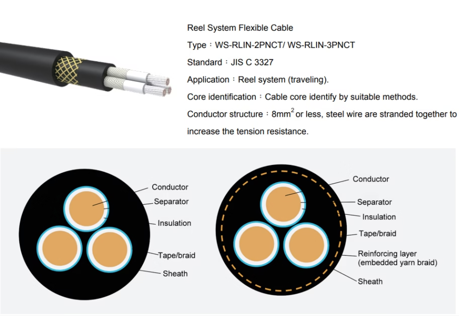
WALSREEN® WS-RLIN-2PNCT / WS-RLIN-3PNCT Reel System Flexible Cable
AC 600 V Reel System Flexible Cables in Standard (2PNCT) and Kevlar® Aramid Fibre Reinforced (3PNCT) Variants, Steel-Wire-Stranded Conductors for Enhanced Tension Resistance, −40°C to +90°C Ambient Temperature Rating, 3 to 30 Cores with Conductor Sizes from 3.5 mm² to 60 mm² — Purpose-Built for Travelling Cable Reel Systems in Port Gantry Cranes, Ship-to-Shore (STS) Cranes, Ship Unloaders, Grab Cranes, and Heavy-Duty Industrial Machinery
Comprehensive Crane Reeling Cable Family: Two Distinct Performance Tiers — WS-RLIN-2PNCT Standard Construction for Cost-Effective Reeling Applications, and WS-RLIN-3PNCT with Kevlar® (Poly-Paraphenylene Terephthalamide) Aramid Fibre Reinforcing Layer — The Same Ballistic Body Armour Material — Braided in a Proprietary Helical Pattern for Exceptional Tensile Strength Without Sacrificing Flexibility, Both Featuring Steel-Stranded Conductors (≤8 mm²), Chloroprene Rubber Sheathing for Oil, Ozone, and UV Resistance, Full JIS C 3327 Compliance, and Proven Reliability in the World’s Busiest Container Terminals and Bulk-Handling Ports
Introduction: Two Cables, One Mission — Reliable Crane Reeling
Modern port logistics infrastructure demands electrical cables that can withstand punishing mechanical conditions no ordinary flexible cable is designed to endure. A travelling cable reel system on a ship-to-shore container crane, bulk ship unloader, or harbour gantry crane repeatedly spools and unspools the cable as the trolley, grab, or spreader traverses its operating range — subjecting the cable to continuous tensile loading, cyclical bending around the reel drum, torsional forces from crane slew motion, and environmental assault from coastal salt spray, UV radiation, hydraulic oil contamination, and extreme temperature swings. The cable must survive hundreds of thousands of these combined loading cycles across a service life measured in years, not months.
The WALSREEN® product family addresses this challenge with two distinct performance tiers, both manufactured to JIS C 3327 — the Japanese Industrial Standard for rubber-insulated machinery cables — and both engineered specifically for travelling reel system applications.
WS-RLIN-2PNCT (Standard Construction) provides a robust, cost-effective reeling cable with steel-stranded conductors, chloroprene rubber sheathing, and full environmental resistance for applications where moderate cycle counts or budget constraints make a premium reinforcement unnecessary. This cable is the workhorse of the family — reliable, proven, and economical for the majority of crane reeling installations worldwide.
WS-RLIN-3PNCT (Kevlar® Reinforced Construction) adds a Kevlar® aramid fibre reinforcing layer — the same poly-paraphenylene terephthalamide material used in military ballistic body armour — braided in a proprietary helical pattern between the conductor assembly and outer sheath. This reinforcement transforms the cable’s tensile and fatigue performance, delivering 2–3× the cycle life of the standard variant and enabling reliable operation in the most demanding high-cycle, high-tension crane applications on earth.
Both variants share the same conductor range (3 to 30 cores, 3.5 mm² to 60 mm²), the same electrical ratings (AC 600 V, 90°C), and the same environmental specifications (oil-resistant, flame-retardant, ozone/UV/moisture resistant). The choice between 2PNCT and 3PNCT is determined by the mechanical demands of the specific installation — cycle count, suspended cable weight, reel drum diameter, and required service life.
The WS-RLIN-2PNCT and WS-RLIN-3PNCT are not interchangeable without engineering review. The 3PNCT variant has a larger overall diameter and greater mass per unit length than the equivalent 2PNCT configuration (due to the added Kevlar reinforcing layer and thicker insulation). Upgrading from 2PNCT to 3PNCT on an existing reel system may require verification of reel drum capacity, tensioner settings, cable entry gland dimensions, and total cable weight within the reel motor’s torque range. Always consult the reel system manufacturer or Feichun’s application engineering team before substituting one variant for the other.
Technical Specifications: Complete JIS C 3327 Breakdown
| Parameter | WS-RLIN-2PNCT (Standard) | WS-RLIN-3PNCT (Kevlar® Reinforced) |
|---|---|---|
| Standard Compliance | JIS C 3327 (Rubber-insulated cables for machinery) | |
| Application | Reel system (travelling) — horizontal and inclined cable reel systems on port cranes, ship unloaders, and industrial machinery | |
| Rated Voltage | AC 600 V | |
| Test Voltage | AC 3,000 V / 1 minute | |
| Rated Temperature | 90°C (maximum continuous conductor temperature) | |
| Ambient Temperature Range | −40°C to +90°C | |
| Minimum Bending Radius | 10 × OD (outer diameter) | |
| Rated Tensile Strength | 15 N/mm² | |
| Conductor Structure | Steel wire stranded — for conductors ≤8 mm², steel wires are stranded together with copper to increase tension resistance | |
| Reinforcing Layer | None | Kevlar® aramid fibre braid — embedded yarn braid using poly-paraphenylene terephthalamide fibres in an engineered helical pattern |
| Insulation Material | Ethylene Propylene Rubber (EPR) — high-temperature, high-flexibility elastomer | |
| Sheath Material | Chloroprene Rubber (CR) — oil-resistant, flame-retardant, UV and ozone resistant | |
| Flame Retardancy | Per JIS C 3005. Self-extinguishing. | |
| Oil Resistance | Per JIS C 3005. Resistant to hydraulic oil, lubricants, and diesel fuel contact. | |
| Abrasion Resistance | Per JIS C 3327, Table 6 | |
| Weather Resistance | Resistant to ozone, UV radiation, and moisture. Suitable for permanent outdoor installation. | |
| Core Identification | Cable cores identified by suitable methods per JIS standard. | |
| Core Range | 3 to 30 cores (including 3, 4, 6, 10, 12, 16, 20, 24, 30-core configurations) | |
| Conductor Size Range | 3.5 mm² to 60 mm² | |
2PNCT vs. 3PNCT: Choosing the Right Tier
The fundamental decision between the WS-RLIN-2PNCT and WS-RLIN-3PNCT centres on a single engineering question: does the application’s mechanical duty cycle justify the additional cost and diameter of Kevlar reinforcement? The answer depends on four interrelated factors — expected cycle count over the cable’s planned service interval, suspended cable weight (a function of cable length and core count), reel drum diameter relative to the cable’s bending radius, and the cost of unplanned crane downtime for cable replacement.
Choose WS-RLIN-2PNCT (Standard) when the reel system operates at moderate cycle counts (under 100,000 cycles per year), the suspended cable length is short (under 30 metres), the reel drum diameter comfortably exceeds the minimum bending radius, or the crane is not on a critical-path production line where unplanned downtime carries severe financial consequences. Typical applications include rail-mounted gantry cranes in container storage yards, level-luffing harbour cranes, waste-processing installations, and industrial overhead cranes with motorised cable reels.
Choose WS-RLIN-3PNCT (Kevlar® Reinforced) when the application demands maximum reliability and cycle life — STS container cranes operating 20+ hours per day at 30+ lifts per hour, bulk ship unloaders with heavy grab cycles, any installation where the suspended cable length exceeds 50 metres, or mission-critical cranes where unplanned downtime costs US$50,000+ per day in lost throughput. The Kevlar reinforcement typically extends cable service life from 3–5 years (standard) to 8–12 years (reinforced) in high-cycle STS crane applications, eliminating 1–2 complete cable replacements over the crane’s operational life.
A useful rule of thumb: if the total cost of one unplanned cable replacement (cable material + crane downtime + labour + vessel waiting charges) exceeds three times the price premium of the 3PNCT over the 2PNCT variant, the Kevlar-reinforced cable is the economically rational choice regardless of current budget constraints. In busy container terminals where vessel waiting charges alone can exceed US$25,000 per day, this threshold is almost always met for STS cranes and ship unloaders.
Kevlar® Aramid Fibre Reinforcement: Ballistic-Grade Tensile Strength
The WS-RLIN-3PNCT’s defining engineering innovation is its Kevlar® aramid fibre reinforcing layer. Kevlar — chemically known as poly-paraphenylene terephthalamide — is the same synthetic fibre used to manufacture military ballistic body armour, helicopter rotor blades, racing yacht sails, and Formula 1 chassis components. Its selection for crane reeling cable reinforcement is driven by a unique combination of material properties that no other reinforcement fibre can match in the context of travelling reel system operation.
Tensile strength five times greater than steel by weight. Kevlar fibre delivers a tensile strength of approximately 3,620 MPa — compared to 400–550 MPa for high-carbon steel wire typically used in conventional cable armour. When measured on a strength-to-weight ratio basis, Kevlar is roughly five times stronger than steel. This means a Kevlar-reinforced cable can carry the same suspended load as a steel-braided cable while being significantly lighter — a critical advantage in travelling reel systems where the cable’s own weight is a primary design constraint for the reel motor and tensioner.
Zero fatigue-induced wire breakage. Conventional steel-braided reeling cables suffer from a well-documented failure mode: individual steel armour wires break after repeated bending cycles around the reel drum, creating sharp wire ends that pierce the insulation and cause short circuits. Kevlar fibres do not exhibit this brittle-fracture behaviour. The aramid fibre’s molecular structure distributes bending stress uniformly along the fibre length, preventing the stress-concentration cracking that causes steel wire fatigue failure. This eliminates the single most common cause of reeling cable failure in port crane applications.
Chemical and thermal stability. Kevlar does not rust, corrode, or degrade when exposed to saltwater, hydraulic oil, diesel fuel, or the chloroprene rubber compounds used in the cable’s sheath. It maintains full tensile strength from −40°C to well above the cable’s rated 90°C operating temperature. Unlike steel reinforcement, which corrodes and loses structural integrity when moisture penetrates the sheath through micro-cracks, Kevlar reinforcement is inherently immune to corrosion — a critical durability advantage in salt-spray-laden port environments.
The engineering parallel between bulletproof vests and crane cables is genuine, not merely commercial. A ballistic vest must absorb the kinetic energy of a high-velocity projectile and distribute it across a wide area without tearing, breaking, or permanently deforming. A crane reeling cable must absorb the gravitational and dynamic loads of travelling reel operation and distribute them across the cable’s cross-section without stretching, breaking, or permanently deforming. Both applications demand extreme tensile strength, energy absorption without brittle failure, and long-term structural integrity under repeated loading. Kevlar excels at all three — which is precisely why it was selected for both applications.
The Engineered Braid Pattern: How the Reinforcing Layer Works
Simply wrapping Kevlar fibres around a cable core would provide minimal tensile reinforcement. The critical engineering lies in the braiding geometry — the specific pattern in which individual Kevlar yarn bundles are interwoven around the cable’s insulated conductor assembly. The WS-RLIN-3PNCT uses a proprietary helical braid pattern that transforms individual yarn strands into a unified load-bearing structure.
In this construction, multiple Kevlar yarn carriers are braided simultaneously around the cable core, with each yarn bundle following a helical path at a precisely controlled braid angle. Half the carriers travel in a clockwise helix; the other half travel counter-clockwise. Where the two sets of carriers cross, they interlock — creating a woven tubular structure that behaves mechanically like a single continuous shell rather than a collection of individual fibres. This interlocking geometry ensures that tensile load applied along the cable’s axis is distributed uniformly across all Kevlar yarns simultaneously, preventing any single yarn from carrying a disproportionate share of the load.
The braid angle is carefully calibrated to optimise the trade-off between tensile strength and bending flexibility. A low braid angle (fibres nearly parallel to the cable axis) maximises axial tensile strength but reduces bending flexibility. A high braid angle (fibres nearly perpendicular to the axis) maximises flexibility but reduces tensile performance. The WS-RLIN-3PNCT’s braid angle is engineered to deliver 15 N/mm² rated tensile strength while maintaining a 10 × OD minimum bending radius — the ideal balance for travelling reel systems where the cable must bend around the reel drum while supporting its own weight during transit across the crane structure.
Some competing cables claim “aramid reinforcement” but use simple parallel-laid or spirally wound yarns rather than a true interlocking braid. Parallel-laid yarns can slip relative to each other under load, concentrating stress on individual strands. A spirally wound yarn can unwind under torsion — a significant risk in travelling reel systems where the cable experiences rotational forces during crane slew operations. The WS-RLIN-3PNCT’s interlocking helical braid eliminates both failure modes — the yarns physically cannot slip or unwind because they are woven through each other.
Steel-Stranded Conductor Construction: Mechanical Durability Under Load
Both the WS-RLIN-2PNCT and WS-RLIN-3PNCT incorporate steel wires stranded together with copper conductors in all configurations with conductor sizes of 8 mm² or less. This hybrid conductor construction addresses the fundamental mechanical challenge of reel system operation: even with external reinforcement (in the 3PNCT) or robust sheathing (in the 2PNCT), the conductor cores themselves must resist the compressive and tensile forces generated during repeated spooling and unspooling cycles.
The steel wires are stranded concentrically with the copper conductors in a pattern that positions the steel elements at the core of each conductor bundle. This placement ensures the steel carries the majority of the axial tensile load within the conductor assembly, while the surrounding copper strands carry electrical current unimpeded. The steel stranding also prevents copper conductors from necking (reducing in cross-section under tension) or cold-flowing (permanent deformation under sustained mechanical load) — failure modes that would increase electrical resistance and reduce current-carrying capacity over the cable’s service life.
For conductor sizes larger than 8 mm² (14, 22, 30, 38, and 60 mm² in the available range), the copper cross-section itself provides sufficient mechanical strength, and the conductor construction transitions to standard flexible stranding. This size-dependent approach optimises material cost — steel reinforcement is applied only where the conductor’s natural cross-section cannot withstand the mechanical loads of reel system operation.
A 3.5 mm² copper conductor has a cross-sectional area small enough that the tensile force from a 40-metre suspended cable can exceed the copper’s yield strength, causing permanent elongation and resistance increase. By stranding steel wires into the conductor core, the effective tensile capacity increases by approximately 3–4×, ensuring the copper strands remain within their elastic deformation range throughout the cable’s operational life. Larger conductors (14 mm²+) have enough copper cross-section to resist these forces without supplemental steel reinforcement.
Cable Construction: Layer-by-Layer Engineering
WS-RLIN-2PNCT (Standard Construction — 3 Layers)
Layer 1 — Conductor: Steel-stranded copper conductors (≤8 mm²) or standard flexible copper conductors (>8 mm²). Conductor diameters range from 2.6 mm (3.5 mm²) to 11.6 mm (60 mm²). Optimised for flexibility during bending around the reel drum while maintaining consistent electrical performance.
Layer 2 — Insulation: High-temperature elastomer insulation with thickness ranging from 0.8 mm (small conductor multi-core configurations) to 1.5 mm (3 × 60 mm²). Rated for 90°C continuous operation. Provides reliable electrical isolation at 600 V with a 3,000 V/1-minute test voltage safety margin.
Layer 3 — Sheath: Chloroprene rubber (CR) outer sheath with thickness from 2.2 mm to 3.4 mm. Flame retardant per JIS C 3005, oil-resistant per JIS C 3005, and resistant to ozone, UV radiation, and moisture for permanent outdoor installation.
WS-RLIN-3PNCT (Kevlar® Reinforced Construction — 4 Layers)
Layer 1 — Conductor: Identical to 2PNCT. Steel-stranded copper conductors (≤8 mm²) or standard flexible copper conductors (>8 mm²).
Layer 2 — Insulation: Higher-specification elastomer insulation with increased thickness ranging from 1.2 mm (multi-core configurations) to 2.1 mm (3 × 60 mm²). The thicker insulation in the 3PNCT provides additional dielectric margin and mechanical cushioning against the Kevlar reinforcing layer.
Layer 3 — Reinforcing Layer (Kevlar® Embedded Yarn Braid): The defining feature of the 3PNCT. Multiple Kevlar aramid fibre yarn bundles braided in an interlocking helical pattern around the insulated conductor assembly. This layer carries the cable’s tensile load and provides resistance to torsion, impact, and abrasion. Reinforcing layer thickness ranges from 0.5 mm (small-conductor configurations) to 1.0 mm (larger configurations).
Layer 4 — Sheath: Chloroprene rubber (CR) outer sheath with increased thickness from 3.1 mm to 4.5 mm — approximately 40–50% thicker than the equivalent 2PNCT sheath, providing additional mechanical protection for the Kevlar reinforcing layer and enhanced abrasion resistance against the reel drum surface.
Configuration Options — WS-RLIN-2PNCT (Standard)
The WS-RLIN-2PNCT is available in fifteen standard configurations across two conductor families: power-grade configurations (3 and 4 cores, 8–60 mm²) for crane motor circuits, and multi-core control configurations (6–30 cores, 3.5–8 mm²) for crane control, signal, and auxiliary circuits.
Power-Grade Configurations (3 & 4 Cores, 8–60 mm²)
| No. of Cores | Conductor Size (mm²) | Conductor Ø (mm) | Insulation Thickness (mm) | Sheath Thickness (mm) | Approx. OD (mm) | Approx. Mass (kg/km) | Max. Cond. Res. 20°C (Ω/km) | Min. Ins. Res. 20°C (MΩ·km) |
|---|---|---|---|---|---|---|---|---|
| 3 | 8 | 3.8 | 1.0 | 2.2 | 18.0 | 515 | 2.52 | 400 |
| 3 | 14 | 4.9 | 1.0 | 2.3 | 21.0 | 650 | 1.43 | 300 |
| 3 | 22 | 7.0 | 1.2 | 2.7 | 26.0 | 1,030 | 0.919 | 300 |
| 3 | 30 | 8.1 | 1.2 | 2.8 | 29.0 | 1,300 | 0.681 | 300 |
| 3 | 38 | 9.1 | 1.2 | 3.0 | 31.0 | 1,580 | 0.541 | 200 |
| 3 | 60 | 11.6 | 1.5 | 3.4 | 39.0 | 2,440 | 0.339 | 200 |
| 4 | 38 | 9.1 | 1.2 | 3.1 | 34.0 | 2,070 | 0.541 | 200 |
Multi-Core Control Configurations (6–30 Cores, 3.5–8 mm²)
| No. of Cores | Conductor Size (mm²) | Conductor Ø (mm) | Insulation Thickness (mm) | Sheath Thickness (mm) | Approx. OD (mm) | Approx. Mass (kg/km) | Max. Cond. Res. 20°C (Ω/km) | Min. Ins. Res. 20°C (MΩ·km) |
|---|---|---|---|---|---|---|---|---|
| 6 | 3.5 | 2.6 | 0.8 | 2.2 | 18.0 | 505 | 5.54 | 400 |
| 6 | 8 | 3.8 | 1.0 | 2.5 | 24.0 | 950 | 2.52 | 400 |
| 10 | 3.5 | 2.6 | 0.8 | 2.6 | 24.0 | 820 | 5.54 | 400 |
| 12 | 3.5 | 2.6 | 0.8 | 2.6 | 25.0 | 925 | 5.54 | 400 |
| 16 | 3.5 | 2.6 | 0.8 | 2.6 | 28.0 | 1,200 | 5.54 | 400 |
| 20 | 3.5 | 2.6 | 0.8 | 2.6 | 31.0 | 1,480 | 5.54 | 400 |
| 24 | 3.5 | 2.6 | 0.8 | 2.6 | 34.0 | 1,780 | 5.54 | 400 |
| 30 | 3.5 | 2.6 | 0.8 | 2.6 | 37.0 | 2,130 | 5.54 | 400 |
Configuration Options — WS-RLIN-3PNCT (Kevlar® Reinforced)
The WS-RLIN-3PNCT mirrors the 2PNCT’s configuration range with the addition of the Kevlar® aramid fibre reinforcing layer. Note the increased insulation thickness, the dedicated reinforcing layer, increased sheath thickness, and consequently larger overall diameters and higher mass values compared to the equivalent 2PNCT configurations.
Power-Grade Configurations (3 & 4 Cores, 8–60 mm²)
| No. of Cores | Conductor Size (mm²) | Conductor Ø (mm) | Ins. Thickness (mm) | Reinforcing Layer (mm) | Sheath Thickness (mm) | Approx. OD (mm) | Approx. Mass (kg/km) | Max. Cond. Res. 20°C (Ω/km) | Min. Ins. Res. 20°C (MΩ·km) |
|---|---|---|---|---|---|---|---|---|---|
| 3 | 8 | 3.8 | 1.2 | 0.5 | 3.1 | 22.0 | 665 | 2.52 | 400 |
| 3 | 14 | 4.9 | 1.2 | 1.0 | 3.3 | 26.0 | 940 | 1.43 | 400 |
| 3 | 22 | 7.0 | 1.6 | 1.0 | 3.7 | 32.0 | 1,490 | 0.919 | 300 |
| 3 | 30 | 8.1 | 1.6 | 1.0 | 3.9 | 35.0 | 1,830 | 0.681 | 300 |
| 3 | 38 | 9.1 | 1.6 | 1.0 | 4.0 | 37.0 | 2,170 | 0.541 | 300 |
| 3 | 60 | 11.6 | 2.1 | 1.0 | 4.5 | 45.0 | 3,360 | 0.339 | 300 |
| 4 | 38 | 9.1 | 1.6 | 1.0 | 4.2 | 40.0 | 2,720 | 0.541 | 300 |
Multi-Core Control Configurations (6–30 Cores, 3.5–8 mm²)
| No. of Cores | Conductor Size (mm²) | Conductor Ø (mm) | Ins. Thickness (mm) | Reinforcing Layer (mm) | Sheath Thickness (mm) | Approx. OD (mm) | Approx. Mass (kg/km) | Max. Cond. Res. 20°C (Ω/km) | Min. Ins. Res. 20°C (MΩ·km) |
|---|---|---|---|---|---|---|---|---|---|
| 6 | 3.5 | 2.6 | 1.2 | 0.5 | 3.2 | 24.0 | 730 | 5.54 | 500 |
| 6 | 8 | 3.8 | 1.2 | 0.5 | 3.5 | 28.0 | 1,180 | 2.52 | 400 |
| 10 | 3.5 | 2.6 | 1.2 | 1.0 | 3.7 | 38.0 | 1,190 | 5.54 | 500 |
| 12 | 3.5 | 2.6 | 1.2 | 1.0 | 3.7 | 33.0 | 1,320 | 5.54 | 500 |
| 16 | 3.5 | 2.6 | 1.2 | 1.0 | 3.9 | 36.0 | 1,650 | 5.54 | 500 |
| 20 | 3.5 | 2.6 | 1.2 | 1.0 | 4.1 | 40.0 | 2,000 | 5.54 | 500 |
| 24 | 3.5 | 2.6 | 1.2 | 1.0 | 4.4 | 44.0 | 2,400 | 5.54 | 500 |
| 30 | 3.5 | 2.6 | 1.2 | 1.0 | 4.5 | 46.0 | 2,830 | 5.54 | 500 |
The 3PNCT multi-core control configurations deliver a minimum insulation resistance of 500 MΩ·km — a 25% improvement over the 2PNCT’s 400 MΩ·km specification. This results from the thicker insulation (1.2 mm vs. 0.8 mm) in the 3PNCT variant. For crane control circuits carrying sensitive encoder signals, limit switch inputs, or communication bus data, this higher insulation resistance provides a measurably cleaner signal environment and improved noise immunity.
Application Guide: Port Cranes, Ship Unloaders & Travelling Reel Systems
Ship-to-Shore (STS) Container Gantry Cranes
STS gantry cranes represent the most demanding application for travelling reel system cables. The cable connects the crane’s fixed electrical infrastructure to the moving trolley/spreader assembly via a motorised cable reel mounted on the boom or trolley. During each container lift cycle, the cable spools and unspools as the trolley traverses the boom — a typical cycle of 200–400 metres of cable travel. A high-throughput STS crane performs 25–40 container lifts per hour, 18–22 hours per day, 350+ days per year, subjecting the cable to over 300,000 bending and tensioning cycles annually. For these cranes, the WS-RLIN-3PNCT (Kevlar reinforced) is strongly recommended; the WS-RLIN-2PNCT may be acceptable for lower-throughput terminal operations.
Ship Unloaders & Grab Cranes
Bulk material ship unloaders (for coal, iron ore, grain, cement, and other commodities) use grab buckets or continuous vertical conveyors that demand reliable cable reel systems. The cable must withstand not only standard tensile and bending loads but also shock loads generated when a loaded grab bucket is arrested during hoisting. The WS-RLIN-3PNCT’s Kevlar reinforcement absorbs these shock loads elastically — the aramid fibres stretch slightly under peak load and return to their original length without permanent deformation.
Rail-Mounted & Rubber-Tyred Gantry Cranes (RMG/RTG)
Container yard gantry cranes use horizontal travelling cable reel systems for power and signal distribution. These applications typically generate lower tensile loads than STS crane boom-trolley systems, making the WS-RLIN-2PNCT an excellent cost-effective choice. The WS-RLIN-3PNCT is recommended for RTG cranes with long cable travel distances (>300 metres) or in terminals requiring extended maintenance intervals.
Level-Luffing Harbour Cranes & Mobile Harbour Cranes
Harbour cranes serving general cargo, project cargo, and breakbulk operations use cable reel systems for power supply during rail travel or quay traversal. The WS-RLIN-2PNCT’s multi-core control configurations (10–30 cores at 3.5 mm²) are well-suited for complex crane automation control circuits, while the power-grade configurations (3 × 22 mm² to 3 × 60 mm²) serve the crane’s main hoist, luff, and slew motor circuits.
Industrial & Landfill Applications
Beyond port environments, both cable variants are specified for travelling reel systems in steel mill ladle cranes, waste-to-energy facility cranes, landfill compactors, mining draglines, and other heavy industrial machinery sharing the same fundamental requirement — a cable that maintains electrical and mechanical integrity across hundreds of thousands of reeling cycles in harsh environments.
Environmental Resistance: Oil, Ozone, UV & Extreme Temperatures
Port crane cables operate in one of the harshest electrical cable environments on earth. The combination of coastal salt spray, direct UV radiation, wide temperature swings, airborne industrial contaminants, and contact with hydraulic fluids demands comprehensive environmental resistance from every layer of the cable construction.
Oil resistance (JIS C 3005): The chloroprene rubber sheath on both variants resists swelling, softening, and degradation when exposed to hydraulic oil, lubricating grease, diesel fuel, and other petroleum-based fluids. Crane reeling cables routinely route through or near hydraulic systems where oil leaks and splashes are unavoidable.
Ozone and UV resistance: Both variants are formulated to resist ozone cracking — a degradation mechanism where atmospheric ozone attacks the polymer chains in rubber materials, causing surface cracking that propagates into structural failure. Coastal and tropical port environments have elevated ozone concentrations due to intense solar radiation.
Temperature performance (−40°C to +90°C): The extended ambient temperature range covers arctic port installations at the low end and Middle Eastern and tropical port environments at the high end. The 90°C conductor temperature rating provides substantial headroom above the ambient maximum.
Moisture resistance: The chloroprene sheath provides excellent resistance to moisture ingress from rain, humidity, and salt spray. In the 3PNCT variant, the Kevlar reinforcing layer provides an additional barrier — and unlike steel reinforcement, Kevlar is inherently hydrophobic and does not lose tensile strength when wet.
Installation & Reel System Best Practices
Reel Drum Diameter
The minimum bending radius of 10 × OD must be respected in reel drum design for both variants. For the largest standard configuration — 3PNCT 30-core 3.5 mm² at 46.0 mm OD — the minimum reel drum diameter is 920 mm. Most modern port crane reel systems use drum diameters of 800–1,200 mm, comfortably exceeding the minimum for most configurations.
Cable Tensioner Calibration
Motorised cable reel systems use spring-loaded or servo-controlled tensioners to maintain consistent cable tension. The tensioner must be calibrated to prevent loose wraps (which cause cable-on-cable abrasion) without exceeding the cable’s rated tensile capacity. Both variants share a rated tensile strength of 15 N/mm², but the 3PNCT’s Kevlar reinforcement provides significantly higher ultimate breaking strength, offering greater safety margin for shock loads.
Termination & Strain Relief
For the 2PNCT, cone-type strain-relief fittings that grip the outer sheath are appropriate. For the 3PNCT, the termination must specifically engage the Kevlar reinforcing layer — not just the outer sheath. Wedge-type or compression-ring fittings designed for braided-reinforced cables are recommended. Terminations that grip only conductor cores bypass the reinforcement and must never be used.
Multi-Layer Spooling
When wound in multiple layers, inner layers experience compressive loading from outer layers. The 3PNCT’s Kevlar layer distributes this force uniformly and prevents cable flattening. The 2PNCT, lacking this layer, is more susceptible to deformation — making proper level-winding even more critical to prevent localised pressure concentrations at crossover points.
Comparison: 2PNCT Standard vs. 3PNCT Kevlar® Reinforced
| Feature | WS-RLIN-2PNCT (Standard) | WS-RLIN-3PNCT (Kevlar®) |
|---|---|---|
| Reinforcement | None | Kevlar® aramid fibre braid (1.0 mm) |
| Insulation Thickness | 1.2 mm | 1.6 mm (+33%) |
| Sheath Thickness | 3.0 mm | 4.0 mm (+33%) |
| Overall Diameter | 31.0 mm | 37.0 mm (+19%) |
| Mass | 1,580 kg/km | 2,170 kg/km (+37%) |
| Min. Insulation Resistance | 200 MΩ·km | 300 MΩ·km (+50%) |
| Fatigue Wire Breakage Risk | Moderate (sheath wear over time) | None — Kevlar does not fracture |
| Corrosion Resistance | Sheath-dependent | Sheath + Kevlar (corrosion-immune reinforcement) |
| Shock Load Absorption | Limited to sheath elasticity | Excellent — Kevlar absorbs and returns |
| Expected Service Life (STS crane) | 3–5 years | 8–12 years |
| Expected Cycle Life | 100,000–200,000 cycles | 500,000+ cycles |
| Relative Cable Cost | 100% | ~130–150% |
| Total Cost of Ownership | Higher (more replacements) | Lower (fewer replacements, less downtime) |
Choose WS-RLIN-2PNCT for moderate-duty applications — yard cranes, harbour cranes, industrial overhead cranes, and installations with planned replacement intervals under 5 years. Choose WS-RLIN-3PNCT for high-duty applications — STS container cranes, ship unloaders, and any installation where maximum cycle life, minimum downtime, and lowest total cost of ownership are the primary objectives.
Cost-Effective Feichun Equivalent
Feichun Lead Times: 4–6 weeks for standard 2PNCT and 3PNCT configurations. Japanese OEM suppliers: 12–18 weeks.
Feichun Pricing (3PNCT Kevlar® Reinforced): Japanese OEM WS-RLIN-3PNCT 3 × 38 mm² quoted at ¥9,000–13,000/metre; Feichun FC-RLIN-3P™ equivalent: ¥4,500–7,000/metre. Per 800-metre order: savings of ¥3,600,000–¥4,800,000.
Feichun Pricing (2PNCT Standard): Japanese OEM WS-RLIN-2PNCT 3 × 38 mm² quoted at ¥6,500–9,500/metre; Feichun FC-RLIN-2P™ equivalent: ¥3,200–5,000/metre.
Case Study: Middle Eastern Container Terminal Expansion: A major Middle Eastern container terminal expanding its quayside with 8 new STS cranes and 24 RTG cranes needed a comprehensive cable reel solution. The specification called for WS-RLIN-3PNCT (Kevlar reinforced) for all STS cranes (3 × 38 mm² power + 20-core 3.5 mm² control per crane = 6,400 metres total) and WS-RLIN-2PNCT (standard) for the RTG cranes (16-core 3.5 mm² control = 9,600 metres total). The Japanese OEM quoted US$2.4 million with a 20-week lead time. Feichun quoted US$1.15 million with a 6-week lead time — delivered in two phased shipments aligned with crane erection. All cables passed comprehensive testing: 3PNCT tensile load testing to 150% rated capacity with zero Kevlar yarn breakage, 50,000-cycle accelerated bending fatigue test, oil immersion per JIS C 3005, and full electrical testing per JIS C 3327. Total savings: US$1.25 million with 14 weeks faster delivery.
Feichun manufactures both 2PNCT and 3PNCT equivalents in extended configurations: higher core counts (up to 61 cores for complex crane automation), larger conductor sizes (up to 95 mm² for high-power motor circuits), hybrid power + fibre optic for integrated crane networking, composite cables combining power, control, and signal cores in a single 3PNCT construction, screened/shielded variants for EMC-sensitive systems, and custom Kevlar braid densities for ultra-high-cycle applications. Contact the engineering department for specifications.
Technical FAQ
When should I upgrade from 2PNCT to 3PNCT?
Upgrade to 3PNCT when: the reel system exceeds 100,000 cycles per year, the suspended cable length exceeds 50 metres, crane downtime costs more than US$10,000 per day, the environment is severely corrosive (coastal, chemical, or offshore), or maintenance intervals must exceed 5 years. For STS cranes and ship unloaders in busy terminals, 3PNCT is almost always the more economical choice over a 10-year horizon.
Why does the conductor structure change at 8 mm²?
Conductors of 8 mm² and below have a copper cross-section too small to independently withstand reeling tensile forces. Steel wire stranding increases tensile capacity by 3–4× without significantly affecting conductivity. Conductors above 8 mm² have sufficient copper cross-section to resist these forces mechanically, making steel reinforcement unnecessary.
Can I use 2PNCT power cable with 3PNCT control cable on the same crane?
Yes — this is a common and cost-effective approach. The power cable may operate at moderate cycles, making 2PNCT adequate. The control cable benefits from the 3PNCT’s higher insulation resistance (500 MΩ·km) for signal integrity and Kevlar reinforcement for fatigue life. Feichun supports mixed-variant installations with matched termination hardware kits.
What is the maximum continuous cable length available?
Feichun manufactures both variants in continuous lengths up to 1,000 metres on standard reels. For runs exceeding 1,000 metres (mining draglines, long RTG travel paths), continuous lengths up to 2,000 metres can be produced on oversized reels. Joints or splices should be avoided — a continuous length is always preferred.
Does the 3PNCT’s Kevlar layer affect electromagnetic properties?
No. Kevlar is completely non-conductive and electromagnetically transparent. Unlike steel armour (which can act as an unintended shield or antenna), Kevlar has zero effect on electrical properties, signal integrity, or EMC. This is advantageous for multi-core cables carrying sensitive signals alongside power conductors.
What temperature does Kevlar reinforcement withstand?
Kevlar maintains full tensile strength up to ~250°C and decomposes at ~500°C — it does not melt. The cable’s −40°C to +90°C rating is limited by rubber materials, not Kevlar. During thermal excursions (fire, welding), Kevlar maintains structural integrity well after rubber materials have degraded, providing a critical safety buffer.
References & Standards
- JIS C 3327, Rubber insulated cables for machinery — Requirements and test methods.
- JIS C 3005, Test methods for rubber or plastic insulated cables and cords (flame retardancy testing).
- JIS C 3005, Test methods for rubber or plastic insulated cables and cords (oil resistance testing).
- IEC 60228, Conductors of insulated cables — Classes and construction.
- DuPont™ Kevlar® Technical Guide, Properties and Applications of Kevlar® Aramid Fibre, Rev. 2024.
- IEC 60332-1-2, Vertical flame propagation test on single insulated wires or cables.
- ISO 2307, Fibre ropes — Determination of certain physical and mechanical properties.
- ASTM D885, Standard Test Methods for Tire Cords, Tire Cord Fabrics, and Industrial Filament Yarns Made from Manufactured Organic-Base Fibers.
- FEM 1.001, Rules for the Design of Hoisting Appliances — Classification and Loading on Structures and Mechanisms.
- ISO 12944, Paints and varnishes — Corrosion protection of steel structures — port environment corrosivity classification (C5-M marine atmosphere).


