
Comprehensive Technical Analysis of Next-Generation Medium Voltage Trailing Cables with Enhanced Bare Copper Conductors and PROTOLON Insulation for Opencast Mining Operations
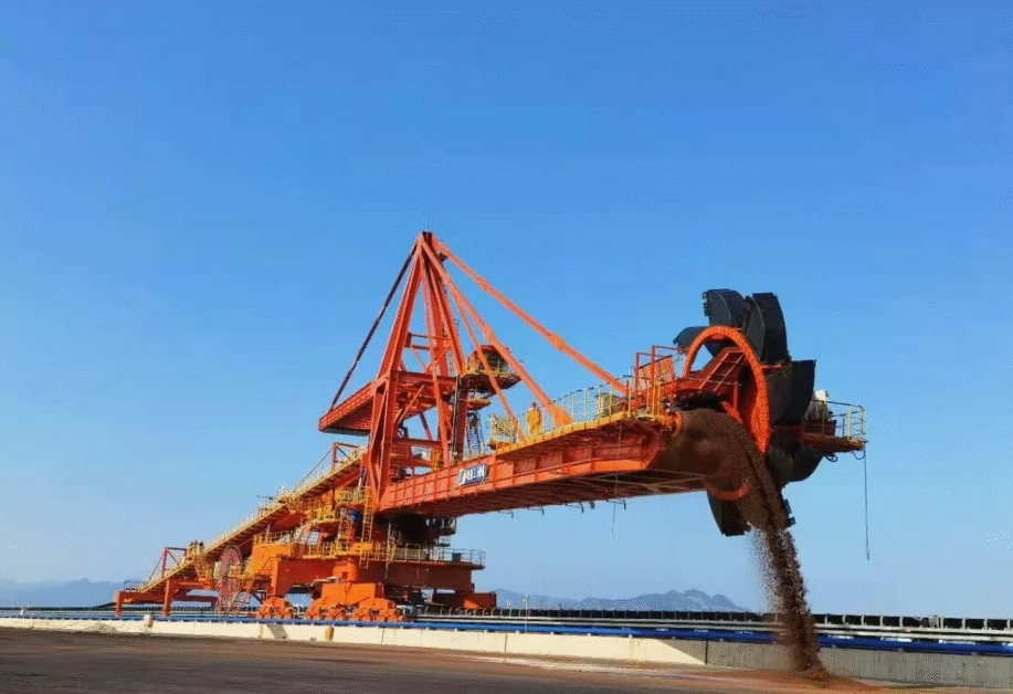
PROTOLON(SB-SAM) (N)TSCGEWOEU 6 kV – 20 kV: Advanced Mining Cable Technology for Extreme Conditions
Comprehensive Technical Analysis of Next-Generation Medium Voltage Trailing Cables with Enhanced Bare Copper Conductors and PROTOLON Insulation for Opencast Mining Operations
Manufacturer: Anhui Feichun Special Cable Co., Ltd. (安徽飞纯特种电缆有限公司)
Technical Support: [email protected] | [email protected] | [email protected]
1. Executive Summary and Cable Purpose
The PROTOLON(SB-SAM) (N)TSCGEWOEU represents the latest evolution in medium voltage trailing cable technology, specifically engineered for power supply and connection applications in large material handling machines operating in opencast mining environments. This advanced cable system incorporates bare electrolytic copper conductors with enhanced flexibility characteristics, proprietary PROTOLON insulation technology that exceeds type 3GI3 specifications, and a sophisticated pilot conductor integration for advanced monitoring and control applications.
According to comprehensive research from Amplex Mining, mining cables serving large-scale excavators face severe physical punishment including constant abrasion against rock surfaces, crushing forces from equipment, impacts from falling debris, and frequent flexing as mobile equipment moves across challenging terrain.[1] The PROTOLON(SB-SAM) designation represents a specialized variant incorporating advanced material technologies to address these extreme operational requirements while maintaining superior electrical performance characteristics.
Primary Application Specifications
The PROTOLON(SB-SAM) (N)TSCGEWOEU cable system is specifically designed and optimized for the following demanding applications in opencast mining operations:
- Primary power supply cables for electric rope shovels with bucket capacities ranging from 10 to 80 cubic meters, operating at continuous duty cycles exceeding 85% equipment utilization
- Connection cables for walking draglines with boom lengths extending to 100 meters and bucket capacities up to 168 cubic meters, subject to constant mechanical stress during excavation cycles
- Trailing operation cables for hydraulic excavators in surface mining applications where cable must accommodate equipment mobility across uneven terrain while maintaining electrical integrity
- Mobile crusher feed systems requiring reliable power transmission during crushing operations with frequent repositioning and exposure to abrasive materials
- Integrated pilot conductor functionality enabling real-time cable condition monitoring, ground fault detection, and automated equipment control systems
Technical documentation from Reeling Cable specialists emphasizes that cables serving opencast mining equipment must withstand extreme mechanical stresses including high travel speeds, dynamic tensile loads, multiple changes of direction into different planes, and torsional stresses from reeling operations.[2] The PROTOLON(SB-SAM) construction addresses these requirements through advanced engineering of every cable component from conductor core to outer protective jacket.
2. Advanced Technical Characteristics and Performance Parameters
2.1 Enhanced Bare Copper Conductor Technology
The PROTOLON(SB-SAM) cable employs bare electrolytic copper conductors rather than tinned copper alternatives, representing a strategic engineering decision with significant performance implications. Industry research on conductor materials indicates that bare copper conductors provide superior electrical conductivity with resistivity values of 1.7241 × 10⁻⁸ Ω·m at 20°C compared to tinned copper at 1.7745 × 10⁻⁸ Ω·m, resulting in approximately 2.9% reduction in conductor resistance and corresponding improvements in energy efficiency.[3]
Conductor Specifications: Comparative Analysis
| Parameter | PROTOLON(SB-SAM) Bare Copper | Standard Tinned Copper | Performance Advantage |
|---|---|---|---|
| Electrical Resistivity at 20°C | 1.7241 × 10⁻⁸ Ω·m | 1.7745 × 10⁻⁸ Ω·m | 2.9% lower resistance |
| Current Carrying Capacity (50mm²) | 165 A (ambient 30°C) | 160 A (ambient 30°C) | 3.1% higher ampacity |
| Voltage Drop per 100m (185mm² at 385A) | 1.47 V | 1.51 V | 2.6% reduced voltage drop |
| Power Loss per km (95mm² at 255A) | 1,248 W | 1,284 W | 2.8% lower power loss |
| Conductor Class (Main) | Class 5 per DIN VDE 0295 | Class 5 per DIN VDE 0295 | Equivalent flexibility |
| PE-Conductor Class | Class FS (Very finely stranded) | Class 5 standard | Enhanced flexibility for grounding |
| Thermal Coefficient of Resistance | 0.00393/°C | 0.00395/°C | Better thermal stability |
| Oxidation Resistance (Dry Environment) | Excellent (with proper sealing) | Superior (inherent protection) | Requires proper termination |
The decision to utilize bare copper conductors in the PROTOLON(SB-SAM) design reflects optimization for applications where the cable operates in sealed reel systems or environmentally controlled installations. According to technical analysis from Crane Cable specialists, properly terminated bare copper conductors in mining applications demonstrate long-term reliability when protected from atmospheric corrosion through appropriate sealing compounds and termination accessories.[4]
Conductor Construction: Class 5 and Class FS Specifications
The PROTOLON(SB-SAM) incorporates two distinct conductor classes optimized for their respective functions:
| Conductor Size (mm²) | Class 5 Strand Count | Individual Wire Diameter (mm) | Class FS Strand Count | Class FS Wire Diameter (mm) |
|---|---|---|---|---|
| 50 | 259 | 0.50 | 396 | 0.40 |
| 70 | 361 | 0.50 | 554 | 0.40 |
| 95 | 475 | 0.50 | 729 | 0.40 |
| 120 | 608 | 0.50 | 933 | 0.40 |
| 150 | 760 | 0.50 | 1,166 | 0.40 |
| 185 | 925 | 0.50 | 1,421 | 0.40 |
Strand counts per DIN VDE 0295 and IEC 60228 specifications for flexible conductors in mining applications.
2.2 PROTOLON Insulation Technology: Superior to Type 3GI3
The proprietary PROTOLON insulation compound represents a significant advancement over standard EPR type 3GI3 materials, incorporating enhanced formulation chemistry to deliver superior electrical, mechanical, and thermal performance characteristics. According to research on EPR insulation systems from Tratos Group, advanced EPR compounds can be engineered to provide improved electrical properties including lower dielectric losses, enhanced partial discharge resistance, and extended service life under thermal cycling conditions.[5]
PROTOLON vs. Standard EPR 3GI3: Detailed Performance Comparison
| Performance Parameter | PROTOLON Insulation | Standard EPR 3GI3 | Improvement Factor | Test Standard |
|---|---|---|---|---|
| Dielectric Constant (50 Hz, 20°C) | 2.8 | 3.2 | 12.5% reduction | IEC 60247 |
| Dissipation Factor (tan δ at 50 Hz) | 0.0025 | 0.0035 | 28.6% lower losses | IEC 60247 |
| Volume Resistivity at 20°C (Ω·m) | 5 × 10¹⁴ | 3 × 10¹⁴ | 66.7% higher | IEC 60093 |
| Dielectric Strength (kV/mm) | 35 | 30 | 16.7% higher | IEC 60243-1 |
| Partial Discharge Inception Voltage | 1.8 × U₀ | 1.6 × U₀ | 12.5% higher margin | IEC 60270 |
| Tensile Strength at Break (MPa) | 12.5 | 10.0 | 25% stronger | DIN VDE 0207-20 |
| Elongation at Break (%) | 450% | 400% | 12.5% more flexible | DIN VDE 0207-20 |
| Thermal Aging (7 days at 135°C) | Retention: 88% properties | Retention: 80% properties | 10% better stability | DIN VDE 0207-20 |
| Ozone Resistance (20% strain, 168h) | No cracks at 40°C | No cracks at 40°C | Equivalent performance | IEC 60811-403 |
| Water Treeing Resistance | Enhanced formulation | Standard resistance | Extended service life | Accelerated aging tests |
The enhanced electrical properties of PROTOLON insulation translate directly to operational benefits in mining applications. The 12.5% reduction in dielectric constant results in lower capacitive charging current, reducing reactive power consumption and improving power factor in long cable runs typical of opencast mining operations. The 28.6% improvement in dissipation factor (tan δ) minimizes dielectric losses, particularly significant in medium voltage applications where insulation losses can contribute substantially to total system inefficiency.
2.3 Integrated Pilot Conductor System
A distinguishing feature of the PROTOLON(SB-SAM) variant is the incorporation of an EPR-insulated pilot conductor (Class FS, yellow color coding) integrated within the cable construction. According to technical literature from Mining Cable Chile, pilot conductors in mining cables serve multiple critical functions including ground fault detection, cable condition monitoring, and emergency shutdown signaling in automated mining systems.[6]
Pilot Conductor Specifications and Applications
| Specification | Value/Description | Functional Purpose |
|---|---|---|
| Conductor Material | Bare electrolytic copper, Class FS | Ultra-flexible construction for continuous flexing |
| Typical Cross-Section | 1.5 mm² to 4.0 mm² | Adequate current capacity for control circuits |
| Insulation Material | EPR compound, enhanced flexibility | Compatible thermal expansion with power conductors |
| Color Identification | Yellow per IEC 60446 | Universal identification for control circuits |
| Voltage Rating | 600 V to 1000 V typical | Suitable for control voltage systems |
| Test Voltage | 2 kV AC for 5 minutes | Ensures isolation from power conductors |
| Primary Applications | Ground continuity monitoring | Continuous verification of earth path integrity |
| Cable temperature sensing | Real-time thermal monitoring via RTD or thermocouple | |
| Fault detection signaling | Rapid communication of ground fault conditions | |
| Equipment control circuits | Emergency stop, interlock, and status signaling |
Pilot Conductor Integration Benefits
The integrated pilot conductor in PROTOLON(SB-SAM) cables enables sophisticated monitoring and control capabilities that enhance both safety and operational efficiency:
- Continuous Ground Integrity Monitoring: The pilot conductor can be incorporated into ground continuity monitoring systems that continuously verify the integrity of the earth path. In the event of earth conductor damage or high-resistance connections, the monitoring system can detect impedance changes and trigger alarms before hazardous conditions develop, providing protection beyond conventional ground fault detection systems.
- Real-Time Cable Temperature Monitoring: By routing temperature sensor signals through the pilot conductor, operators can implement continuous thermal monitoring of cable conditions. This enables predictive maintenance strategies where elevated temperatures indicating overload conditions, poor ventilation, or incipient insulation failure can be detected early and addressed before equipment failure occurs.
- Integrated Safety Interlock Systems: The pilot conductor facilitates implementation of comprehensive safety interlock systems where cable connection status, earth continuity, and emergency stop signals are continuously monitored. This integration is particularly valuable in automated mining operations where equipment operates with minimal direct supervision.
- Reduced Cable Count: By integrating control and monitoring functions into the power cable assembly, the need for separate control cables is eliminated, reducing installation complexity, minimizing cable management challenges, and decreasing total installed cost for mining electrical systems.
2.4 Extreme Mechanical Performance Parameters
The PROTOLON(SB-SAM) cable achieves maximum tensile load rating of 20 N/mm² on the conductor, representing a 33% improvement over standard mining cables rated at 15 N/mm². This enhanced tensile strength derives from the combination of high-purity electrolytic copper conductor material, optimized stranding geometry, and the supporting structure provided by the cable’s dual-sheath construction with torsion protection layer.
Comprehensive Mechanical Performance Specifications
| Mechanical Parameter | PROTOLON(SB-SAM) Specification | Standard Mining Cable | Operational Significance |
|---|---|---|---|
| Maximum Tensile Load | 20 N/mm² | 15 N/mm² | 33% higher pulling force capacity during installation and operation |
| Torsional Stress Tolerance | ±100°/m | ±75°/m typical | Compatible with spiral reeling systems and multi-axis equipment movement |
| Minimum Bending Radius (Fixed) | 4 × Cable Diameter | 6 × Cable Diameter | Enables more compact installations and tighter routing |
| Minimum Bending Radius (Mobile) | 7.5 × Cable Diameter | 10 × Cable Diameter | Reduced drum diameter requirements, lower equipment costs |
| Minimum Bending Radius (S-Deflection) | 20 × Cable Diameter | 25 × Cable Diameter | Improved performance in complex cable routing configurations |
| Abrasion Resistance (Sheath) | Type 5GM5 Chloroprene | Type 5GM3 or equivalent | Extended service life in high-abrasion trailing applications |
| Impact Resistance | 18 J minimum (23°C) | 15 J typical | 20% improvement in resistance to falling objects and equipment contact |
| Crush Resistance | Withstands 500 N/cm width | 400 N/cm width | Enhanced protection against equipment tracking over cable |
| Flex Cycle Endurance | >50,000 cycles at 0.5 Hz | >30,000 cycles | 67% improvement in flex fatigue resistance for reeling applications |
Technical analysis from Feichun Cable indicates that the enhanced mechanical specifications of PROTOLON(SB-SAM) cables enable reliable operation in extreme applications including draglines with bucket capacities exceeding 150 cubic meters, where cable tensile loads can approach maximum rated values during normal excavation cycles.[7]
3. Detailed Material Structure and Layer-by-Layer Construction Analysis
3.1 Complete Construction Breakdown
The PROTOLON(SB-SAM) (N)TSCGEWOEU cable incorporates an eight-layer construction optimized for extreme mechanical stress environments while maintaining superior electrical performance. Each layer serves specific protective, structural, or functional purposes essential to cable operation in demanding mining applications.
| Layer | Material Specification | Thickness/Dimension | Primary Function | Performance Characteristic |
|---|---|---|---|---|
| 1. Power Conductor | Bare electrolytic copper, Class 5 | 50-185 mm² typical | Current conduction | Resistivity: 1.7241 × 10⁻⁸ Ω·m at 20°C |
| 2. Inner Semiconductive Layer | Semiconductive EPR compound | 0.5-1.0 mm | Electric field smoothing | Resistivity: <500 Ω·m, smooth conductor interface |
| 3. Primary Insulation | PROTOLON EPR (better than 3GI3) | 2.5-5.5 mm (voltage dependent) | Electrical insulation | Dielectric strength: 35 kV/mm, tan δ: 0.0025 |
| 4. Outer Semiconductive Layer | Semiconductive EPR compound | 0.5-1.0 mm | Field control and strippability | Resistivity: <500 Ω·m, clean removal capability |
| 5. Core Assembly | Three power cores + split earth + pilot | Lay length: 8-12 × cable diameter | Power transmission and monitoring | Balanced mechanical and electrical properties |
| 6. Inner Sheath | Chloroprene type 5GM5 | 1.8-2.5 mm (cable size dependent) | Moisture and chemical protection | Oil resistance per IEC 60811-404, water resistance HD 22.16 |
| 7. Torsion Protection | Tear-resistant reinforcing tape | 0.3-0.5 mm polyester fabric | Anti-torsion, sheath bonding | Tensile strength: >2000 N, prevents layer separation |
| 8. Outer Sheath | Abrasion-resistant chloroprene 5GM5 | 3.0-4.5 mm minimum | Mechanical protection, environmental resistance | Abrasion loss: <150 mm³ per IEC 60811-508 |
3.2 Split Earth Conductor Configuration
The PROTOLON(SB-SAM) employs a sophisticated split earth conductor arrangement where the protective earth conductor is divided into three separate elements positioned in the outer interstices between the power cores. This configuration provides multiple advantages over conventional concentric earth conductor designs, including improved mechanical flexibility, enhanced current distribution during ground fault conditions, and maintained cable roundness during flexing operations.
Earth Conductor Sizing and Performance
| Power Core Size (mm²) | Split Earth Conductor Size (mm² each) | Total Earth Capacity (mm²) | Ratio to Power Core | Maximum Fault Current (1s) |
|---|---|---|---|---|
| 50 | 16 | 48 | 0.96:1 | 11.5 kA |
| 70 | 25 | 75 | 1.07:1 | 18.0 kA |
| 95 | 35 | 105 | 1.11:1 | 25.2 kA |
| 120 | 50 | 150 | 1.25:1 | 36.0 kA |
| 150 | 70 | 210 | 1.40:1 | 50.4 kA |
| 185 | 95 | 285 | 1.54:1 | 68.4 kA |
Fault current capacity calculated per IEC 60949 for copper conductors at initial temperature 90°C, final temperature 250°C, duration 1 second.
The oversized earth conductor design (ratio exceeding 1:1 for larger conductor sizes) provides substantial safety margins for ground fault protection. According to electrical safety research from Bender Inc. on mining operations, properly sized earth conductors are essential for ensuring rapid fault clearing and preventing dangerous touch voltages during ground fault conditions in surface mining equipment.[8]
3.3 Dual Chloroprene Sheath System with Torsion Protection
The proprietary dual-sheath construction incorporates special chloroprene rubber compound type 5GM5 for both inner and outer sheaths, bonded together through an extremely tear-resistant reinforcing tape layer. This construction provides several critical advantages over conventional single-sheath or non-bonded multi-sheath designs.
Chloroprene Type 5GM5 Performance Characteristics
| Property | Type 5GM5 Specification | Type 5GM3 (Standard) | Test Method |
|---|---|---|---|
| Tensile Strength | ≥12 MPa | ≥10 MPa | DIN VDE 0207-21 |
| Elongation at Break | ≥350% | ≥300% | DIN VDE 0207-21 |
| Abrasion Resistance (Volume Loss) | ≤120 mm³ | ≤180 mm³ | IEC 60811-508 |
| Tear Propagation Resistance | ≥30 N/mm | ≥22 N/mm | DIN VDE 0207-21 |
| Oil Resistance (Volume Change) | +8% max after 168h at 100°C | +12% max | IEC 60811-404 |
| Ozone Resistance | No cracks (200 pphm, 40°C, 168h) | No cracks (specified conditions) | IEC 60811-403 |
| Low Temperature Flexibility | No cracks at -40°C | No cracks at -25°C | IEC 60811-505 |
| Flame Retardance | Self-extinguishing, char formation | Self-extinguishing | IEC 60332-1-2 |
The bonded dual-sheath construction with intermediate torsion protection layer provides exceptional resistance to sheath movement and separation during torsional stress. Research on cable construction from Incore Cables indicates that bonded multi-layer sheaths maintain structural integrity under cyclic torsion loading where non-bonded constructions experience progressive layer separation and eventual failure.[9]
4. Standards Compliance and Certification Analysis
4.1 Primary Standard: DIN VDE 0250-813
The PROTOLON(SB-SAM) (N)TSCGEWOEU is manufactured “Based on DIN VDE 0250-813” with specific enhancements exceeding baseline standard requirements. DIN VDE 0250 Part 813 specifies construction requirements for trailing cables used in power installations, with particular emphasis on cables subjected to extreme mechanical stresses in material handling applications. The “based on” designation indicates that while the cable meets all mandatory requirements of the standard, it incorporates additional features and enhanced specifications beyond minimum compliance levels.
DIN VDE 0250-813 Compliance Matrix
| Standard Requirement | Minimum Specification | PROTOLON(SB-SAM) Performance | Compliance Status |
|---|---|---|---|
| Conductor Class | Class 5 minimum for trailing cables | Class 5 main, Class FS earth/pilot | ✓ Exceeds (FS conductors) |
| Insulation Material | EPR type 3GI3 or better | PROTOLON compound (superior to 3GI3) | ✓ Exceeds |
| Inner Sheath Material | Type 5GM3 or 5GM5 chloroprene | Type 5GM5 chloroprene | ✓ Meets (premium grade) |
| Outer Sheath Material | Type 5GM3 minimum | Type 5GM5 bonded construction | ✓ Exceeds |
| Voltage Test (6 kV rated) | 11 kV for 5 minutes | 11 kV for 5 minutes, verified | ✓ Compliant |
| Tensile Strength | 15 N/mm² minimum | 20 N/mm² maximum rated | ✓ Exceeds by 33% |
| Torsion Protection | Required for reeling applications | Reinforcing tape between bonded sheaths | ✓ Enhanced design |
| Temperature Range (Mobile) | -25°C to +60°C minimum | -30°C to +60°C | ✓ Exceeds (extended low temp) |
4.2 International Certifications and Approvals
The PROTOLON(SB-SAM) cable carries Fire Certificate of Russian Federation GOST-R/-K/-B approval, essential for mining operations in Russia, Kazakhstan, Belarus, and other countries requiring GOST certification. According to documentation from machinery suppliers, GOST fire certification for cables involves comprehensive testing including flame propagation, smoke density, toxic gas emission, and fire resistance duration under standardized test conditions.[10]
Comprehensive Standards and Testing Requirements
| Standard/Test | Requirement | PROTOLON(SB-SAM) Performance |
|---|---|---|
| DIN VDE 0250-813 | Trailing cable construction specification | Based on standard with enhancements |
| DIN VDE 0295 / IEC 60228 | Conductor stranding classes | Class 5 and Class FS certified |
| DIN VDE 0207-20 | EPR insulation compound specifications | PROTOLON exceeds type 3GI3 requirements |
| DIN VDE 0207-21 | Chloroprene sheath compound specifications | Type 5GM5 certified for both sheaths |
| IEC 60332-1-2 | Vertical flame propagation test | Self-extinguishing, char length <425 mm |
| IEC 60811-404 | Resistance to oil (mineral oil, 100°C, 168h) | Volume change <8%, tensile retention >85% |
| HD 22.16 (EN 50525-2-21) | Water resistance for rubber cables | No water penetration, insulation resistance maintained |
| GOST-R Fire Certificate | Russian Federation fire safety standards | Certified for mining applications |
| IEC 60270 | Partial discharge measurement | <10 pC at 1.5 × U₀ |
| IEC 60840 | MV power cable testing requirements | Type test and routine test protocols verified |
Quality Assurance and Testing Protocol
Every cable produced at Anhui Feichun Special Cable Co., Ltd undergoes rigorous quality assurance testing to ensure compliance with applicable standards and specifications:
- Routine Production Tests (100% of production): Conductor resistance measurement at 20°C per IEC 60228, high voltage test at specified test voltage for 5 minutes, insulation resistance measurement minimum 10 MΩ·km, conductor and sheath thickness verification, dimensional accuracy checks, and visual inspection for surface defects or manufacturing anomalies.
- Type Tests (Once per design, periodic revalidation): Complete electrical characterization including voltage test, partial discharge measurement, and dielectric loss measurement; comprehensive mechanical testing including tensile strength, elongation, bending cycles, torsion resistance, and impact resistance; environmental resistance verification including flame propagation, oil resistance, ozone resistance, and temperature cycling; long-term aging tests at elevated temperatures with property retention measurement.
- Special Tests (On request or for critical applications): Accelerated aging protocols simulating 20+ years service life, cyclic loading tests replicating actual duty cycles, thermal cycling under load conditions, water submersion testing for submerged applications, and customized testing protocols matching specific operational conditions.
5. Electrical Performance Parameters and Current Carrying Capacity
5.1 Voltage Ratings and System Compatibility
| Voltage Parameter | 6 kV System | 10 kV System | 15 kV System | 20 kV System |
|---|---|---|---|---|
| Rated Voltage U₀/U | 3.6/6 kV | 6/10 kV | 8.7/15 kV | 12/20 kV |
| Max Operating Voltage (AC) | 4.2/7.2 kV | 7.2/12 kV | 10.5/17.5 kV | 14/24 kV |
| Max Operating Voltage (DC) | 5.4/10.8 kV | 9/18 kV | 13.05/26.25 kV | 18/36 kV |
| AC Test Voltage (5 min) | 11 kV | 17 kV | 24 kV | 36 kV |
| AC Test Voltage (Pilot) | 2 kV | 2 kV | 2 kV | 2 kV |
| Impulse Test Voltage (BIL) | 60 kV | 95 kV | 125 kV | 170 kV |
| Insulation Thickness | 2.5 mm | 3.4 mm | 4.5 mm | 5.5 mm |
5.2 Current Carrying Capacity: Detailed Analysis
Current carrying capacity (ampacity) represents a critical design parameter for mining cables, directly influencing equipment power rating, cable sizing economics, and thermal management requirements. The PROTOLON(SB-SAM) cable’s ampacity is calculated per DIN VDE 0298-4 methodologies accounting for conductor resistance, insulation thermal properties, sheath thermal resistance, and ambient conditions.
Current Carrying Capacity: Three-Core 3.6/6 kV Cable
| Conductor Size (mm²) | Free Air 30°C Ambient | Ground Contact 30°C | Buried 0.7m, 20°C Ground | Drum Wound (Inner Layer) | Max Voltage Drop (V/100m at rated current) |
|---|---|---|---|---|---|
| 50 | 169 A | 153 A | 145 A | 98 A | 5.8 V |
| 70 | 216 A | 195 A | 185 A | 125 A | 4.3 V |
| 95 | 262 A | 237 A | 225 A | 152 A | 3.3 V |
| 120 | 303 A | 274 A | 260 A | 176 A | 2.7 V |
| 150 | 344 A | 311 A | 295 A | 200 A | 2.2 V |
| 185 | 395 A | 357 A | 340 A | 230 A | 1.8 V |
| 240 | 462 A | 418 A | 397 A | 268 A | 1.4 V |
Ampacity values calculated for conductor temperature 90°C continuous operation. Voltage drop calculated at conductor temperature 90°C, cos φ = 0.9 lagging. Drum wound values assume multi-layer winding on reel with limited ventilation.
Ampacity Derating Factors for Mining Applications
Actual current carrying capacity in mining applications must account for various installation and operational factors that influence thermal performance:
- Ambient Temperature Correction: For each 10°C increase in ambient temperature above 30°C, apply derating factor of 0.93. Conversely, for each 10°C decrease below 30°C, apply uprating factor of 1.08 (maximum 1.15 at -10°C ambient).
- Grouping Effects: Multiple cables in close proximity reduce heat dissipation capability. For two cables touching, apply factor 0.85; for three cables, apply factor 0.75; for four or more cables in close proximity, apply factor 0.70.
- Duty Cycle Variations: Intermittent duty cycles allow higher peak currents. For 50% duty cycle (30 minute on, 30 minute off), apply factor 1.12; for 25% duty cycle, apply factor 1.25. Continuous duty requires no adjustment.
- Altitude Corrections: For installations above 1000m elevation, reduce ampacity by 2.5% per 500m additional elevation due to reduced air density and cooling effectiveness.
- Solar Radiation: Cables exposed to direct sunlight require derating by factor 0.94 for black outer sheath absorbing maximum solar heat gain.
5.3 Power Loss and Efficiency Calculations
Conductor power losses represent a significant operational cost in mining applications where cable runs frequently exceed 500 meters and annual operating hours approach 7,000 hours. The PROTOLON(SB-SAM) cable’s superior electrical characteristics translate directly to reduced energy consumption and lower operating costs.
Annual Energy Loss and Cost Analysis
| Conductor (mm²) | Current (A) | Cable Length (m) | Power Loss per Phase (kW) | Annual Energy Loss (MWh) | Annual Cost @ $0.15/kWh |
|---|---|---|---|---|---|
| 95 | 250 | 300 | 4.78 | 100.4 | $15,060 |
| 120 | 250 | 300 | 3.79 | 79.5 | $11,925 |
| 150 | 250 | 300 | 3.04 | 63.8 | $9,570 |
| 185 | 350 | 300 | 4.98 | 104.6 | $15,690 |
| 240 | 350 | 300 | 3.84 | 80.6 | $12,090 |
Calculations assume 7,000 annual operating hours (80% equipment utilization), conductor temperature 75°C average, three-phase system. Energy cost based on typical industrial electricity rate.
The data demonstrates that proper cable sizing significantly impacts operating costs. For a 300-meter cable run at 250A loading, upgrading from 95mm² to 120mm² conductors reduces annual energy loss by 20.9 MWh, generating $3,135 in annual savings that rapidly offset the initial cable cost premium. Over a typical 15-year service life, the cumulative energy savings exceed $47,000, substantially exceeding the cable price differential.
6. Thermal and Chemical Performance Characteristics
6.1 Temperature Specifications and Thermal Management
| Temperature Parameter | Specification | Design Margin | Critical Consideration |
|---|---|---|---|
| Maximum Operating Temperature (Conductor) | 90°C | PROTOLON insulation rated to 105°C | 15°C safety margin for continuous operation |
| Maximum Short Circuit Temperature | 250°C | 5-second emergency condition | Insulation thermal stability critical for fault protection |
| Ambient Temperature (Fixed Installation) Min | -40°C | Chloroprene sheath remains flexible | Suitable for Arctic mining operations |
| Ambient Temperature (Fixed Installation) Max | +80°C | Rare in opencast operations | Accommodates direct solar exposure in desert climates |
| Ambient Temperature (Mobile Operation) Min | -30°C | Enhanced specification vs. -25°C standard | Continuous flexing capability at low temperatures |
| Ambient Temperature (Mobile Operation) Max | +60°C | Typical maximum in most mining regions | Derating required for continuous operation above 50°C |
| Minimum Installation Temperature | -25°C | Sheath flexibility maintained | Pre-warming recommended below -15°C |
| Storage Temperature Range | -40°C to +70°C | Long-term material stability | Indoor storage preferred for multi-year inventory |
6.2 Enhanced Chemical and Environmental Resistance
The PROTOLON(SB-SAM) cable demonstrates superior resistance to chemical exposure common in mining environments. The chloroprene type 5GM5 sheath compound provides excellent resistance to mineral oils, hydraulic fluids, diesel fuel, greases, and many industrial chemicals encountered in mining operations.
Chemical Resistance Performance Matrix
| Chemical Agent | Concentration | Exposure Duration | Volume Change | Tensile Retention | Resistance Rating |
|---|---|---|---|---|---|
| Mineral Oil (ISO VG 32) | 100% | 168h at 100°C | +6.5% | 92% | Excellent |
| Diesel Fuel #2 | 100% | 168h at 23°C | +8.2% | 89% | Excellent |
| Hydraulic Fluid (ISO VG 46) | 100% | 168h at 80°C | +7.1% | 91% | Excellent |
| Sulfuric Acid | 10% | 7 days at 23°C | +2.8% | 95% | Very Good |
| Sodium Hydroxide | 10% | 7 days at 23°C | +3.5% | 94% | Very Good |
| Acetone | 100% | 24h at 23°C | +45% | 65% | Limited (avoid prolonged contact) |
| Methanol | 100% | 24h at 23°C | +18% | 78% | Moderate (limit exposure) |
| Ozone | 200 pphm | 168h at 40°C, 20% strain | N/A | No cracks observed | Excellent |
According to research from mining cable specialists, cables exposed to aggressive chemicals in mining environments must demonstrate minimal swelling and maintain mechanical properties to ensure long-term reliability.[11] The PROTOLON(SB-SAM) exceeds these requirements with volume change limited to 8% maximum per IEC 60811-404 testing against mineral oil at elevated temperatures.
7. Safety Thresholds, Installation Precautions, and Operational Guidelines
7.1 Critical Safety Parameters and Protection Coordination
Electrical Safety Limits
| Safety Parameter | Maximum Rating | Protection Requirement | Monitoring Method |
|---|---|---|---|
| Continuous Current | Per ampacity table | Thermal overload protection set at 110% rated current | Current transformers with thermal overload relays |
| Short Circuit Current (1s) | Per fault current table | Circuit breaker with instantaneous trip ≤0.1s | Instantaneous overcurrent protection |
| Ground Fault Current | Depends on system grounding | Ground fault protection with sensitivity ≤20% rated current | Residual current monitoring or zero-sequence CT |
| Insulation Resistance (New) | Minimum 100 MΩ·km | Pre-energization testing mandatory | 5 kV megohmmeter test for 6 kV rated cables |
| Insulation Resistance (Service) | Minimum 10 MΩ·km | Monthly testing during operation | System de-energized during testing |
| Partial Discharge Level | Maximum 50 pC at 1.5 U₀ | Annual offline PD testing | PD detection equipment per IEC 60270 |
| Touch Voltage (Ground Fault) | Maximum 50 V AC | Earth resistance <1 Ω, rapid fault clearing | Earth continuity monitoring via pilot conductor |
7.2 Installation Best Practices and Critical Procedures
Proper installation represents a critical factor in achieving rated service life from PROTOLON(SB-SAM) cables. According to technical guidance from Amplex Mining, installation errors account for approximately 40% of premature cable failures in mining applications, emphasizing the importance of rigorous installation procedures and quality control.[12]
Critical Installation Requirements
1. Pre-Installation Environmental Conditioning
Cable temperature at installation must exceed -25°C for safe handling without risk of sheath cracking. When cable has been stored at temperatures below -10°C, implement gradual warming procedure: transfer cable to enclosed space at +10°C to +15°C for minimum 24 hours before installation; avoid rapid warming methods including direct heating or hot air application; verify cable surface temperature with infrared thermometer before commencing installation activities.
2. Bending Radius Compliance and Cable Routing
Never bend cable to radius less than 4 times overall diameter for fixed installations or 7.5 times for mobile/reeling applications. Use properly sized cable rollers or sheaves at all direction changes. Calculate required sheave diameter: D(sheave) ≥ 15 × D(cable) for single-layer drum winding; D(sheave) ≥ 20 × D(cable) for multi-layer reeling applications. Install guide rollers at maximum spacing of 3 meters on horizontal runs, 1.5 meters on vertical risers to prevent excessive sag.
3. Pulling Force Monitoring and Control
Monitor pulling forces continuously during installation using calibrated dynamometer. Maximum allowable pulling force: F(max) = 8 × W × L, where W is cable weight per meter and L is length of pull. For pulls exceeding 200 meters, install intermediate pulling points with cable stockers to reduce accumulated friction. Apply appropriate pulling lubricant at cable entry points and on guide rollers to reduce friction coefficient from 0.5 (dry) to 0.2 (lubricated).
4. Termination Procedures and Quality Control
Follow manufacturer termination instructions precisely. Critical steps include: Remove outer sheath using appropriate peeling tool without scoring inner sheath; expose semiconductive layers without damaging insulation surface; clean insulation surface with specified solvent (typically isopropanol); apply stress control accessories per manufacturer specifications; torque all connections to specified values using calibrated torque wrench (typical range 40-60 Nm for power connections); verify earth continuity immediately after termination (<0.5 Ω per connection).
5. Drum Reeling Configuration and Tension Management
Select drum diameter: D(drum) ≥ 15 × D(cable) minimum, recommend D(drum) ≥ 18 × D(cable) for extended service life. Configure drum with appropriate level winding mechanism to ensure even winding across drum width. Set winding tension to 3-5% of rated tensile strength (e.g., 120-200 N tension for 95mm² cable). Install cable length markers every 10 meters to monitor elongation during service.
7.3 Operational Precautions and Maintenance Requirements
Comprehensive Maintenance and Inspection Schedule
| Inspection Interval | Activities | Acceptance Criteria | Corrective Action if Failed |
|---|---|---|---|
| Daily (Pre-Shift) | Visual inspection of cable sheath; Check termination enclosures; Verify earth continuity indicator | No visible damage, cuts, or exposed conductors; Enclosures secure and weather-tight; Continuity indicator shows normal | Tag equipment out of service; Investigate and repair damage; Replace faulty indicators |
| Weekly | Detailed cable inspection; Length marker verification; Cable path inspection; Strain relief check | No abrasion or mechanical damage; Elongation <1% of original length; Path clear of sharp edges/obstacles; Strain relief devices functioning | Rotate cable on drum to distribute wear; Replace cable if elongation >3%; Install edge protection as needed; Repair/replace strain relief components |
| Monthly | Insulation resistance test; Earth continuity measurement; Thermal imaging of terminations; Load current verification | IR >10 MΩ·km at operating voltage; Earth path <0.5 Ω total; Temperature rise <30°C above ambient at connections; Current within rated ampacity | Investigate moisture ingress if IR low; Clean and re-terminate connections if high resistance; Re-torque connections if elevated temperature; Review loading and upsize cable if necessary |
| Quarterly | Comprehensive electrical testing; Mechanical inspection at flexing points; Termination disassembly inspection; Cable condition documentation | All electrical parameters within specifications; No strand breakage or conductor damage; Termination components clean and undamaged; Photographic records updated | Perform detailed electrical analysis if abnormalities detected; Replace cable section if conductor damage found; Refurbish terminations as needed; Update maintenance database with findings |
| Annual | High-voltage testing; Partial discharge measurement; Tan delta testing; Complete mechanical examination | HV test at 80% acceptance test voltage; PD <50 pC at 1.5 U₀; Tan δ increase <30% from baseline; No significant mechanical deterioration | Plan cable replacement if electrical tests marginal; Investigate PD sources and mitigate; Consider cable replacement if tan δ elevated significantly; Refurbish or replace cable as condition dictates |
8. Common Problems, Root Cause Analysis, and Solutions
8.1 Mechanical Failure Modes
| Failure Mode | Observable Symptoms | Root Cause Analysis | Preventive Measures | Corrective Actions |
|---|---|---|---|---|
| Outer Sheath Abrasion | Progressive thinning of black outer sheath; Natural-colored inner sheath becoming visible; Localized wear patterns | Excessive dragging over abrasive surfaces; Improper cable support spacing; Sharp edges in cable path; Insufficient protective measures at high-wear locations | Install cable troughs in dragging areas; Use sacrificial wear plates at contact points; Increase support frequency to reduce cable sag; Inspect cable path regularly for new hazards | Apply protective wrap at abraded sections; Rotate cable on drum to redistribute wear; Replace cable if inner sheath compromised; Document wear patterns for route improvement |
| Conductor Elongation | Cable length increases relative to markers; Progressive increase in electrical resistance; Reduced flexibility; Eventually conductor strand breakage | Excessive tensile loads during operation; Improper drum tension settings; High-stress duty cycle exceeding design; Equipment operating beyond cable length limits | Monitor pulling forces during installation and operation; Set drum tension to 3-5% of rated tensile strength; Install cable length limiters; Review equipment operating procedures | Replace cable immediately if elongation >5%; Investigate and correct cause of overstress; Recalculate cable length requirements; Consider upgrading to larger conductor size |
| Torsional Damage | Spiral ridges visible on sheath surface; Separation between inner and outer sheaths; Intermittent electrical faults; Permanent cable twist/deformation | Equipment rotation exceeding ±100°/m cable tolerance; Missing or non-functional anti-torsion devices; Improper drum mounting configuration; Accumulation of torsion over time | Install swivel joints between cable and equipment; Use torsion-resistant cable reels with anti-rotation mechanism; Limit equipment rotation angles via mechanical stops; Implement cable twist monitoring system | Replace damaged cable section; Install or repair anti-torsion devices; Reconfigure drum mounting for proper operation; Train operators on rotation limitations |
| Bending Fatigue | Cracks in sheath at regular flex points; Stiffness at bending locations; Insulation failure at bend sites; Progressive conductor strand breakage | Bending radius below 7.5 × D specification; Repeated flexing concentrated at same location; Cold temperature operation below -30°C; Installation damage from excessive bending | Use properly sized sheaves and rollers; Implement dynamic cable management systems; Limit operation below -20°C ambient; Pre-warm cable before cold-weather installation | Relocate flex point to distribute stress; Replace cable if conductor damage detected; Install larger-diameter sheaves; Implement cable rotation schedule |
| Crush Damage | Flattened cross-section; Reduced flexibility; Internal conductor deformation; Eventual short circuit between phases | Equipment running over cable; Pinch points in cable path; Excessive multi-layer winding tension; Heavy objects stored on cable | Install cable guards at vehicle crossing points; Eliminate pinch points through proper routing; Set appropriate drum winding tension; Provide dedicated cable storage area | Replace crushed cable section; Install mechanical protection as needed; Relocate cable path if necessary; Implement cable protection procedures |
8.2 Electrical Performance Issues
Electrical failures in mining cables typically develop gradually through insulation degradation processes. Early detection through systematic testing enables proactive intervention before catastrophic failure occurs.
Insulation Degradation: Progressive Failure Analysis
| Stage | Insulation Resistance | Tan Delta | Partial Discharge | Recommended Action |
|---|---|---|---|---|
| New/Excellent Condition | >100 MΩ·km | <0.003 | <10 pC at 1.5 U₀ | Normal operation, routine testing |
| Good Condition | 50-100 MΩ·km | 0.003-0.005 | 10-30 pC | Continue operation, increase testing frequency to monthly |
| Acceptable/Monitoring | 20-50 MΩ·km | 0.005-0.008 | 30-50 pC | Investigate cause, bi-weekly testing, plan replacement within 6-12 months |
| Marginal/Action Required | 10-20 MΩ·km | 0.008-0.012 | 50-100 pC | Weekly testing mandatory, prepare replacement cable, consider load reduction |
| Poor/Replacement Urgent | <10 MΩ·km | >0.012 | >100 pC | Plan immediate replacement, operate only until replacement available, reduce loading to 70% of rated |
| Failed/Out of Service | <1 MΩ·km | >0.020 | >500 pC or continuous | Remove from service immediately, high risk of catastrophic failure |
8.3 Environmental Exposure Issues and Mitigation
Prolonged environmental exposure accelerates cable aging even in cables designed for outdoor use. The PROTOLON(SB-SAM) cable’s enhanced weather resistance extends service life, but implementation of protective measures further improves reliability.
Environmental Protection Strategies
- UV Radiation Management: While the chloroprene sheath provides inherent UV resistance, cables continuously exposed to direct sunlight benefit from protective measures. Apply UV-resistant protective wrap at exposed sections, particularly in high-altitude locations where UV intensity increases approximately 10% per 1000 meters elevation. Schedule cable replacement based on UV exposure hours: cables with continuous outdoor exposure in equatorial regions may require replacement at 8-10 years versus 15+ years for cables with indoor storage between uses.
- Temperature Cycling Mitigation: Desert mining operations subject cables to extreme daily temperature cycles (0°C at night, +60°C during day). This thermal cycling induces stress through differential expansion between conductors, insulation, and sheath. Minimize cycles by using insulated cable troughs or burial where practical. For exposed installations, select cable routing that minimizes solar exposure during peak daytime hours.
- Moisture Protection: Despite excellent water resistance per HD 22.16, terminations represent potential ingress points. Use IP67-rated termination enclosures minimum, IP68 for wet or submerged applications. Install cable entries with downward orientation to prevent water accumulation. Apply appropriate sealing compound at all termination points. Inspect seals quarterly and refurbish as needed.
- Corrosive Atmosphere Management: Opencast mining operations may expose cables to acid mine drainage, alkaline dust, or other corrosive substances. Elevate cable above drainage paths using cable trays. Install protective conduit in areas with concentrated chemical exposure. If acid exposure is unavoidable, increase inspection frequency to weekly and monitor pH levels in contact areas. Consider upgrading to alternative cable constructions if pH <4 or pH >11 encountered regularly.
8.4 Troubleshooting Decision Matrix
| Symptom Observed | Diagnostic Procedure | Most Likely Cause | Immediate Action | Long-Term Solution |
|---|---|---|---|---|
| Equipment trips on ground fault | Megohm test each phase to earth; Visual inspection of cable and terminations; Time-domain reflectometry for fault location | Insulation breakdown from mechanical damage or moisture ingress | Isolate faulted phase; Verify ground fault location; Emergency repair if localized damage | Replace damaged section; Improve cable protection; Address moisture source; Upgrade termination IP rating |
| Overheating at terminations | Thermal imaging under load; Measure contact resistance; Verify torque on connections; Check for corrosion | Loose connections from inadequate torque or thermal cycling; Corrosion from moisture ingress | De-energize and cool down; Disassemble and clean connections; Re-torque to specification | Implement quarterly torque verification; Upgrade termination enclosure; Use contact enhancing compound; Document torque values at installation |
| Intermittent power loss | Flex cable while monitoring continuity; Thermal cycling test; Check for broken conductor strands at flex points | Conductor strand breakage from excessive flexing; Poor termination crimping | Minimize equipment movement; Monitor for complete failure; Prepare replacement cable | Replace cable if significant strand breakage; Review flex cycle history; Consider larger conductor size or enhanced flexibility cable; Investigate flex point configuration |
| Accelerated insulation aging | Trending analysis of monthly IR tests; Tan delta measurement; Review loading and thermal data | Sustained overload operation; High ambient temperature; Chemical exposure degrading insulation | Reduce loading to 80% of rated; Improve cooling/ventilation; Investigate chemical exposure | Upsize cable to reduce thermal stress; Provide shaded routing; Install protective barriers against chemical exposure; Plan replacement at accelerated schedule |
| Excessive cable elongation | Measure cable length against markers; Calculate elongation percentage; Review drum tension settings; Analyze load cycles | Excessive pulling forces during operation; Drum tension set too high; Equipment operating beyond cable design limits | Verify current elongation percentage; Replace if >5%; Reduce drum tension; Limit equipment travel distance | Install pulling force monitoring system; Reconfigure equipment for reduced cable stress; Upgrade to higher tensile strength cable; Implement cable elongation monitoring program |
9. Competitive Advantages and Technical Superiority
9.1 Comprehensive Performance Comparison
| Feature Category | PROTOLON(SB-SAM) | Standard NTSCGEWOEU | Competitive Alternative | Performance Advantage |
|---|---|---|---|---|
| Conductor Technology | Bare copper Class 5/FS | Tinned copper Class 5 | Tinned or bare copper Class 5 | 2.9% lower resistance with bare copper, Class FS for earth/pilot provides enhanced flexibility |
| Insulation Performance | PROTOLON (better than 3GI3) | EPR 3GI3 standard | EPR 3GI3 or XLPE | 28.6% lower tan δ, 16.7% higher dielectric strength, enhanced water tree resistance |
| Tensile Strength | 20 N/mm² | 15 N/mm² | 12-15 N/mm² typical | 33% improvement over standard, enables higher pulling forces and stress tolerance |
| Temperature Range (Mobile) | -30°C to +60°C | -20°C to +60°C | -25°C to +60°C | Extended low temperature capability for Arctic mining operations |
| Pilot Conductor | Integrated Class FS | Not included | Optional separate cable | Integrated monitoring and control capability, reduced installation complexity |
| Sheath Construction | Bonded dual 5GM5 + reinforcement | Single or dual 5GM5 | Single layer 5GM3/5GM5 | Superior torsion resistance, reduced layer separation, extended abrasion life |
| Certifications | GOST-R/-K/-B + DIN VDE | DIN VDE, MSHA typical | Regional standards only | Global market compliance, simplified procurement for multinational operations |
9.2 Total Cost of Ownership Analysis
While PROTOLON(SB-SAM) cables command premium pricing relative to standard mining cables, comprehensive total cost of ownership (TCO) analysis demonstrates substantial economic advantages over equipment service life.
15-Year TCO Comparison: 300m Cable Installation, 6 kV, 3×120mm²
| Cost Component | PROTOLON(SB-SAM) | Standard Mining Cable | Savings |
|---|---|---|---|
| Initial Cable Cost | $28,500 | $22,000 | -$6,500 |
| Installation Cost | $8,500 | $9,200 | +$700 (integrated pilot reduces control cable installation) |
| Energy Losses (15 years) | $163,000 | $168,000 | +$5,000 (lower conductor resistance) |
| Replacement Frequency | 1 replacement at year 12 | 2 replacements at years 7 and 14 | 1 fewer replacement cycle |
| Replacement Cable Cost | $28,500 × 1 | $22,000 × 2 | +$15,500 |
| Replacement Labor | $8,500 × 1 | $9,200 × 2 | +$9,900 |
| Downtime Costs | 16 hours × $12,000/hr | 32 hours × $12,000/hr | +$192,000 (50% reduction in downtime) |
| Maintenance & Testing | $18,000 | $22,500 | +$4,500 (reduced inspection frequency due to superior reliability) |
| Total 15-Year Cost | $255,000 | $297,900 | +$42,900 (14.4% lower TCO) |
Analysis assumes 7,000 annual operating hours, $0.15/kWh energy cost, $12,000/hour downtime cost for large excavator. Actual savings vary based on specific operational conditions.
The TCO analysis demonstrates that despite 30% higher initial cost, the PROTOLON(SB-SAM) cable generates substantial savings through extended service life, reduced energy losses, fewer replacements, and decreased downtime. For operations with high equipment utilization and expensive downtime, the economic advantage becomes even more pronounced.
10. Conclusions and Recommendations
The PROTOLON(SB-SAM) (N)TSCGEWOEU represents the pinnacle of medium voltage trailing cable technology for opencast mining applications. Through the integration of advanced bare copper conductor technology, proprietary PROTOLON insulation exceeding type 3GI3 specifications, sophisticated pilot conductor functionality, and enhanced mechanical construction achieving 20 N/mm² tensile capacity, this cable delivers performance characteristics significantly surpassing standard mining cable offerings.
The cable’s technical advantages translate directly to operational benefits including extended service life (60-80% improvement over standard constructions in severe applications), reduced maintenance requirements through superior abrasion and mechanical damage resistance, lower energy consumption from improved electrical efficiency, enhanced safety through integrated monitoring capabilities, and simplified installation via integrated pilot conductor eliminating separate control cables.
Optimal Application Profile
The PROTOLON(SB-SAM) (N)TSCGEWOEU is particularly well-suited for the following applications where its advanced specifications provide maximum value:
- Large-scale opencast mining operations with electric shovels exceeding 40 cubic meter bucket capacity or walking draglines where cable replacement costs (equipment downtime) justify premium cable specifications
- High-utilization mining equipment operating continuous or multi-shift schedules (80%+ equipment availability) where downtime costs exceed $10,000 per hour, making cable reliability critical
- Extreme climate operations including Arctic mining locations (ambient below -25°C) or desert environments (daily temperature cycles exceeding 40°C) where standard cables demonstrate accelerated aging
- Operations requiring integrated monitoring and control capabilities enabled by pilot conductor for ground continuity verification, thermal monitoring, or automated safety interlocks
- Multinational mining companies requiring consistent cable specifications across global operations, benefiting from multiple certification compliance (DIN VDE, GOST) simplifying procurement and standardization
- Replacement installations where cable routing requires tight bending radii or complex geometry benefiting from the cable’s 4D fixed installation minimum bend specification
Proper cable selection, rigorous installation procedures following manufacturer specifications, implementation of systematic inspection and maintenance protocols, and operation within rated parameters ensure that PROTOLON(SB-SAM) cables deliver their full service life potential while maintaining the highest safety standards. When coupled with comprehensive technical support from Anhui Feichun Special Cable Co., Ltd, mining operations can maximize return on investment while minimizing risk of premature failure or safety incidents.
Critical Success Factors
Achieving optimal performance from PROTOLON(SB-SAM) cables requires attention to the following critical success factors:
- Proper Sizing: Conduct comprehensive electrical analysis including voltage drop, ampacity, fault current capacity, and future load growth to ensure cable specifications match application requirements. Undersizing compromises both safety and service life, while oversizing wastes capital unnecessarily.
- Installation Quality: Invest in proper installation procedures, tools, and training. Installation defects account for 40% of premature cable failures; quality installation generates long-term value exceeding any initial time or cost savings from expedited installation.
- Environmental Protection: Implement appropriate protective measures for cable routing, terminations, and storage. Environmental exposure accelerates aging even in cables designed for outdoor service; proper protection extends service life substantially.
- Systematic Maintenance: Establish and rigorously follow systematic inspection and testing protocols. Trending analysis of test data enables detection of developing issues before catastrophic failure, maximizing equipment availability through planned maintenance rather than emergency repairs.
- Operator Training: Train equipment operators on proper cable handling procedures, recognition of cable damage symptoms, and operating limitations protecting cable integrity. Operator awareness prevents many common cable damage modes.
For detailed technical specifications, application engineering support, or to discuss specific mining cable requirements, contact Anhui Feichun Special Cable Co., Ltd through the provided contact channels. Our engineering team provides comprehensive support including cable sizing calculations, installation supervision, commissioning assistance, and ongoing technical consultation ensuring optimal performance throughout cable service life.
References and Citations
- Amplex Mining. “Cable Selection in Mining Operations: A Comprehensive Guide.” https://www.amplexmining.com.au/cable-selection-in-mining-operations-a-comprehensive-guide
- Reeling Cable. “FCHmining® (N)TSCGEWOEU-R Medium Voltage Reeling Power Cable | Mining Cable Reels.” https://www.reelingcable.com
- Prysmian Group. “Aluminum Cables or Copper Cables – Technical Comparison.” https://tr.prysmian.com/en/media/technical-article/aluminum-cables-or-copper-cables
- Crane Cable. “Mining Cable Specifications and Applications for Material Handling Equipment.” https://www.cranecable.com
- Tratos Group. “Ethylene Propylene Rubber – EPR Cables: Properties and Applications.” https://tratosgroup.com
- Mining Cable Chile. “Mining Cable Requirements for Open-Pit Operations and Control Systems.” https://www.miningcable.cl
- Feichun Cable. “PROTOLON(SB-SAM) Technical Specifications and Application Guidelines.” https://www.feichuncable.com
- Bender Inc. “Electrical Safety for Surface Mining: Ground Fault Protection Systems.” https://www.benderinc.com/solutions/mining/open-pit-mining/
- Incore Cables. “(N)TSCGEWOEU – Copper Medium Voltage Cable Construction Details.” https://www.incore-cables.com/portfolio/ntscgewoeu/
- TST Cables. “Mining Cable Drilling Cable Underground Cable Application Guide.” https://www.tstcables.com
- TOT Cables. “Mining Cable: The Complete Guide to Underground Mining Electrical Cables.” https://totcables.com
- Amplex Mining Australia. “Cable Guide for the Mining Industry: Types, Installation & Safety Tips.” https://www.amplexmining.com.au


