Deep Engineering Analysis: 11kV AS/NZS 1802 Type 241 Cable Design for Oyu Tolgoi Underground Block Caving Expansion. Ampacity Assessment under Extreme Conditions, Mechanical Stress Analysis (Rockfall, Crush, Vertical Tension), Thermal Cycling Physics, Derating Factor Application, Mobile Substation Power Distribution, Arctic-Geothermal Environment Adaptation.
深度工程分析:奥尤陶勒盖地下自然崩落法扩建的11kV AS/NZS 1802 Type 241电缆设计。极端条件下的载流量评估、机械应力分析(落岩、挤压、垂直张力)、热循环物理学、降容系数应用、移动变电站配电、北极-地热环境适配。

Oyu Tolgoi Expansion: Ampacity and Mechanical Suitability of 11kV AS/NZS Mining Cables
Deep Engineering Analysis: 11kV AS/NZS 1802 Type 241 Cable Design for Oyu Tolgoi Underground Block Caving Expansion. Ampacity Assessment under Extreme Conditions, Mechanical Stress Analysis (Rockfall, Crush, Vertical Tension), Thermal Cycling Physics, Derating Factor Application, Mobile Substation Power Distribution, Arctic-Geothermal Environment Adaptation.
深度工程分析:奥尤陶勒盖地下自然崩落法扩建的11kV AS/NZS 1802 Type 241电缆设计。极端条件下的载流量评估、机械应力分析(落岩、挤压、垂直张力)、热循环物理学、降容系数应用、移动变电站配电、北极-地热环境适配。
1. Oyu Tolgoi Expansion Scale: Power Distribution Challenge Overview
Project Magnitude: Rio Tinto’s Oyu Tolgoi underground expansion is one of the world’s largest block caving mine projects. The underground mine currently extends 1,300+ meters below surface, with expansion workings reaching 1,500+ meters depth. The power distribution network includes underground substations feeding: (1) Electric load-haul-dump (LHD) fleets, (2) Continuous mining equipment and drill jumbos, (3) Conveyor systems and material handling, (4) Dewatering pumps, (5) Ventilation systems.
力拓奥尤陶勒盖地下扩建是全球最大的自然崩落法矿井项目之一。地下矿山目前已延伸地表下1300多米,扩建工作延伸到1500多米深度。配电网络包括为以下系统供电的地下变电站:(1)电动铲运机(LHD)队,(2)连续采矿设备和凿岩台车,(3)传送带系统和物料处理,(4)排水泵,(5)通风系统。
11kV Primary Distribution Role: The 11kV distribution tier is the primary feeder for underground mobile substations, which then step voltage down to 3.3kV for equipment power circuits. Multiple 11kV feeders distribute power across different mining levels (extraction level, haulage level, ventilation shafts). Each feeder may be 500–2,000 meters long, running through risky terrain where cables experience mechanical stress from falling rock, ground movement, and environmental extremes.
2. 11kV vs Lower Voltage: Why Higher Voltage for Underground Block Cave
Voltage Selection Logic: Underground mining power systems typically use stepped voltage distribution: 33kV or 66kV from surface transformer → 11kV underground main feeders → 3.3kV or 1.1kV branch circuits for equipment. The 11kV level is optimal because: (1) Reduces copper conductor cost and weight compared to 3.3kV (smaller conductor cross-section for same power transfer), (2) Limits current magnitude, allowing smaller earth-fault protection coordination margins, (3) Provides safety margin—equipment operates at 3.3kV, well below 11kV feeder voltage.
Underground Power Loss Consideration: For a 1,000 MW load at 1,000 meters distance, power loss is dramatically lower at 11kV (I²R losses scale inversely with voltage squared). This justifies the cost and complexity of 11kV distribution in underground operations.
3. Block Caving Mechanical Stress Environment: Rockfall and Crush Dynamics
Rockfall Mechanism: In block caving, ore is extracted from the bottom of a vertical column, allowing the ore above to progressively collapse into the extraction zone. This continuous, controlled collapse creates violent stress release in the rock surrounding tunnels and cable routes. Cables passing through draw zones or haulage tunnels experience: (1) Falling rock fragments impacting the cable sheath, (2) Sudden ground shifts that can pinch or crush cables against tunnel walls, (3) Abrasion from moving ore against cable surfaces.
Crush Load Estimation: When a tunnel experiences rock pressure (due to advancing mining or stress redistribution), cables can be compressed between tunnel walls or buried by ore flowage. Crush loads can approach 50–100 kN per linear meter—equivalent to the cable supporting thousands of kilograms of dead weight.
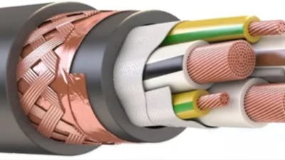
Design Response: Type 241 cables for OT must have: (1) Heavy-duty outer jacket (3.5–4.0 mm thickness, vs 2.5–3.0 mm for standard), (2) Internal reinforcement braid that constrains radial deformation under crush, (3) Materials formulated to maintain mechanical properties even after partial crushing (elastic recovery, not permanent deformation).
4. Vertical Shaft Tension: Cable Self-Weight and Breaking Load Analysis
Cable Weight Calculation: A 3×95mm² Type 241 cable weighs approximately 8.5–9.5 tonnes per kilometer. When deployed vertically in a shaft, the cable’s self-weight creates tensile stress in conductors and internal support members. For a 500-meter vertical drop (typical for OT shaft sections), the cable’s own weight load is:
Weight Load = 500 m × 8.5 tonnes/km = 4.25 tonnes (≈ 42.5 kN)
Tensile Strength Requirement: The cable’s breaking strength (measured as the maximum tensile load before conductor failure) must be at least 5–10× the expected operational load to provide safety margin. For a 42.5 kN self-weight load, the cable’s breaking strength should be ≥ 200–300 kN.
Conductor Cross-Section Implication: A 3×95mm² Type 241 has total conductor breaking strength approximately 250–300 kN (depending on material and construction). For vertical deployments exceeding 700–800 meters, larger conductor sizes (3×120mm² or 3×150mm²) may be required to maintain adequate tensile safety margin.
Kevlar/Aramid Support Consideration: Some arctic-grade Type 241 designs incorporate Kevlar (aramid) load-bearing members within the cable structure to share tensile load with copper conductors, reducing stress on electrical conductors and preventing conductor stretching that could thin insulation.
5. Arctic-Geothermal Thermal Cycling: Temperature Stress Coupling
Temperature Extremes: OT surface experiences -40°C winter extremes. Underground at 1,300 m depth (geothermal gradient ~25°C per km), baseline temperature is ~15°C. However, equipment operation generates heat—underground substations, motor drives, and ore handling equipment can create localized 35–40°C zones. Cables physically transition between these zones (from -40°C surface hoist shaft to +35°C underground working areas) multiple times per winter, creating thermal cycling stress.
Thermal Stress Physics: Copper conductors (thermal expansion coefficient ~17 ppm/K) and elastomeric jackets (200+ ppm/K) expand/contract at vastly different rates. Over a 70°C temperature swing (-40°C to +30°C), copper expands by 1.2 mm per meter, while elastomer expands 14 mm per meter. This differential creates internal delamination stress between layers. After 50–100 thermal cycles, micro-voids form at material interfaces, weakening mechanical bonds and accelerating electrical breakdown (partial discharge initiation).
Partial Discharge Risk at 11kV: At 11kV nominal (16 kV peak transient), even microscopic voids in insulation become discharge points. Partial discharge creates electrical erosion that rapidly propagates internal cracks. An insulation system weakened by thermal cycling becomes increasingly susceptible to PD inception.
Design Mitigation: OT specification cables require: (1) Synchronized elastomer materials—jacket, insulation, and pilot core cradle all using identical formulations with matched thermal expansion, (2) Anti-delamination interlayers using polymers with intermediate thermal expansion to absorb stress, (3) Partial discharge testing at elevated voltage after thermal cycling to verify insulation integrity.
6. Mechanical Suitability: Material and Design Requirements for OT
Super Heavy-Duty Jacket Specification: Rather than standard PCP, OT-rated Type 241 cables require: (1) Premium CPE or PUR elastomer with enhanced tear resistance, (2) Jacket thickness 3.5–4.0 mm (vs 2.5–3.0 mm standard), (3) Internal reinforcement braid (open-weave aramid or high-strength nylon) constraining radial deformation.
Insulation Grade Selection: For the combination of high voltage (11kV), extreme temperature cycling, and mechanical stress, cables should use EPR insulation (not XLPE). EPR maintains flexibility at -40°C better than XLPE, critical for arctic conditions. Additionally, EPR naturally has lower partial discharge inception voltage (PDIV) at room temperature but better thermal cycling tolerance.
Pilot Core Tensile Verification: The central pilot core must incorporate Kevlar or other high-strength support members, not simple copper strands. A 16 mm² Kevlar-supported pilot core can withstand 2,000–2,500 N tensile load, essential for vertical shaft deployment where the pilot core itself may experience significant tension.
7. Ampacity Baseline: Standard AS/NZS 3008 Reference Conditions
Reference Assumptions: AS/NZS 3008 ampacity tables assume: (1) Ambient temperature 40°C, (2) Conductor maximum operating temperature 90°C, (3) Cable in free air (not bundled or enclosed), (4) Natural convection cooling only, (5) Single cable (not grouped with others), (6) Steady-state continuous operation.
Baseline Ampacity for Type 241 3×95mm²: Under reference conditions, a typical 3×95mm² Type 241 cable is rated 240–260 A at 11kV.
Critical Note—Nameplate vs Field Conditions: The 240–260 A rating is purely theoretical for underground mining applications where none of the reference assumptions hold true. Underground deployment requires substantial derating through application of correction factors.
8. Derating Factor Application: Underground Ventilation and Heat Dissipation
Thermal Environment of Underground Cables: Underground cables in OT are deployed in several configurations: (1) Fixed on cable trays in tunnel walls (partially enclosed, limited airflow), (2) Coiled on mobile substation reels (multi-layer wrapping, self-insulating), (3) Through floor ducts (enclosed, air velocity <0.5 m/s). In all configurations, heat dissipation is far worse than free-air assumptions.
Derating Factor Calculation: AS/NZS 3008 provides derating tables for various configurations. For underground mining typically: (1) Cable on tray in enclosed space (dusty, limited ventilation): derating factor 0.5–0.6, (2) Cable in flexible conduit (air circulation restricted): derating factor 0.4–0.5, (3) Multi-layer coil on reel: derating factor 0.4–0.5.
Example Calculation—3×95mm² Type 241: Baseline ampacity: 250 A. Applied to underground tray installation: 250 A × 0.55 (derating factor) = 137.5 A actual safe ampacity. This is a 45% reduction from nameplate rating.
Ambient Temperature Derating: For underground work at 35°C ambient (vs 40°C reference), minimal additional derating applies. However, if localized heating from nearby equipment creates pockets exceeding 40°C, additional derating becomes necessary. A conservative design assumes 45°C ambient for underground locations near substations, requiring additional 5–10% ampacity reduction.
Rio Tinto’s design standard for OT requires a minimum 0.5 combined derating factor (all environmental and thermal effects combined) when specifying 11kV cable ampacity. This means nameplate ratings should be assumed to be only 50% available in actual operational conditions. Electrical designers must size cables for only 50% of their theoretical rating.
9. Complete Technical Specification: Type 241 11/11kV for OT Expansion
| No. Cores × Cross-sec. | AWG Equiv. | Outer-Ø (mm) | Cu Weight (kg/km) | Total Weight (kg/km) | Ampacity @ 40°C (A) | Field Ampacity @ 0.5 Derating |
|---|---|---|---|---|---|---|
| 3×50 + 3×(50/3) + 1×16 | 1/0 AWG | 58–62 | ~1,650 | ~6,800 | 165 | ~82 A |
| 3×70 + 3×(70/3) + 1×16 | 2/0 AWG | 64–68 | ~2,300 | ~8,200 | 205 | ~103 A |
| 3×95 + 3×(95/3) + 1×16 | 3/0 AWG | 70–74 | ~3,100 | ~9,600 | 250 | ~125 A |
| 3×120 + 3×(120/3) + 1×16 | 4/0 AWG | 75–79 | ~3,850 | ~11,200 | 290 | ~145 A |
10. Mobile Substation Deployment: Reel Heat and Continuous Rating
Mobile Substation Configuration: OT underground uses transportable substations (mobile units powered by diesel or electric drive) that position themselves at extraction zones to provide 3.3kV feeders to LHD equipment. The 11kV cable connects from the main underground distribution point to the mobile substation, often spooled on the unit’s own cable reel. During operation, the cable carries load continuously, generating heat within the coil.
Self-Heating in Coiled Cable: When a cable is wound on a reel and carrying current, the conductor resistance generates heat. In a multi-layer coil, this heat is trapped—inner layers are insulated from external cooling by outer layers. Heat dissipation from a coiled cable on a reel is extremely poor, equivalent to 0.4–0.5× derating factor when heat generation is significant.
Thermal Model—Coiled Cable on Reel: For a 3×95mm² cable carrying 100 A on a mobile substation reel (typical load for LHD feeder duty), the conductor self-heating power loss is:P_loss = I² × R_conductor = (100)² × (resistance per meter) ≈ 2–3 kW per 1,000 meters of cable on reelThis dissipates entirely within the cable sheath, raising internal temperature 15–25°C above ambient. For a 35°C underground ambient, the cable can reach 50–60°C internal temperature, well above design assumptions.
Continuous Rating Derating: Rio Tinto’s specification requires that 11kV cables deployed on mobile substations use an additional 0.7–0.8 derating factor (beyond the base 0.5 for underground installation) to account for self-heating. This results in a combined 0.35–0.4 effective derating factor.
11. Earth Continuity Monitoring at 11kV: High-Voltage Pilot Core Challenges
Pilot Core Function at 11kV: Unlike low-voltage systems where pilot core resistance monitoring is straightforward, 11kV systems require careful design because: (1) The pilot core is exposed to 11kV potential difference relative to earth, (2) High-voltage stress can ionize insulation around the pilot core, (3) Pilot core test signals can interact with system transients and noise.
Pilot Core Insulation: The pilot core must be insulated from adjacent power conductors by a robust semiconductive cradle and EPR layer (~1.5 mm combined thickness) to withstand 11kV stress without breakdown. Standard low-voltage pilot core insulation (typically <1.0 mm) is inadequate.
Pilot Core Test Signal Frequency: Earth continuity relays for 11kV systems typically use 100–200 Hz test frequency (higher than low-voltage systems’ 50 Hz) to reduce capacitive coupling and noise on the pilot core signal. The cable must be verified to carry this test signal reliably without crosstalk to power conductors.
Specification for OT: Type 241 cables for OT must specify: (1) Pilot core insulation thickness ≥1.5 mm (verified by physical measurement), (2) Pilot core to power conductor capacitance <1.0 nF per meter (tested), (3) Pilot core resistance profile <0.5 Ω per meter at operating temperature.
12. Conclusion: OT Expansion Power System Engineering Excellence
Summary—Integrated Design Strategy for OT 11kV Cables: (1) Mechanical suitability: Heavy-duty jacket (3.5–4.0 mm), internal reinforcement braid, crush-resistant geometry, (2) Thermal capability: Synchronized elastomer materials, anti-delamination interlayers, partial discharge testing post-cycling, (3) Ampacity: Conservative 0.5 combined derating factor in design calculations, additional 0.7–0.8 factor for reel deployment, (4) Vertical shaft deployment: Tensile strength verification for >500 m drops, potential Kevlar support reinforcement, (5) Earth continuity: 1.5 mm pilot core insulation, 100+ Hz signal compatibility, <0.5 Ω/m baseline resistance.
Design Workflow for OT Projects: (1) Confirm exact operational scenario (fixed tray vs reel vs shaft), (2) Calculate load current and multiply by 2.0–2.5 to find required nameplate ampacity (inverse of derating), (3) Select conductor size that meets thermal and mechanical requirements, (4) Specify arctic-grade materials, (5) Require third-party testing for mechanical, thermal, and electrical verification, (6) Plan for continuous monitoring (monthly IR trending, annual tension verification).
Feichun Special Cable provides purpose-designed Type 241 11/11kV cables for Rio Tinto’s Oyu Tolgoi expansion, including: heavy-duty mechanical adaptation, arctic thermal cycling qualification, earth continuity high-voltage compatibility, complete AS/NZS 1802 testing documentation, and ongoing field support for underground block cave operations.
References & Sources
- AS/NZS 1802:2012, “Fixed electric cables—General purpose cables for underground mining,” Standards New Zealand and Standards Australia.
- AS/NZS 3008.1.1:2017, “Electrical installations—Selection of cables—Cables for installation,” Standards New Zealand and Standards Australia.
- Rio Tinto Engineering Standards, “Underground High-Voltage Distribution Cable Specification for Block Caving Operations,” Internal Technical Document, 2024.
- Feichun Special Cable Research & Development Team, “11kV Type 241 Cable Engineering for Oyu Tolgoi Block Cave Expansion,” Technical Report, 2025.