
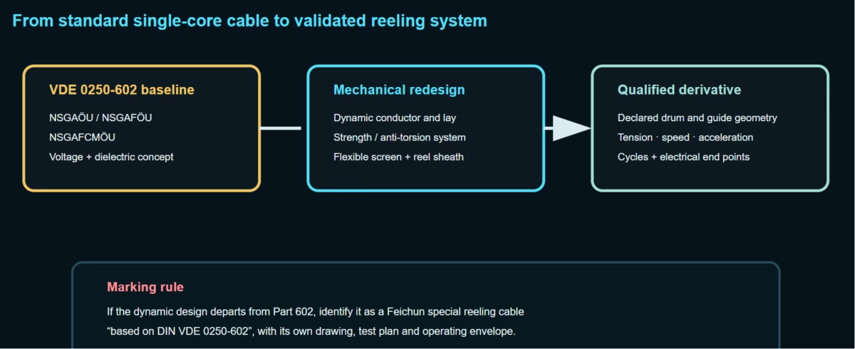
Can NSGAÖU, NSGAFÖU and NSGAFCMÖU Be Developed as Reeling Cables?
Yes—but only as application-specific derivatives with a controlled change of designation and a full dynamic qualification program. Standard DIN VDE 0250-602 versions are special rubber-insulated single-core cables for fixed or limited movement; they do not automatically possess the conductor stability, tensile load sharing, torsion control, flexible screening, abrasion resistance, drum heat behavior or verified bending life required for continuous motorized reeling.
Direct answer: retain the electrical concept, redesign the mechanical system
A cable may be electrically derived from NSGAÖU, NSGAFÖU or NSGAFCMÖU, but once conductor construction, screen, reinforcement, sheath system or dimensional design is changed for repeated drum duty, it must be described as “based on DIN VDE 0250-602” or by a manufacturer-specific type—not represented as an unchanged standard VDE 0250-602 cable.
Class 1 or Class 2 conductors are unsuitable starting points for continuous reeling. Use only for static payout or very limited movement where the approved duty permits.
Class 5 construction is the most plausible electrical baseline, but high-cycle reeling still requires strand, lay, separator, support and sheath redesign.
The screened electrical concept can be retained, but the Part 602 concentric wire screen must not be assumed to survive repeated reverse bending.
For continuous crane, mining or conveyor motion, an NSHTÖU or NTS/(N)TSCGEWÖU family is normally the safer standards route.
Designation control: adding a Class 6 conductor, central strength member, textile reinforcement, flexible braid, PUR sheath or multicore lay may be a good engineering decision, but it changes the standardized construction. The marking and certificate must show that distinction.
Why a flexible conductor does not make a reeling cable
| Stress mechanism | Standard NSGAFÖU/NSGAFCMÖU assumption | Continuous reel reality | Required design response |
|---|---|---|---|
| Repeated bending | Routing and occasional movement at the published bend radius | Thousands or millions of curvature reversals at the drum and guides | Dynamic strand geometry and verified cycle test. |
| Axial tension | Installation pull primarily carried by the copper within stated limits | Suspended length, acceleration, drag and reel torque act every cycle | Dedicated strength member or load-sharing braid where required. |
| Torsion | Not a defining continuous duty | Fleet angle, guide rollers and misalignment repeatedly twist the cable | Torque-balanced lay and anti-torsion reinforcement. |
| Screen fatigue | Metal wire screen selected for the standard construction | Screen wires experience alternating tensile/compressive strain | Flexible individual-core screen or reeling-qualified screen system. |
| Radial pressure | Normal installation contact | Layer pressure and tension compress lower wraps on the drum | Crush-resistant, geometrically stable core and sheath system. |
| Abrasion | General mechanical protection | Drum spokes, guide surfaces, grit and crossovers act repeatedly | High tear/abrasion sheath and smooth reel hardware. |
| Heat dissipation | Installed route has defined ambient and grouping | Multiple wound layers trap conductor and solar/motor heat | Reeled-current rating and drum-layer derating. |
Three technically defensible development routes
| Route | Starting point | Intended movement | Required changes | Designation |
|---|---|---|---|---|
| A — Low-cycle payoff/retrieval | NSGAFÖU Class 5 electrical construction | Manual or slow intermittent winding with controlled tension and no severe reverse bending | Verify strand lay, separator, sheath abrasion and actual reel radius; cycle-test the declared duty. | Part 602 type only if construction remains compliant; movement claim is an additional manufacturer declaration. |
| B — Reinforced single-core reel derivative | NSGAFÖU voltage and dielectric concept | Repeated motorized reeling where the system architecture truly requires one conductor per cable | Reeling conductor, load-bearing/anti-torsion layer, high-abrasion sheath, drum thermal design and full dynamic tests. | Feichun special type, based on VDE 0250-602; not plain NSGAFÖU. |
| C — Screened single-core reel derivative | NSGAFCMÖU 3.6/6 kV electrical concept | Special screened single-core circuit with engineered synchronized reels | Redesign screen for fatigue, prove transfer/fault performance, add strain relief and field-control termination. | Feichun screened reeling type based on Part 602; separate qualification. |
| D — True multicore reel cable | System requirement rather than Part 602 geometry | Crane, stacker/reclaimer, ship loader, excavator or conveyor with frequent movement | Balanced multicore lay, PE/monitoring cores, optional FO/control, anti-torsion reinforcement and reeling sheath. | NSHTÖU, NTS/(N)TSCGEWÖU or appropriate manufacturer special family. |
For three-phase AC, a balanced multicore reeling cable normally controls inductance, magnetic field, phase geometry and reel synchronization better than three independent single-core reels. Single-core reeling should be selected only after the system designer proves why it is necessary.
Electrical baseline that may be retained from Part 602
| Base family | Part 602 voltage classes | Base conductor range | Dynamic-development status |
|---|---|---|---|
| NSGAÖU | 0.6/1, 1.8/3 and 3.6/6 kV | Class 1: 1.5–10 mm²; Class 2: 16–300 mm²; 3.6/6 kV max. 185 mm² | Not recommended for continuous reeling because Class 1/2 conductor fatigue governs. |
| NSGAFÖU | 0.6/1, 1.8/3 and 3.6/6 kV | Class 5: 1.5–300 mm²; 3.6/6 kV max. 185 mm² | Candidate electrical baseline; reeling performance remains unproven until qualified. |
| NSGAFCMÖU | 3.6/6 kV | Class 5 up to 185 mm² | Electrical-screen baseline only; metallic screen requires fatigue redesign or proof. |
| Rated voltage U0/U | Common base AC test voltage | Dynamic cable additional question |
|---|---|---|
| 0.6/1 kV | 2.5 kV in published Part 602 product literature | Is voltage applied during bending test, and what electrical monitoring is continuous? |
| 1.8/3 kV | 6 kV | Is the derivative used on a 3 kV circuit or as robust cable in a lower-voltage system? |
| 3.6/6 kV | 11 kV | Are semiconductive layers, screen/PE connection and post-cycle PD/voltage tests specified? |
Dynamic conductor: strand diameter alone does not determine reel life
Repeated bending causes each strand to migrate, slide and alternate between tensile and compressive strain. A successful reeling conductor must coordinate strand diameter, bunch construction, direction of lay, lay length, compaction, separator friction and the stiffness of surrounding rubber. Merely changing “Class 5” to “Class 6” can make a conductor more flexible while reducing torsional stability.
| Variable | Benefit | Possible penalty | Qualification evidence |
|---|---|---|---|
| Smaller strand diameter | Reduces strain per strand at a given bend radius. | More interfaces, friction and process sensitivity. | Strand-break inspection and resistance trend after cycling. |
| Uniform-lay bunching | High flexibility and reduced conductor diameter. | Can be unstable under torsion and axial compression. | Reeling plus torsion test on finished cable. |
| Alternating lay | Improves torsion and compression stability. | Crossing points increase friction and may accelerate breaks. | Reverse-bend endurance at representative tension. |
| Separator tape | Controls adhesion and permits strand movement. | Wrinkling or excessive overlap can create hard spots. | Post-cycle dissection and interface inspection. |
| Compaction | Reduces diameter and improves geometric stability. | Excess compaction limits strand migration. | Process capability and cyclic resistance stability. |
| Tinned copper | Supports corrosion resistance and termination compatibility. | Tinning does not increase fatigue life by itself. | Material and strand-surface inspection. |
Insulation and electric-field control under cyclic deformation
| Layer/interface | Reeling risk | Engineering response | Verification |
|---|---|---|---|
| Conductor/insulation | Strand impressions and local field enhancement increase with bending pressure. | Smooth conductor screen where voltage design requires; compatible separator and extrusion pressure. | Section microscopy, voltage test and PD test where applicable. |
| 3GI3/EPR dielectric | Fatigue, thermal ageing and local compression occur together. | Compound cure and modulus optimized for the declared temperature and radius. | Mechanical ageing plus representative flex test. |
| Insulation screen | Cracks or separation can create local discharge sites. | Flexible semiconductive compound with controlled adhesion and elongation. | Interface dissection and electrical test after cycles. |
| Bedding | Hard fillers or discontinuities create pressure points. | Continuous compatible elastomer and smooth concentric geometry. | Crush/reeling test and dimensional section. |
| Termination transition | Cyclic bending may concentrate at the end of the gland or stress control. | Long strain-relief geometry and fixed transition outside the active bend zone. | Installation validation at both reel and equipment ends. |
Medium-voltage boundary: a 3.6/6 kV reeling derivative should not rely on an optional or poorly defined field-control layer. The approved drawing must explicitly state conductor screen, insulation, outer semiconductive layer, screen/earth interface and termination system.
Why the NSGAFCMÖU screen must be re-engineered for reel duty
Part 602 defines a concentric serving of 106–110 copper wires in total, nominally 0.6 mm each, with two untinned identification wires. That arrangement is meaningful for the standard cable, but repeated bending under tension can fatigue metallic screens. Reeling designs therefore need a screen selected for cyclic strain, not simply the original wire count.
| Screen concept | Dynamic behavior | Electrical consideration | Use decision |
|---|---|---|---|
| Original Part 602 wire serving | Large wires may experience significant alternating strain. | Standard construction identity, but no universal reel-cycle claim. | Only after finished-cable reeling qualification. |
| Fine-wire braid | Allows crossing and redistribution during bending. | Coverage, DC resistance, transfer impedance and fault duty must be stated. | Useful for EMC/continuity where properly engineered. |
| Counter-helical fine-wire screen | Can balance torque and reduce local strain. | Lay angles and longitudinal continuity govern performance. | Project-specific dynamic screen. |
| Semiconductive rubber core screen + PE contact | Eliminates fatigue-prone metal directly around each power core in many MV trailing designs. | Touch protection, radial field and fault-current return are integrated with PE architecture. | Preferred principle in many true MV reeling families. |
| Overall metallic screen | Frequent bending produces tensile and pressure forces across the overall layer. | May provide EMC but can become a mechanical weak plane. | Avoid unless a reel-qualified construction proves endurance. |
Tension, elongation and anti-torsion reinforcement must work together
A braid is useful only when its load–elongation curve is coordinated with the copper. If the braid engages too late, the conductor has already stretched; if it is too stiff, termination loads and local buckling can increase. A central support element carries tension earlier, but it also changes cable geometry and can be unsuitable for some reeling layouts.
| Load source | Approximate engineering model | Design control |
|---|---|---|
| Suspended cable | Weight per metre × vertical hanging length | Strength member, reel torque and safe maximum payout. |
| Acceleration/deceleration | Moving cable mass × acceleration, including reel dynamics | Drive control, tension regulation and transient allowance. |
| Guide/friction drag | Route- and hardware-dependent resistance | Roller alignment, bearing condition and low-friction route. |
| Radial sidewall pressure | p ≈ T / R | Minimum guide radius and maximum cable tension. |
| Torsion | Fleet angle, offset guides, reel misalignment and cable torque | Anti-torsion braid, lay balance and guide geometry. |
| Layer compression | Upper-wrap tension transmitted into lower drum layers | Level-wind quality, layer count and crush-resistant design. |
Drum core, guide rollers and reverse bending determine strain
| Geometry | Risk | Required project data |
|---|---|---|
| Drum core diameter | Too small a core raises conductor, screen and sheath strain every revolution. | Root/core diameter, cable OD tolerance and dynamic minimum bend radius. |
| Guide-sheave diameter | A small sheave can govern fatigue even when the reel core is large. | Every sheave and entry-bell radius in the route. |
| S-bend distance | Rapid curvature reversal prevents internal layers from recovering. | Distance between opposite-direction bends and exact cable path. |
| Fleet angle | Creates torsion, flange rubbing and poor layer placement. | Reel width, guide position and lateral travel. |
| Crossovers | Localized crushing and abrasion at random-wind intersections. | Winding pattern, tension and permitted layers. |
| Transition fixation | Hard clamping at an active bending point concentrates strain. | Strain-relief length and fixed-to-flex transition. |
Different reel systems impose different failure mechanisms
| Reel system | Dominant cable stress | Design priority |
|---|---|---|
| Monospiral reel | High winding tension, guide-induced torsion, high speed and possible S-bend at centre feed | Stable round geometry, dynamic tension rating and reverse-bend test. |
| Level-wind reel | Traverse-guide bending and torsion; precise layer placement across wide drum | Fleet-angle control, abrasion-resistant sheath and thermal layer limit. |
| Random-wind reel | Crossovers, variable contact pressure and smaller effective radius | Crush resistance and controlled torque; avoid excessive layers. |
| Vertical/spreader reel | Large hanging weight, acceleration and drum-spoke abrasion | Early-engaging strength member and robust strain-relief termination. |
| Spring-operated reel | Continuously varying spring tension and many short cycles | Match spring torque curve to cable tension envelope. |
| Motor torque reel | Drive-control transients and possible over-tension during starts/stops | Closed-loop torque control, braking logic and overload protection. |
A cable wound on the drum cannot use free-air ampacity unchanged
| Input | Thermal effect | Engineering action |
|---|---|---|
| Number of energized layers | Inner wraps lose convective and radiative cooling. | Calculate the worst wound condition; define maximum energized layers. |
| Duty cycle | Short peaks may be thermally acceptable while continuous load is not. | Use time-current profile and cable thermal time constant. |
| Conductor AC resistance | Temperature and skin/proximity effects raise loss. | Use operating-temperature AC values, not only 20°C DC resistance. |
| Metal drum | Can absorb heat but may also introduce magnetic/eddy-current effects with single-core AC cable. | Evaluate drum material and ensure phase arrangement does not create hazardous heating. |
| Solar exposure | Raises sheath and drum temperature before electrical loading. | Include solar gain and colour/absorptivity in outdoor design. |
| Reel motor/brake heat | Local machinery heat warms adjacent cable layers. | Measure or model actual enclosure/drum temperature. |
Single-core AC warning: reeling separate phase conductors on independent ferromagnetic drums can create unequal impedance, large magnetic loops and local heating. Three-phase geometry, reel material, bonding and synchronization require system-level analysis.
Dynamic qualification must reproduce the actual reel system
| Test | Replicated stress | Recorded parameters | Post-test examination |
|---|---|---|---|
| Reeling/unreeling | Drum curvature, layer pressure, tension and sheath contact | Core/guide diameter, length, layers, tension, speed, acceleration and cycles | Resistance, sheath, conductor strands, screen and dimensions. |
| Roller bending | Repeated guide-sheave flexing under tensile load | Roller diameter, spacing, moving distance, load and cycles | Broken strands, electrical continuity and interface damage. |
| Reverse/S-bend | Rapid change in curvature direction | Both radii, distance between bends, load and temperature | Core migration, screen fatigue and sheath buckling. |
| Torsion under tension | Fleet angle and guide misalignment | Angle per length, torque, axial force and cycle count | Corkscrew, layer displacement and screen continuity. |
| Abrasion | Drum/guide contact with contamination | Counterface, pressure, travel and environmental medium | Sheath loss, cracks and exposed reinforcement. |
| Crush/radial pressure | Lower-layer compression on drum | Load, contact area, duration and temperature | Diameter recovery and dielectric integrity. |
| Energized thermal cycle | Electrical heating during wound and paid-out states | Current, conductor/sheath temperatures and layer arrangement | Ageing, resistance drift and electrical tests. |
| Environmental dynamic test | Low temperature, oil, water spray, UV/ozone plus movement | Conditioning and mechanical duty | Cracks, swelling, hardness and electrical integrity. |
A current crane-cable technical catalogue describes dedicated roller-bending, torsional and reeling rigs, including representative cable travel and tensile loading. Those rig capacities are examples of test capability—not universal cycle counts or acceptance thresholds for a Feichun product.
What should count as Pass, Hold or Fail?
| Finding | Disposition | Reason |
|---|---|---|
| No interruption, approved resistance trend, no prohibited strand/screen damage, sheath intact, all electrical tests passed | PASS | Declared cycle duty is supported by mechanical and electrical evidence. |
| Minor cosmetic wear within an approved limit, electrical results stable, no layer exposure | ENGINEERING REVIEW | Wear rate and remaining sheath margin must be correlated with service life. |
| Conductor-resistance step change or intermittent continuity during motion | FAIL | Indicates strand breakage, termination movement or conductor instability. |
| Screen resistance/transfer behavior changes materially or wires break | FAIL | EMC, touch protection or fault-current function may be compromised. |
| Corkscrewing, diameter growth, sheath buckling or core migration | FAIL | Internal torque balance and mechanical geometry are unstable. |
| Cracks, exposed reinforcement or unacceptable abrasion depth | FAIL | Environmental and mechanical barrier is lost. |
| Post-cycle voltage/PD test fails | FAIL | Dielectric system was damaged by dynamic stress. |
| Test omitted actual S-bend, tension, temperature or drum radius | INVALID FOR CLAIMED DUTY | The test does not represent the intended operating envelope. |
Numeric limits for cycles, resistance change, abrasion depth and permitted broken strands must be fixed in the approved qualification plan. This article does not invent universal values where no universal rule exists.
Failure patterns and corrective actions
| Symptom | Likely mechanism | Investigation | Corrective action |
|---|---|---|---|
| Repeated failure at drum tangent | Core diameter too small or excessive tension | Measure actual OD, core radius and dynamic tension | Increase radius, reduce torque or redesign cable. |
| Failure near guide | Guide radius, misalignment or S-bend governs | Map curvature and fleet angle through full travel | Reposition/enlarge guide and qualify new path. |
| Corkscrew after payout | Internal torque imbalance or forced twist | Check lay direction, guide rotation and installation orientation | Correct installation or use torque-balanced construction. |
| Broken screen with intact conductor | Metallic screen has lower fatigue margin | Continuity, resistance, X-ray/dissection and bend history | Adopt flexible screen or change radius/tension. |
| Lower-layer flattening | Excess radial pressure or random-wind crossover | Layer tension, drum pattern and crush test | Level-wind control, fewer layers or stronger geometry. |
| Hot wound reel | Free-air ampacity applied to reeled cable | Thermal imaging and conductor-temperature model | Derate current, pay out cable or redesign reel. |
| Sheath cuts at flange/spokes | Sharp hardware or uncontrolled lateral movement | Inspect all contact surfaces and fleet angle | Radius/polish hardware and improve level winding. |
When the correct answer is a different cable family
| Duty | Preferred family | Why it is stronger than a Part 602 derivative |
|---|---|---|
| 0.6/1 kV multicore drum reel | NSHTÖU under DIN VDE 0250-814 or a declared high-dynamic derivative | The product family is explicitly a rubber flexible cable used for reeling, with multicore geometry and mechanical sheath system. |
| 0.6/1 kV heavy trailing/reeling | NTS…WÖU family based on DIN VDE 0250-813 | Heavy-duty trailing architecture and broader mechanical design options. |
| 3.6/6 kV and above MV reeling | (N)TSCGEWÖU / (N)TSKCGEWÖU and application-specific crane/mining types | Balanced power cores, defined semiconductive field control, PE architecture and optional FO/control elements. |
| Spreader vertical reel | Support-element reeling cable | Central or engineered load-bearing system carries vertical tension from the beginning. |
| VFD/EMC dynamic cable | Reeling-qualified screened multicore cable | Symmetrical geometry and flexible screen are designed for both EMC and bending. |
| Festoon only | Flat or round festoon cable matched to trolley geometry | Festoon bending and suspension differ from drum winding; a reel derivative may be unnecessarily stiff or unstable. |
Do not force the legacy designation: retaining “NSGAFÖU” in a specification is not beneficial if the operating system needs a multicore, torque-balanced, tensile-supported cable. Select by mechanical duty first, then preserve the required electrical parameters.
Application-oriented development matrix
| Machine/system | Likely reel stress | Recommended route | Data that decides the design |
|---|---|---|---|
| Ship-to-shore crane | High speed, reverse bending, VFD noise and salt/UV | True multicore LV/MV crane reeling family, not independent NSGAFÖU phases | Travel, reel type, speed, acceleration, route, voltage and FO/control. |
| RTG/RMG crane | Frequent starts, compact guides and outdoor heat | Torque-balanced reeling cable with application-specific screen/PE | Duty profile, layer count, VFD waveform and drum dimensions. |
| Stacker/reclaimer | Long payout, dust, abrasion and random/level winding | NTS/(N)TSCGEWÖU-class heavy reeling design | Route length, vertical component, drag, tension and dust/oil. |
| Spreader | High vertical tension and rapid lifting cycles | Central-support or dedicated spreader reeling cable | Hanging length, acceleration, payload motion and termination. |
| Temporary industrial feeder | Low-speed intermittent retrieval, controlled surface | Possibly NSGAFÖU-derived Route A after cycle proof | Actual movements, radius, tension, energized state and environment. |
| Special DC single-core reel | High current, thermal layering and two-pole synchronization | Reinforced single-core derivative only after system analysis | DC voltage/current, polarity reels, drum material and touch protection. |
Feichun Cable engineering and certification boundary
Engineered for maximum safety in demanding environments, our cable systems comply with global standards including ATEX, IECEx, VDE, CE, UKCA, EAC, and the Russian Fire Safety Certificate. They are the trusted choice for heavy-duty mining equipment, ship-to-shore cranes, RTG/RMG cranes, and conveyor systems where high reliability is non-negotiable.
Certificate applicability must be verified for the exact derivative, manufacturing site, certificate number, validity period and project. A cable described as “based on DIN VDE 0250-602” does not automatically hold a VDE certificate for the modified reeling construction, nor does a dynamic test establish any unrelated certification.
Frequently asked questions and RFQ checklist
Can standard NSGAFÖU run on a motorized reel?
Only if the manufacturer has qualified the exact cable for the specified reel, tension, radius, speed, temperature and cycle count. Class 5 alone is not sufficient evidence.
Can NSGAÖU be made more flexible?
Changing its Class 1/2 conductor to a reeling conductor changes the standardized family. The resulting cable needs a new special-type designation.
Can the NSGAFCMÖU screen be retained?
It can be evaluated, but the original screen must pass representative fatigue and electrical tests. A flexible screen or different PE/screen architecture may be safer.
Is a smaller bend radius always better?
No. It helps compact machinery but increases strain and usually reduces service life. The selected radius must be qualified, not merely physically achievable.
How many reel cycles should be specified?
Use the machine duty and required service interval. There is no universal cycle count; the test must state what constitutes one cycle and reproduce load, radius and temperature.
Can reeling speed be specified without acceleration?
No. Starts, stops and emergency braking can create higher tension than steady travel. Speed, acceleration, jerk and reel control must be supplied together.
Can free-air ampacity be used on the reel?
Not without thermal verification. Wound layers restrict cooling and can require substantial current derating.
What is the safest three-phase solution?
A balanced multicore reeling cable is normally preferred because phase geometry, PE system, torque and reel synchronization are controlled in one construction.
Technical sources and argument support
- VDE VERLAG — DIN VDE 0250-602:1985-03: valid product standard for NSGAÖU, NSGAFÖU and NSGAFCMÖU special rubber-insulated single-core cables.
- VDE VERLAG — DIN VDE 0250-814:1985-02: valid standard for NSHTÖU rubber flexible cable, the direct standards reference for many 1 kV reeling applications.
- VDE VERLAG — DIN VDE 0298-3:2006-06: current use guidance for cables and insulated conductors in power installations.
- DIN VDE 0298-4:2023-06 and its 2023-10 corrigendum: current ampacity route; reeled-state thermal conditions still require specific assessment.
- IEC 60228:2023: current conductor-class, cross-section and resistance framework; conductor class is not a reeling-life classification.
- IEC 60332-1-2:2025: current single-cable flame-propagation test; it does not prove dynamic reel endurance.
- IEC 60811-404:2012 and IEC 60811-403:2012: oil-immersion and ozone-resistance material test methods.
- Crane Cables General Catalogue 2024: engineering evidence on reeling tension, bending radius, screening, conductor lay, support elements and dedicated roller-bending/torsion/reeling test rigs.
- Cables for Reeling Systems technical catalogue: comparison of monospiral, spreader, random-wind and level-wind stresses, including tension, torsion, S-bending, abrasion and thermal-layer concerns.
- IEC 61316:2021: industrial cable-reel standard for the defined low-voltage/current scope; useful for reel assembly boundaries but not a universal high-power crane-cable standard.
Standards and catalogues are copyrighted; this article summarizes verified scope and engineering principles without reproducing controlled test tables. No Feichun reel speed, bending cycles, tensile rating, OD, mass or minimum radius is claimed because no project-specific construction has been supplied. Those values must be established in the approved Feichun drawing and qualification plan.


