
VDE 0250 Part 602 Cable: Complete Engineering Guide to NSGAÖU, NSGAFÖU and NSGAFCMÖU
DIN VDE 0250-602 defines special rubber-insulated single-core cables for power installations—not welding leads, general XLPE distribution cables or heavy-duty multicore trailing cables. Its three construction families combine tinned copper conductors, 3GI3 rubber insulation and a 5GM3 rubber outer covering; the screened NSGAFCMÖU design adds a defined wire screen and outer sheath. Correct selection requires the full type designation, voltage class, conductor construction, installation method, touch-protection strategy and short-circuit duty.
What is VDE 0250 Part 602?
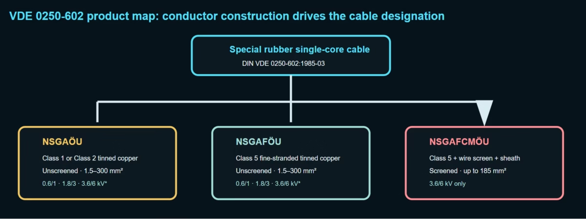
DIN VDE 0250-602 is the product standard for “special rubber-insulated single-core cables.” It covers NSGAÖU with solid or stranded conductor, NSGAFÖU with fine-stranded conductor, and NSGAFCMÖU with fine-stranded conductor, metallic screen and outer sheath. A complete designation must include the cable type, core size and rated voltage.
The covered constructions are single-core power cables. A multicore rubber trailing cable belongs to a different product family and standard.
0.6/1 kV, 1.8/3 kV and 3.6/6 kV, subject to the cable-family and cross-section limits.
Extruded vulcanized rubber insulation, normally implemented as an EPR/EPDM-family compound.
Oil-resistant rubber outer covering or sheath. This does not automatically establish LSZH performance.
Most common search error: H01N2-D/H01N2-E welding cable is standardized under EN 50525-2-81, while VDE 0250-602 covers the NSGA… family. The two products have different rated voltages, conductor constructions, installation duties and design intent.
A 1985 issue can still be a valid standard
| Item | Verified information | Procurement consequence |
|---|---|---|
| Full reference | DIN VDE 0250-602 (VDE 0250-602):1985-03 | Write the complete number and date; “VDE 0250 cable” is not sufficient. |
| Official title | Insulated power cables — special rubber-insulated single-core cables | Confirms that the document is not a general rubber-cable catalogue. |
| Official status | Marked “Gültig” (valid) by VDE VERLAG when checked in 2026-08 | Age alone is not evidence of withdrawal. |
| Issue date | March 1985; effective from 1 March 1985 | Original clauses reference document names current at that time. |
| Companion basis | Additional to the general requirements of DIN VDE 0250-1 | Part 602 must not be used as a stand-alone eight-line specification. |
| Use guidance | DIN VDE 0298-3; ampacity is evaluated with current installation rules such as DIN VDE 0298-4:2023-06 and Corrigendum 1:2023-10. | Separate product compliance from installation design. |
| Conductor reference | The original text cites DIN VDE 0295; current product declarations commonly use EN/IEC 60228. | State the edition actually used for the supplied conductor. |
Edition discipline: a manufacturer may declare modern tests such as IEC 60332-1-2:2025, IEC 60811-404 or EN 60228 in addition to VDE 0250-602. Those declarations update the evidence package; they do not silently rewrite the 1985 product standard.
The three standardized cable families
| Type | Conductor | Electrical screen | Outer layers | Rated-voltage availability | Standard size boundary |
|---|---|---|---|---|---|
| NSGAÖU / NSGAOEU | Tinned copper, Class 1 solid or Class 2 stranded | No | 3GI3 insulation + 5GM3 outer covering | 0.6/1, 1.8/3 and 3.6/6 kV | Solid 1.5–10 mm²; stranded 16–300 mm²; 3.6/6 kV maximum 185 mm² |
| NSGAFÖU / NSGAFOEU | Tinned copper, fine-stranded Class 5 | No | 3GI3 insulation + 5GM3 outer covering | 0.6/1, 1.8/3 and 3.6/6 kV | 1.5–300 mm²; 3.6/6 kV maximum 185 mm² |
| NSGAFCMÖU / NSGAFCMOEU | Tinned copper, fine-stranded Class 5 | Yes, defined concentric wire screen | 3GI3 insulation + protective 5GM3 layer + screen + 5GM3 outer sheath | 3.6/6 kV only in Part 602 | Up to 185 mm² |
The spellings OE/OEU are ASCII forms of the German umlaut designations Ö/ÖU. Purchase documents should preserve the manufacturer’s certified designation and marking.
NSGAFÖU construction: why two rubber layers are used
| Layer | Part 602 requirement / common implementation | Engineering function | Inspection focus |
|---|---|---|---|
| Conductor | Tinned fine-stranded copper, Class 5 for NSGAFÖU | Carries load and fault current while allowing easier routing than rigid Class 2 cable. | Wire count/diameter, DC resistance, tin coverage and strand damage. |
| Separator | Permitted over the conductor | Prevents rubber adhesion to strands and supports clean stripping/termination. | Continuous application without excessive overlap or loose debris. |
| Conductor screen | Permitted from 1.8/3 kV; commonly used where design requires field smoothing | Reduces local electric-field enhancement at the stranded conductor surface. | Bonded/strippable behavior, smoothness and compatibility. |
| Insulation | Extruded 3GI3 vulcanized rubber, commonly EPR/EPDM family | Primary dielectric, thermal endurance and flexibility. | Thickness, eccentricity, voids, contamination and cure state. |
| Insulation screen | Permitted from 1.8/3 kV | Creates a defined equipotential boundary when used with the designed grounding arrangement. | Clear boundary to insulation and complete circumferential coverage. |
| Outer covering | 5GM3 rubber, commonly polychloroprene/CPE-family implementation | Mechanical, oil and environmental protection during installation and service. | Thickness, surface defects, oil resistance and adhesion. |
Rated voltage, test voltage and cross-section limits
| U0/U | Covered cable types | Nominal cross-sections | Commonly published AC test voltage | Engineering note |
|---|---|---|---|---|
| 0.6/1 kV | NSGAÖU, NSGAFÖU | 1.5–300 mm², subject to conductor-class range | 2.5 kV | Do not confuse rated voltage with test voltage or maximum system voltage. |
| 1.8/3 kV | NSGAÖU, NSGAFÖU | 1.5–300 mm² | 6 kV | Frequently specified for short-circuit- and earth-fault-proof internal connections in systems up to 1 kV. |
| 3.6/6 kV | NSGAÖU, NSGAFÖU, NSGAFCMÖU | 1.5–185 mm² maximum under Part 602 | 11 kV | The screened family exists only at this rated voltage in Part 602. |
Test voltages are reported consistently in current manufacturer literature for these voltage classes. Contract documents must confirm test duration, waveform, specimen condition and governing edition rather than copying only the voltage number.
NSGAFCMÖU: the screened 3.6/6 kV construction
NSGAFCMÖU is not merely NSGAFÖU with an optional braid. Part 602 defines a protective 5GM3 layer under the screen, a concentric screen arrangement and an additional 5GM3 sheath. The screen and sheath change termination, grounding, bending, diameter, fault-current path and inspection requirements.
| Feature | Specified arrangement | Engineering meaning |
|---|---|---|
| Screen wires | Single concentric serving of 106–110 copper wires in total | Creates a continuous metallic screen around the insulated core. |
| Indicative wire diameter | 0.6 mm per wire | Must be verified in construction inspection; it is not an armour layer. |
| Tinning / marker wires | All screen wires are tinned except two untinned wires positioned approximately 180° apart; the two marker wires are included in the 106–110 total | Provides construction identification without changing the specified total wire count. |
| Screen resistance | No specific screen resistance value required by the cited clause | Project fault-current and bonding duties still require an explicit calculation. |
| Under-screen layer | 5GM3 protective covering | Separates and protects the insulation system below the wire screen. |
| Outer sheath | 5GM3 rubber | Provides the final mechanical/environmental envelope. |
Screen is not armour: the wire screen must not be assumed to provide direct-burial impact protection, pulling strength or a fault-current rating that has not been calculated and declared.
Commonly published operating data—and what must be confirmed
| Parameter | Common published value | Status / boundary |
|---|---|---|
| Rated voltage | U0/U = 1.8/3 kV AC | Product-family value. |
| Maximum conductor temperature | +90°C | Do not use as ambient temperature. |
| Short-circuit conductor temperature | +250°C | Requires the specified maximum duration and conductor calculation. |
| Fixed ambient range | Typically −40°C to +80°C | Manufacturer implementation; verify ordered compound. |
| Occasionally moved range | Typically −25°C to +80°C | Does not authorize continuous-flex, reeling or torsion service. |
| Minimum bend radius, fixed | Commonly 6 × overall diameter | Check product data and installation guide. |
| Minimum bend radius, occasional movement | Commonly 10 × overall diameter | Not a drag-chain bend radius. |
| Maximum tensile load via conductor | Common manufacturer guidance: 15 N/mm² | Multiply only by the load-bearing conductor area and respect termination limits. |
| Oil resistance | Commonly declared to IEC/EN 60811-404 or corresponding VDE method | Test liquid, temperature and duration define the claim. |
These values describe common certified market implementations, not automatically every cable marked “based on VDE 0250-602.” Feichun supply data must be taken from the approved type-specific datasheet and drawing.
Complete published reference dimension matrices
The following dimensions come from a publicly available 2025 third-party NSGAÖU datasheet. They are included to show realistic scale changes between voltage classes. They are not Feichun guaranteed dimensions and are not a substitute for the Part 602 dimensional tables or a Feichun approved datasheet.
| Construction | Cross-section mm² | Nominal OD mm | Nominal weight kg/km | Construction | Cross-section mm² | Nominal OD mm | Nominal weight kg/km |
|---|---|---|---|---|---|---|---|
| 1 × | 1.5 | 5.5 | 48 | 1 × | 50 | 16.5 | 693 |
| 1 × | 2.5 | 6.0 | 62 | 1 × | 70 | 18.0 | 896 |
| 1 × | 4 | 7.0 | 89 | 1 × | 95 | 20.5 | 1205 |
| 1 × | 6 | 7.5 | 113 | 1 × | 120 | 22.5 | 1491 |
| 1 × | 10 | 8.5 | 161 | 1 × | 150 | 25.0 | 1852 |
| 1 × | 16 | 10.5 | 251 | 1 × | 185 | 27.0 | 2219 |
| 1 × | 25 | 13.0 | 385 | 1 × | 240 | 30.0 | 2825 |
| 1 × | 35 | 14.5 | 509 | 1 × | 300 | 33.0 | 3502 |
| Construction | Cross-section mm² | Nominal OD mm | Nominal weight kg/km | Construction | Cross-section mm² | Nominal OD mm | Nominal weight kg/km |
|---|---|---|---|---|---|---|---|
| 1 × | 1.5 | 6.5 | 62 | 1 × | 50 | 17.5 | 733 |
| 1 × | 2.5 | 7.0 | 78 | 1 × | 70 | 19.5 | 962 |
| 1 × | 4 | 7.5 | 97 | 1 × | 95 | 22.5 | 1307 |
| 1 × | 6 | 8.0 | 122 | 1 × | 120 | 25.0 | 1631 |
| 1 × | 10 | 9.0 | 171 | 1 × | 150 | 27.5 | 2007 |
| 1 × | 16 | 11.5 | 277 | 1 × | 185 | 30.5 | 2456 |
| 1 × | 25 | 14.0 | 417 | 1 × | 240 | 33.5 | 3087 |
| 1 × | 35 | 15.5 | 544 | 1 × | 300 | 37.5 | 3875 |
| Construction | Cross-section mm² | Nominal OD mm | Nominal weight kg/km | Construction | Cross-section mm² | Nominal OD mm | Nominal weight kg/km |
|---|---|---|---|---|---|---|---|
| 1 × | 1.5 | 9.0 | 108 | 1 × | 35 | 18.0 | 643 |
| 1 × | 2.5 | 10.0 | 138 | 1 × | 50 | 19.5 | 820 |
| 1 × | 4 | 10.5 | 161 | 1 × | 70 | 21.5 | 1059 |
| 1 × | 6 | 11.0 | 189 | 1 × | 95 | 24.5 | 1417 |
| 1 × | 10 | 12.0 | 245 | 1 × | 120 | 26.0 | 1691 |
| 1 × | 16 | 14.5 | 369 | 1 × | 150 | 27.5 | 2007 |
| 1 × | 25 | 16.5 | 507 | 1 × | 185 | 29.5 | 2385 |
Do not merge dimension tables across suppliers: conductor compaction, actual strand design, permitted tolerances and production drawings change OD and mass. Accessory selection must use the supplied cable’s minimum/maximum diameter, not a nominal value copied from another manufacturer.
“Short-circuit- and earth-fault-proof” is an installation concept, not an infinite cable rating
NSGAFÖU 1.8/3 kV is frequently used for unprotected connections inside switchgear and distribution assemblies operating up to 1 kV because its mechanical and electrical construction supports short-circuit- and earth-fault-proof routing when installed correctly. The phrase does not remove the need to coordinate conductor area, protective-device clearing time, support spacing and fault electrodynamic forces.
| Check | Engineering question | Required evidence |
|---|---|---|
| Thermal short-circuit withstand | Can the selected copper area carry the prospective RMS fault current until clearing? | Adiabatic/non-adiabatic calculation, initial/final temperatures and clearing time. |
| Earth-fault path | Is the metallic screen/PE/bonding path sized for the actual earth-fault current? | Loop impedance, screen conductor data, bonding layout and protection operation. |
| Mechanical restraint | Can cleats and supports withstand peak-force separation between single cores? | Peak current, conductor spacing, cleat rating and support interval. |
| Routing independence | Can a fault in one conductor damage an adjacent conductor before protection clears? | Separation, barriers, enclosure design and approved routing detail. |
| Termination | Are lug, crimp, palm, creepage and strain relief compatible with the cable and voltage? | Approved termination system, tooling, die record and torque. |
| Protection coordination | Does the actual device clear within the cable’s permissible I²t? | Time-current curve and maximum/minimum fault study. |
Ampacity, grouping and voltage drop must be calculated from the installation
VDE 0250-602 defines the cable product; it does not give one universal current rating for every tray, conduit, enclosure or ambient. DIN VDE 0298-4:2023-06, including its 2023-10 corrigendum, provides recommended ampacity values for relevant cable installations in and around buildings. More complex thermal environments may require IEC 60287 calculations.
| Input | Why it changes ampacity | Specification field |
|---|---|---|
| Installation method | Free-air cooling differs strongly from closed duct, trunking or thermally insulated enclosure. | Method code and drawing. |
| Ambient temperature | Changes available temperature rise from ambient to conductor limit. | Maximum continuous and emergency ambient. |
| Grouping | Adjacent loaded circuits raise the local temperature. | Number of loaded conductors/circuits and spacing. |
| Single-core arrangement | Trefoil/flat geometry changes proximity losses, forces and magnetic field. | Phase order, spacing and cleat geometry. |
| Screen bonding | Circulating or induced screen currents add loss. | Single-point, both-end or cross-bonded arrangement. |
| Harmonics | Raises RMS current and AC losses. | Spectrum, THD and load profile. |
| Duty cycle | Intermittent traction/charging duty differs from continuous operation. | Time-current profile and thermal time constant. |
Touch safety and routing of unscreened cable above 1 kV
The outer covering on unscreened NSGAÖU/NSGAFÖU provides mechanical protection during installation but should not be treated as a complete accidental-contact protection system at voltages above 1 kV. Current manufacturer guidance requires these cables to be inaccessible during operation or installed within suitable closed ducts, channels, equipment or barriers.
| Control | Required engineering action | Failure mode prevented |
|---|---|---|
| Access restriction | Route unscreened higher-voltage conductors outside normal reach or within an approved enclosure. | Accidental contact with a live single-core cable. |
| Bend control | Use the approved OD and fixed/occasionally moved bend-radius multiplier. | Insulation cracking, conductor bird-caging and layer buckling. |
| Cleating | Use non-magnetic or engineered cleats for single-core AC circuits and rate for peak fault forces. | Inductive heating and cable displacement during faults. |
| Metal penetrations | Pass all phase conductors through a common non-magnetic arrangement where necessary. | Eddy-current heating in ferromagnetic plates. |
| Oil exposure | Match oil type, temperature, splash/immersion duration and test evidence. | Swelling, softening and loss of mechanical strength. |
| Water exposure | Do not infer permanent submersion capability from “wet room” or rubber construction. | Water ingress and dielectric degradation. |
| Dynamic movement | Use a genuine reeling, festoon or drag-chain cable for continuous cycles. | Fatigue failure despite a fine-stranded conductor. |
Flame retardance, oil resistance and halogen-free claims must stay separate
| Claim | Relevant evidence | What VDE 0250-602 alone proves |
|---|---|---|
| Single-cable flame propagation | IEC/DIN EN 60332-1-2, with current edition and report | Not automatically; require the product report. The current IEC edition is 2025. |
| Bunched-cable flame propagation | Specific IEC 60332-3 category and test arrangement | Not proved by a single-cable flame test. |
| Oil resistance | IEC/EN 60811-404 with stated conditions | Compound designation supports selection, but the declared product test governs. |
| Ozone resistance | IEC 60811-403 or applicable material/product procedure | Require explicit evidence. |
| Low smoke | IEC 61034-2 | Not established. |
| Halogen-free / acidity | IEC 60754-1/-2 and material declaration | Not established; a 5GM3 polychloroprene/CPE-family sheath must not be marketed as LSZH without specific proof. |
| Circuit integrity in fire | Applicable IEC 60331 or system-level fire-resistance route | Not established. |
| Reaction-to-fire class | EN 50575 declaration and applicable classification evidence | Product- and market-specific; not derived from the VDE type designation. |
VDE 0250-602 versus nearby cable standards
| Product / standard | Typical construction | Primary duty | Why it is not automatically equivalent |
|---|---|---|---|
| NSGAFÖU — DIN VDE 0250-602 | Single-core Class 5 tinned Cu, 3GI3 insulation, 5GM3 covering | Fixed or occasionally moved special single-core connections, including switchgear applications | Reference product. |
| H01N2-D/E — EN 50525-2-81 | Highly flexible welding lead, commonly Class 6 and EM5-type covering | Welding electrode/work-return circuit, 100/100 V class | Different voltage, flexing duty, conductor and product standard. |
| NSSHÖU — DIN VDE 0250-812 | Multicore heavy-duty rubber cable | Mobile equipment under high mechanical stress | Multicore trailing construction and different mechanical duty. |
| (N)TSCGEWÖU — DIN VDE 0250-813 family | Screened multicore medium-voltage trailing cable | Mobile mining, excavator, conveyor and large-machine supply | Individual core screens, protective-earth design and dynamic service. |
| NSHXA… — DIN VDE 0250-606 family | Special halogen-free rubber single-core construction | Locations requiring reduced fire effluent | Different compound system and fire-performance evidence. |
| IEC 60502-1 cable | General extruded-insulation power cable for fixed networks/industrial installation | 1 kV and 3 kV classes within IEC 60502-1 scope | Different dimensional system, material options and test program. |
| Flexible battery/EV cable | Product-specific fine-wire conductor and thermal/chemical system | DC connection, charging, battery or converter duty | Requires voltage, temperature, flame, chemical and regulatory evidence for the actual application. |
Where VDE 0250-602 cable is technically appropriate
| Application | Why the cable is considered | Critical checks |
|---|---|---|
| Switchgear and distribution boards | Robust single-core connection and short-circuit-/earth-fault-proof routing concept. | 1.8/3 kV selection, enclosure, spacing, fault I²t and termination. |
| Converters, rectifiers and drive cabinets | Fine-stranded tinned conductor aids routing in compact equipment. | Harmonic heating, DC voltage suitability, bend radius and oil exposure. |
| Rail vehicles and buses | Long-established use for internal circuits and robust interconnections. | Vehicle-specific fire, smoke, toxicity, vibration and regulatory requirements remain separate. |
| Charging and energy equipment | Current products are used for protected fixed internal AC/DC wiring. | Actual DC rating, touch protection, fire class, terminal temperature and system certification. |
| Industrial machine wiring | Oil-resistant rubber construction and easier routing than rigid cable. | Movement frequency, machine standard, guarding and thermal environment. |
| Outdoor protected routing | Rubber outer covering may suit weather-exposed protected paths. | UV/ozone declaration, water exposure, mechanical protection and access control. |
| Port or mining fixed auxiliary circuit | Can serve protected fixed internal connections in equipment. | Do not use as a substitute for reeling, festoon, drag-chain or trailing cable. |
Feichun Cable engineering and certification boundary
Engineered for maximum safety in demanding environments, our cable systems comply with global standards including ATEX, IECEx, VDE, CE, UKCA, EAC, and the Russian Fire Safety Certificate. They are the trusted choice for heavy-duty mining equipment, ship-to-shore cranes, RTG/RMG cranes, and conveyor systems where high reliability is non-negotiable.
Certificate applicability must be verified for the exact cable type, voltage, manufacturing site, certificate number, validity period and intended project. A VDE 0250-602 construction declaration does not itself establish ATEX, IECEx, reaction-to-fire, LSZH, vehicle-fire or any other listed certification.
Manufacturing, routine testing and document control
| Stage | Control item | Evidence | Risk if omitted |
|---|---|---|---|
| Conductor | Material, tinning, class, cross-section and DC resistance | Incoming record, strand inspection and finished-cable resistance | Excess loss, poor crimping or nonconforming flexibility. |
| Compound approval | 3GI3 and 5GM3 identity, batch, cure and material properties | COA, traceability, mechanical/ageing and oil test plan | Thermal, oil and mechanical performance drift. |
| Extrusion | Insulation and covering thickness, eccentricity, surface and cure | Online measurement, section analysis and process record | Local electric stress and premature breakdown. |
| Semiconductive layers | Continuity, interface and strippability where included | Approved construction drawing and sample inspection | Field enhancement or termination damage. |
| Screened type | Wire count, diameter, marker wires, lay and continuity | Screen construction record and electrical continuity | Incorrect NSGAFCMÖU construction or poor bonding. |
| Electrical routine tests | Conductor resistance, voltage test and applicable insulation checks | Batch test report with equipment calibration | Undetected dielectric or conductor defect. |
| Performance claims | Flame, oil, ozone, UV and any requested fire-effluent properties | Full reports matching the supplied construction | Unsupported marketing claim. |
| Final documentation | Marking, drum length, OD, mass, test report and certificate scope | Inspection release note and traceable dossier | Accessory mismatch and unverifiable compliance. |
Engineer’s selection workflow
| Step | Decision | Output |
|---|---|---|
| 1. Confirm duty | Fixed, occasionally moved or continuous dynamic? | Reject Part 602 if reeling, festoon, drag-chain or torsion duty governs. |
| 2. Select voltage | System voltage, earthing method, temporary overvoltage and DC/AC duty. | 0.6/1, 1.8/3 or 3.6/6 kV with documented basis. |
| 3. Select conductor | Class 1/2 routing or Class 5 routing/flexibility? | NSGAÖU or NSGAFÖU. |
| 4. Select screen | Is a metallic screen required at 3.6/6 kV? | NSGAFCMÖU plus bonding/fault calculation. |
| 5. Size conductor | Load, ambient, grouping, voltage drop, harmonics and short-circuit duty. | Nominal cross-section and installation correction factors. |
| 6. Design installation | Touch protection, separation, supports, cleats, penetrations and terminals. | Approved route and termination drawing. |
| 7. State properties | Flame, oil, ozone, UV, smoke, halogen and fire integrity. | Separate test standards and required report scope. |
| 8. Lock documents | Part 602 edition, companion standards, certificate and drawing revision. | Auditable RFQ, ITP and final data dossier. |
Frequently asked questions and RFQ checklist
Is VDE 0250-602 still valid?
Yes. VDE VERLAG lists DIN VDE 0250-602:1985-03 as valid. Procurement should still identify modern companion standards and the evidence edition.
Is NSGAFÖU a welding cable?
No. H01N2-D/H01N2-E welding cables fall under EN 50525-2-81. NSGAFÖU has a different voltage and installation purpose.
Is NSGAFÖU suitable for a drag chain?
Not by designation alone. Fine-stranded Class 5 construction does not establish continuous-flex cycle life, torsion or travel speed.
Does 1.8/3 kV mean it is used on a 3 kV network?
It can be, subject to system compatibility; it is also commonly chosen for robust internal connections in systems up to 1 kV. The project earthing and overvoltage conditions govern.
Is 5GM3 halogen-free?
Do not assume so. Require material identification plus IEC 60754 and smoke evidence if LSZH performance is needed.
Can NSGAFCMÖU screen replace a PE conductor?
Only if the complete bonding and fault-current calculation proves compliance. Part 602 does not assign a universal screen resistance or fault rating.
Can I use a catalogue ampacity directly?
Only when its installation, ambient, grouping and duty match the project. Otherwise apply DIN VDE 0298-4 or an approved thermal calculation.
Why is the 3.6/6 kV range limited to 185 mm²?
Part 602 explicitly sets 185 mm² as the maximum for this voltage class, including NSGAFCMÖU.
Technical sources and argument support
- VDE VERLAG — DIN VDE 0250-602 (VDE 0250-602):1985-03: official title, valid status, publication date and document identity.
- VDE VERLAG — DIN VDE 0298-3:2006-06: current use guidance for power cables and insulated conductors.
- VDE VERLAG — DIN VDE 0298-4:2023-06 and Corrigendum 1:2023-10: current ampacity route and corrected references.
- IEC 60228:2023: current conductor classes, nominal cross-sections, strand and resistance requirements.
- IEC 60332-1-2:2025: current single-cable vertical flame-propagation procedure and the boundary between single and bunched cable behavior.
- IEC 60811-404:2012: mineral-oil immersion test for cable compounds.
- IEC 60811-403:2012: ozone-resistance test for cross-linked compounds.
- IEC 60502-1:2021: comparison scope for general 1 kV and 3 kV extruded-insulation power cables.
- Current NSGAFÖU 1.8/3 kV manufacturer data: published temperature, voltage, test voltage, bend radius, construction, flame and oil-test values used as implementation references.
- Current VDE-certified NSGAFÖU product sheet: fixed-installation applications, touch/routing properties, dimensions and current product declarations.
- Published (N)SGAÖU technical datasheet: source of the clearly labelled third-party reference OD and weight matrices for 0.6/1, 1.8/3 and 3.6/6 kV.
Standards are copyrighted. This article summarizes verified public scope and engineering implications without reproducing the controlled standard tables. The dimensional reference matrices are third-party product values, not Feichun product guarantees. Final supply must follow the Feichun approved drawing, datasheet, contract, current standard documents and project installation rules.


