
NSHTÖU, NTS and (N)TSCGEWÖU: True Reeling Cable Families Explained
These families are engineered around motion, not merely flexibility. NSHTÖU provides the recognized 0.6/1 kV rubber flexible route under DIN VDE 0250-814; NTS identifies the heavy trailing-cable route under DIN VDE 0250-813; and modern (N)TSCGEWÖU designs apply the Part 813 electrical architecture to high-dynamic medium-voltage reeling systems. Correct selection depends on the reel, guide geometry, tensile load, torsion, voltage class, protective-earth concept, thermal duty and verified cycle envelope.
What makes a cable a true reeling cable?
A true reeling cable is a coordinated electromechanical system whose conductor, core lay, semiconductive interfaces, earth arrangement, inner sheath, reinforcement and outer sheath have been qualified together under representative bending, axial load, torsion, radial pressure, temperature and reel geometry.
Recognized low-voltage rubber flexible cable under DIN VDE 0250-814. It is the direct standards route for many 0.6/1 kV drum, crane and material-handling duties.
DIN VDE 0250-813 trailing-cable family for demanding mobile equipment. Exact suffixes, voltage, construction and permitted motion must be read from the controlled datasheet.
A common manufacturer-specific medium-voltage reeling designation based on Part 813, typically using screened power cores, split earth conductors, anti-torsion reinforcement and robust rubber sheaths.
A family name does not create one universal radius, speed, tensile rating or cycle life. Those values belong to the exact product and operating envelope.
Procurement rule: never accept “equivalent to NSHTÖU” or “NTS type” without an approved construction drawing, electrical table, dynamic limits, test plan and certificate scope.
Standards identity: standardized, based on a standard, or manufacturer special?
| Marking form | Engineering meaning | What the buyer must verify | Prohibited shortcut |
|---|---|---|---|
| NSHTÖU | Standardized type under DIN VDE 0250-814 when every construction and test requirement is met. | Exact edition, VDE approval/registration where claimed, core configuration and declared use. | Assuming any rubber cable with the same voltage is NSHTÖU. |
| (N)SHTÖU | Manufacturer design based on the standard, normally modified for higher dynamics, special PE layout, fibre or sheath system. | Which clauses are retained, deviations, additional tests and certificate applicability. | Printing a parenthesized designation while presenting it as fully standardized. |
| NTS…WÖU | Trailing-cable designation associated with DIN VDE 0250-813. | Complete suffix, voltage, semiconductive system, earth conductors and trailing/reeling duty. | Using “NTS” alone as a complete purchase specification. |
| (N)TSCGEWÖU | Common special design based on Part 813 for screened MV flexible/reeling cable. | Manufacturer drawing, dynamic qualification, PD criterion, guide/reel limits and accessories. | Claiming the parentheses mean an unchanged DIN standard type. |
Do not decode the German letters in isolation to infer every layer. Similar designations from different manufacturers can contain different support, PE, optical-fibre and sheath systems. The approved datasheet and marking schedule control the delivered cable.
NSHTÖU vs NTS vs (N)TSCGEWÖU: engineering comparison
| Criterion | NSHTÖU | NTS…WÖU | (N)TSCGEWÖU |
|---|---|---|---|
| Standards route | DIN VDE 0250-814. | DIN VDE 0250-813 trailing cable. | Normally stated as based on DIN VDE 0250-813. |
| Typical electrical role | Low-voltage power/control, commonly 0.6/1 kV. | Heavy trailing supply; voltage and type depend on full designation. | Screened medium-voltage three-phase power, often with split PE and optional FO/control. |
| Movement | Reeling, winding/unwinding, cranes and transport machinery within product limits. | Trailing, dragging or reeling for heavy mobile plant, depending on exact construction. | Frequent motorized reeling under bending, tension and torsion. |
| Field control | Not an MV screened-core architecture. | Depends on voltage/type. | Conductor screen, EPR/EPDM insulation and insulation screen on each power core. |
| Protective earth | Full or split green-yellow cores depending on standard/special design. | Product-specific. | Commonly split into three semiconductive earth elements in the interstices. |
| Mechanical stabilization | Flexible lay, inner sheath and often textile anti-torsion reinforcement in high-dynamic derivatives. | Double-sheath/support concepts selected for severe trailing load. | Torque-balanced lay plus reinforced inner/outer sheath system. |
| Primary selection risk | Confusing standardized NSHTÖU with a faster or more tensile-capable special design. | Specifying only “NTS” without the full construction. | Treating one supplier’s speed, radius and PD values as universal. |
NSHTÖU: the recognized 0.6/1 kV rubber reeling route
DIN VDE 0250-814 remains listed as a valid standard for the NSHTÖU rubber-insulated flexible cable. Its practical strength is the coordinated low-voltage construction: flexible copper conductors, rubber insulation, balanced multicore lay, bedding/inner sheath and a mechanically robust outer sheath. High-dynamic manufacturer variants may add very fine conductors, split earth conductors, optical fibre, an embedded textile braid or improved abrasion compounds.
| Element | Function in reel duty | What should be specified |
|---|---|---|
| Flexible conductor | Survives repeated curvature while maintaining resistance and strand stability. | IEC 60228 class plus manufacturer strand/lay design and cycle evidence. |
| Rubber insulation | Maintains dielectric integrity during compression, extension and temperature cycling. | Compound type, thickness, ageing and compatibility with separator. |
| Core lay | Balances internal torque and limits core migration. | Lay direction/length, central filler and split-PE geometry where used. |
| Inner sheath | Forms a round stable bedding and spreads radial drum pressure. | Material, bond, minimum thickness and concentricity. |
| Anti-torsion braid | Shares axial load and restrains corkscrewing in high-dynamic variants. | Material, braid angle, bonding and permitted tensile load. |
| Outer sheath | Resists abrasion, tearing, oil, ozone, UV and moisture as declared. | Exact compound and test methods—not marketing adjectives alone. |
A current 2025 manufacturer catalogue lists a specific NSHTÖU product at 0.6/1 kV, 3 kV AC test voltage, 90°C maximum conductor operating temperature and 250°C short-circuit conductor temperature. These are source-product values, not a blanket Feichun declaration.
NTS…WÖU: the heavy trailing-cable route under DIN VDE 0250-813
DIN Media identifies DIN VDE 0250-813:1985-05 as a current standard titled “Cables, wires and flexible cords for power installation; trailing cable.” In engineering practice, NTS…WÖU types serve large mobile equipment where the cable may be dragged, paid out, reeled or exposed to severe tensile and environmental loading. The complete suffix matters because it identifies screening, earth, support and sheath variants that cannot be reconstructed from “NTS” alone.
| Question | Why it matters | Required evidence |
|---|---|---|
| Trailing, reeling, or both? | Dragging abrasion differs from controlled drum bending and layer pressure. | Declared application and representative mechanical test. |
| What is the full type? | Suffixes govern field control, PE, support and sheath architecture. | Marking schedule and cross-section drawing. |
| What tensile member carries load? | Copper must not silently become the only structural member in long hanging runs. | Tension allocation, maximum force and termination design. |
| How is earth continuity monitored? | Mining and large mobile plant may require pilot/monitoring circuits. | PE/monitor circuit and protection philosophy. |
| Is the type genuinely standardized? | Manufacturer variants can be “based on” Part 813 rather than identical to it. | Compliance matrix and certificate scope. |
Selection boundary: NTS is not automatically superior to NSHTÖU for every 1 kV reel, and (N)TSCGEWÖU is not automatically superior to every NTS type. Choose the construction whose declared duty matches the machine.
(N)TSCGEWÖU: screened medium-voltage reeling architecture
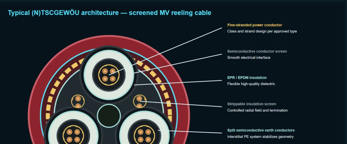
Modern (N)TSCGEWÖU products are commonly declared as based on DIN VDE 0250-813. The architecture combines flexible Class 5 or manufacturer-specific fine-stranded conductors, semiconductive conductor screens, EPR/EPDM insulation, strippable insulation screens, split semiconductive earth conductors, a torque-balanced lay, inner sheath, textile anti-torsion reinforcement and an abrasion-resistant outer sheath.
| Layer | Electrical function | Mechanical risk | Control |
|---|---|---|---|
| Power conductor | Carries load and fault current. | Strand fatigue, bird-caging, resistance increase. | Dynamic strand/lay design and resistance monitoring. |
| Conductor screen | Smooths the electric field at the conductor interface. | Cracking or separation under repeated bending. | Flexible compatible semiconductive rubber. |
| EPR/EPDM insulation | Primary dielectric. | Compression set, interface voids and thermal ageing. | Compound cure, concentricity, ageing and post-cycle PD. |
| Insulation screen | Maintains controlled radial field. | Fatigue and termination damage. | Controlled adhesion/strip force and smooth removal. |
| Split earth conductors | PE/fault path and symmetrical interstitial fill. | Movement, heating, discontinuity. | Semiconductive covering and verified continuity. |
| Sheath reinforcement | No electrical role unless specifically designed. | Late engagement, excessive stiffness or braid fracture. | Match reinforcement elongation to copper and termination. |
Medium-voltage electric-field control and partial discharge
In MV reeling cable, electrical ageing and mechanical fatigue interact. Curvature and radial pressure can disturb semiconductive interfaces, while strand impressions, contamination or screen separation can create local field enhancement. Routine voltage and partial-discharge tests therefore need to be considered again after representative mechanical cycling.
| Stage | Measurement | Engineering purpose | Acceptance basis |
|---|---|---|---|
| Raw materials | Volume resistivity, tensile/elongation and compatibility. | Control dielectric and semiconductive compound consistency. | Approved material specification. |
| Finished cable | Conductor resistance, voltage test, PD, screen/PE continuity. | Verify manufacture before dynamic use. | Applicable standard plus product specification. |
| After reeling test | Repeat resistance, voltage and PD; inspect interfaces. | Detect mechanical damage invisible at the sheath. | Pre-agreed project protocol. |
| After installation | Sheath/continuity, phase check and project-specific MV diagnostic test. | Detect handling, termination and reel-installation damage. | Commissioning procedure; do not automatically copy factory thresholds. |
A 2025 TFCrane R-(N)TSCGEWÖU datasheet publishes maximum 20 pC at 1.25 U0 for that product family. This is a useful factory-design reference, but it is not a universal field acceptance threshold for every (N)TSCGEWÖU cable.
Dynamic conductor and torque-balanced core lay
| Design variable | Desired effect | Failure if poorly coordinated | Evidence |
|---|---|---|---|
| Strand diameter | Reduce bending strain in each copper wire. | More interfaces and fretting if bunching is unstable. | Post-cycle strand count and resistance trend. |
| Lay length/direction | Allow strand migration without permanent bird-caging. | Corkscrew, core migration or local compression. | Torsion-under-tension and reverse-bend test. |
| Split earth geometry | Fill interstices and balance three-phase core layout. | Ovality, unequal pressure and PE movement. | Dimensional sections before/after cycling. |
| Separator friction | Permit controlled sliding while preventing adhesion. | Hard spots, wrinkles or conductor indentation. | Interface dissection and process control. |
| Sheath modulus | Hold the cable round without making it too stiff. | Flattening, buckling or excess bending force. | Crush, bending-force and recovery test. |
Tensile load, support elements and anti-torsion braid
Reel tension is generated by suspended cable weight, rolling/drag resistance, acceleration, reel torque, guide friction and emergency braking. A textile braid does not automatically carry the entire load: its braid angle, modulus, bond and elongation must engage before copper strain becomes damaging.
| Component | Failure mode | Required control |
|---|---|---|
| Cable conductor | Permanent elongation and strand breakage. | Stay within exact product tensile envelope. |
| Anti-torsion braid | Late load pickup, local rupture or sheath shear. | Coordinate braid strain with copper and termination. |
| Reel drive | Over-tension during start, stop or low-radius layer. | Torque curve, closed-loop control and overload protection. |
| Guide system | Friction spikes and bending concentration. | Correct alignment, surface finish and sheave diameter. |
| Cable grip/termination | Load transfers into electrical termination. | Dedicated strain relief outside the active bend zone. |
Each reel system creates a different cable problem
| System | Dominant stress | Cable priority | Machine control |
|---|---|---|---|
| Monospiral | High tensile load, stable single layer, centre-feed S-bend and possible torsion. | Reverse-bend endurance, roundness and tensile strength. | Controlled torque and correct guide position. |
| Cylindrical/level-wind | Traverse-guide bending, fleet angle and layer pressure. | Abrasion, crush resistance and torsion stability. | Precise level wind and layer tension. |
| Random-wind | Crossovers and variable effective radius. | Sheath toughness and deformation recovery. | Limit layers, crossover pressure and snagging. |
| Vertical/spreader | Large suspended mass and acceleration. | Early-engaging support and robust termination. | Lift profile, tension feedback and emergency stop. |
| Ground pickup | Abrasion, contamination and dragging before winding. | Tear/cut resistance and cleanable sheath. | Pickup guide, trench condition and cable alignment. |
Bending radius: use the real cable path, not one headline value
Bending strain rises approximately as cable diameter divided by bend diameter. The smallest radius may occur at the guide, S-bend or crossover—not at the drum core. The effective drum radius also grows by layer, changing both cable tension and heat dissipation.
| Mode | Why the value differs | Required input |
|---|---|---|
| Fixed installation | No repeated curvature, but termination transition still matters. | Route radius and installation temperature. |
| On operating drum | Repeated curvature plus radial layer pressure. | Core diameter, layers, torque and cycles. |
| Deflection pulley | Repeated concentrated bending and bearing friction. | Root diameter, groove profile and wrap angle. |
| Free movement | Cable can form uncontrolled loops and transient small radii. | Travel envelope and anti-kink control. |
| S-bend | Rapid curvature reversal accelerates conductor and screen fatigue. | Both diameters, spacing, change of plane and tension. |
Reeled ampacity is not the free-air current rating
| Input | Effect | Engineering action |
|---|---|---|
| Number of energized layers | Inner wraps lose cooling. | Calculate maximum wound and minimum paid-out states. |
| Load cycle | Crane peaks may be short but repetitive. | Use time-current data and cable thermal time constant. |
| Ambient/solar | Outdoor drums can start above air temperature. | Include solar gain and enclosure/drum heating. |
| Conductor AC loss | Resistance rises with temperature; harmonics add loss. | Use operating-temperature AC resistance and VFD spectrum. |
| Drum material | Changes heat flow and possible electromagnetic loss. | Model actual drum and phase geometry. |
| Terminations | Local contact resistance may dominate. | Temperature monitoring and torque-controlled connections. |
Design rule: DIN VDE 0298-4 ampacity is a starting framework. The actual reeled arrangement, duty cycle and number of energized layers require project-specific thermal verification.
VFD, EMC, protective earth and data integration
| Issue | Risk | Design response |
|---|---|---|
| VFD rise time | Reflections and repetitive peak voltage stress the insulation. | Provide drive voltage, cable length, dv/dt and filter arrangement. |
| Common-mode current | Bearing current, EMC emissions and PE heating. | Symmetrical phase/PE geometry and bonding design. |
| Split PE conductors | Incorrect termination can defeat symmetry. | Terminate all earth segments exactly as designed. |
| Control pairs | Inductive/capacitive coupling from power cores. | Individually screened balanced pairs and separation by design. |
| Optical fibre | Microbending, tensile transfer and termination damage. | Reeling-qualified loose/buffered element, strain control and OTDR limits. |
| Overall metallic screen | High cyclic strain and fatigue in dynamic cable. | Use only a screen architecture explicitly qualified for reel duty. |
Qualification testing: reproduce the complete stress spectrum
| Test | Replicated stress | Continuous monitoring | Post-test evidence |
|---|---|---|---|
| Reeling/unreeling | Drum curvature, tension, layer pressure and sheath contact. | Conductor/PE continuity, force, speed and temperature. | Resistance, visual inspection, diameter and dissection. |
| Reverse roller bending | Guide sheaves and S-bend curvature reversal. | Continuity and force. | Broken strands, core migration and screen condition. |
| Torsion under tension | Fleet angle, guide misalignment and direction change. | Torque, angle, force and continuity. | Corkscrew, layer displacement and electrical tests. |
| Crush/radial pressure | Lower drum layers and crossovers. | Load and deformation. | Recovery, dielectric integrity and sheath damage. |
| Abrasion/tear | Guides, grit, trench and flange contact. | Travel, force and counterface. | Wear depth and exposed reinforcement. |
| Thermal cycling energized | Loaded wound/paid-out duty. | Current and conductor/sheath temperature. | Ageing, resistance and interface inspection. |
| MV electrical after cycling | Latent dielectric/interface damage. | As required by protocol. | Voltage, PD and PE/screen continuity. |
| FO test | Micro/macro-bending and strain transfer. | Optical power where specified. | OTDR attenuation and event comparison. |
The cycle count, radius, tensile load, torsion angle, temperature and pass/fail limits must be agreed before testing. A rig capacity or catalogue maximum is not automatically the project test condition.
Published reference envelope—useful benchmarks, not universal guarantees
| Published product | Electrical values | Mechanical/thermal values | Correct use of the data |
|---|---|---|---|
| TFCrane NSHTÖU-J/O (2025) | U0/U 0.6/1 kV; Um 1.2 kV; AC test 3 kV. | Max conductor +90°C; short circuit +250°C; minimum ambient fixed −40°C, mobile −35°C. Catalogue suitability table shows up to 250 m/min with a product-scope footnote. | Benchmark only. Confirm the exact size, reel type and current revision. |
| TFCrane R-(N)TSCGEWÖU (2025) | 3.6/6, 6/10, 8.7/15 and 12/20 kV; AC tests 11, 17, 24 and 29 kV; PD 1.25U0/max 20 pC. | Catalogue: on-drum 12D; pulley 15D; moving free 10D; up to 180 m/min; 20 N/mm²; −25°C mobile; +90°C conductor. | Values belong to this TFKable R-series datasheet, not every (N)TSCGEWÖU. |
| PROTOLON (SMK) (N)TSCGEWÖU (2016 catalogue) | Published variants from 1.8/3 to 12/20 kV in the cited product section. | Catalogue product example: 20 N/mm², up to 30 N/mm² during acceleration, ±25°/m, S-change spacing 20D; consult above 240 m/min. | Manufacturer-specific high-dynamic envelope; do not combine with another supplier’s radius or PD table. |
| DIN VDE 0250-814 / -813 | Product-standard routes for NSHTÖU and trailing cable. | The standards define controlled constructions/tests; the project still needs machine-specific dynamic limits. | Purchase the applicable standard and verify edition/compliance. |
No parameter mixing: a procurement specification must not take speed from one manufacturer, bend radius from a second, tensile load from a third and then demand that the hybrid set is “standard.” It may define a new project requirement, but it must be qualified as such.
Selection matrix for port, bulk-handling and mining equipment
| Machine | Dominant duty | Preferred starting family | Critical project inputs |
|---|---|---|---|
| Ship-to-shore crane travel | High-speed horizontal reel, VFD, salt/UV, S-bend. | High-dynamic (N)SHTÖU at LV or (N)TSCGEWÖU at MV. | Speed, acceleration, reel/guide layout, VFD waveform, layers and FO. |
| RTG/RMG electrification | Frequent travel, outdoor heat, compact guides. | Reeling-qualified LV/MV multicore design; voltage decides family. | Duty cycle, cable length, e-house interface and reel automation. |
| Stacker/reclaimer | Long payout, dust, abrasion, level/random winding. | NTS/(N)TSCGEWÖU heavy-duty route. | Trench, vertical component, drag, drum layers and travel cycles. |
| Ship loader/unloader | Multiple direction changes and marine contamination. | High-dynamic (N)TSCGEWÖU where MV power is required. | S-bends, guide planes, salt/oil exposure, terminations. |
| Bucket/spreader vertical reel | High hanging mass and rapid lifting acceleration. | Dedicated support-element/vertical-reeling design. | Suspended length, acceleration, tensile load and grip system. |
| Open-cast excavator | Severe trailing/reeling, dirt, impact and torsion. | NTS or (N)TSCGEWÖU mining/heavy mobile type. | Ground route, reel, voltage, monitoring, repair strategy. |
| Tunnel boring machine | MV supply, confined routing, moisture and high reliability. | TBM-specific (N)TSCGEWÖU derivative. | Voltage, reel/gantry route, fire strategy, joints and monitoring. |
Feichun Cable engineering and certification boundary
Engineered for maximum safety in demanding environments, our cable systems comply with global standards including ATEX, IECEx, VDE, CE, UKCA, EAC, and the Russian Fire Safety Certificate. They are the trusted choice for heavy-duty mining equipment, ship-to-shore cranes, RTG/RMG cranes, and conveyor systems where high reliability is non-negotiable.
Certificate applicability must be verified against the exact cable type, voltage, construction, manufacturing site, certificate number, validity period and intended hazardous-area equipment. A “based on DIN VDE” construction does not automatically carry a VDE product approval, and a cable certificate does not certify the complete reel or machine.
Installation and commissioning rules that prevent early failure
| Step | Required practice | Failure prevented |
|---|---|---|
| Transfer to operating drum | Maintain the manufacturer’s recommended winding sense; avoid uncontrolled de-kinking. | Permanent twist and core-lay destabilization. |
| Guide inspection | Measure root diameters, alignment, groove shape and all contact surfaces. | Localized bending, cuts and friction spikes. |
| Fleet angle | Check throughout full travel and every drum layer. | Torsion and flange abrasion. |
| Strain relief | Transfer mechanical load before electrical terminations. | Conductor pull-out and stress-control movement. |
| MV preparation | Use trained jointers, controlled stripping and compatible accessories. | Semiconductive residues, insulation scoring and PD. |
| Initial run | Operate at reduced speed while recording tension, tracking and temperature. | Undetected over-torque, rubbing or reverse winding. |
| Baseline tests | Record resistance/continuity, sheath, MV/PD or FO data as applicable. | No reference for future condition assessment. |
Failure symptoms and engineering diagnosis
| Symptom | Likely mechanism | Evidence to collect | Corrective action |
|---|---|---|---|
| Corkscrew after payout | Forced twist, wrong winding sense or unbalanced lay. | Photos by travel position, guide rotation and residual twist. | Correct route/install; review torque-balanced construction. |
| Break at drum tangent | Small core diameter or excessive torque. | Actual OD, core root radius, dynamic tension and cycles. | Increase radius, reduce tension or redesign cable. |
| MV PD increase | Interface damage, termination defect or contamination. | PD pattern/location, test history and mechanical event log. | Locate defect; inspect termination/cable and retest. |
| Split PE discontinuity | Earth-element fatigue or termination load transfer. | Individual PE resistance and dissection. | Repair/replace; correct termination and dynamic design. |
| Lower-layer flattening | Excess radial pressure or crossover. | Layer pattern, tension and diameter recovery. | Improve level wind, limit layers or stronger geometry. |
| Outer sheath spiral wear | Fleet angle or guide/flange contact. | Wear map, alignment and contact-surface inspection. | Correct guide geometry and smooth hardware. |
| Hot wound reel | Free-air ampacity applied to trapped layers. | Layer count, load profile and thermal imaging. | Derate, pay out more cable or redesign the thermal duty. |
| FO attenuation varies with travel | Microbending or strain transfer. | Live optical power and OTDR at defined positions. | Correct route/support or use reeling-qualified FO element. |
Frequently asked questions and project input checklist
Is NSHTÖU always suitable for high-speed reels?
No. Standard identity does not establish every speed, tension or cycle. Use the exact product envelope or a qualified high-dynamic derivative.
Does (N) mean fully VDE standardized?
No. Parenthesized N commonly signals a design based on a DIN VDE construction. Request the compliance/deviation matrix and certificate scope.
Can NTS be used as the complete model?
No. The suffix, voltage, earth/screen architecture and mechanical duty are essential parts of the specification.
Why split the earth conductor?
Split earth elements can fill interstices, improve phase symmetry and stabilize geometry while providing the PE path.
Is 20 N/mm² universal?
No. It is published for specific product families. The allowable load depends on construction, temperature, support system and termination.
Can a 12D drum radius be used for every MV cable?
No. It is a specific published example. The exact cable datasheet and operating mode control.
Should PD be measured after dynamic testing?
For MV cable, repeating PD and voltage tests after representative cycling is strong evidence that interfaces remained intact.
Can the cable be repaired in the active bend zone?
Only under an approved repair procedure. A local stiff repair can move fatigue to its edge and compromise field control.
Technical sources and argument support
- VDE VERLAG — DIN VDE 0250-814:1985-02: official valid-standard page for the NSHTÖU rubber-insulated flexible cable.
- DIN Media — DIN VDE 0250-813:1985-05: current standard page identifying the Part 813 trailing-cable scope.
- TFCrane catalogue, 2025: NSHTÖU and R-(N)TSCGEWÖU structures, voltage classes, published mechanical envelopes, dimensional tables and application boundaries; see product sections beginning on catalogue pages 18 and 32.
- TFCrane R-(N)TSCGEWÖU datasheet, 2025: source for the clearly bounded MV voltage, PD, radius, speed, tensile and temperature examples summarized above.
- Prysmian Crane Cables technical catalogue: NSHTÖU, NTS and PROTOLON (SMK) (N)TSCGEWÖU background; see product pages 92–99 and technical appendix pages 122–140.
- IEC 60228:2023: conductor classes, cross-sectional areas and resistance requirements; conductor class alone does not establish reeling life.
- DIN VDE 0298-3:2006-06: use guidance for cables and flexible cords in power installations.
- DIN VDE 0298-4:2023-06: current-carrying-capacity framework; wound-layer thermal conditions still require project assessment.
- IEC 60811-404:2012 and IEC 60811-403:2012: oil-immersion and ozone-resistance material test methods.
- IEC 60332-1-2:2025: vertical flame-propagation test for a single cable; this test does not prove dynamic reeling endurance.
Standards and manufacturer catalogues are copyrighted; this article summarizes verified scope and engineering principles without reproducing controlled standards. Values identified as published references remain the property and responsibility of their source product. No Feichun speed, bending radius, cycle life, tensile rating, OD, mass, PD limit or current rating is declared without an exact approved Feichun cable design.


