
Complete technical guide for identifying, understanding, and working with pilot cores in Type 3S earth-continuity-monitored mining cables. Pilot core versus earth core distinction, field identification techniques, circuit architecture, monitoring principles per AS/NZS 2081, and practical installation procedures for underground mechanized mining equipment feeder systems.
在Type 3S接地连续性监控矿用电缆中识别、理解和使用导引线的完整技术指南。导引线与接地线的区别、现场识别技术、电路架构、根据AS/NZS 2081的监控原理,以及地下机械化采矿设备馈电系统的实际安装程序。
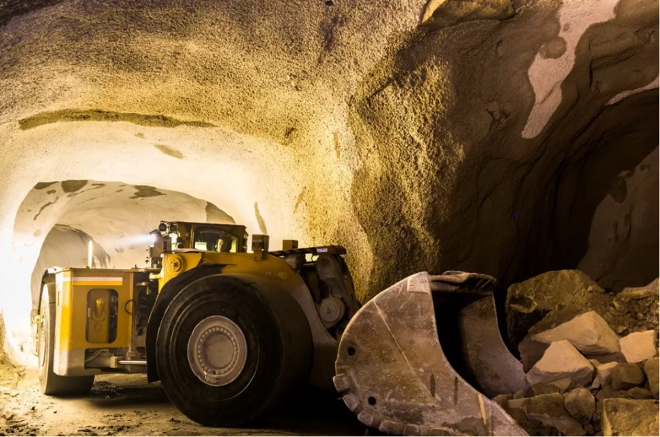
Earth Fault Monitoring: Identifying Pilot Cores in Type 3S 6.6kV 3x150mm² Feeder Cables
Complete technical guide for identifying, understanding, and working with pilot cores in Type 3S earth-continuity-monitored mining cables. Pilot core versus earth core distinction, field identification techniques, circuit architecture, monitoring principles per AS/NZS 2081, and practical installation procedures for underground mechanized mining equipment feeder systems.
在Type 3S接地连续性监控矿用电缆中识别、理解和使用导引线的完整技术指南。导引线与接地线的区别、现场识别技术、电路架构、根据AS/NZS 2081的监控原理,以及地下机械化采矿设备馈电系统的实际安装程序。
1. Direct Answer: What Is a Pilot Core and Why Does It Matter?
A pilot core is a small-diameter, individually insulated conductor that runs the full length of a Type 3S mining cable alongside the power conductors and earth cores. Its purpose is to carry a low-voltage supervisory signal from the substation to the remote equipment and back, allowing a monitoring relay at the substation to continuously verify that the cable’s earth return path (the path through which fault currents flow to ground) remains intact and unbroken. In a Type 3S 6.6kV 3x150mm² cable, the pilot core is typically 10–25 mm² in cross-sectional area (much smaller than the 150 mm² power conductors), has its own color-coded insulation to distinguish it from the two earth cores, and is the critical difference that transforms a cable from simple power delivery (Type 2S) into a safety-monitored system (Type 3S). For equipment like continuous miners, pump stations, or large longwall systems that operate far from direct visual supervision, the pilot core provides the electrical equivalent of a “safety tether”—if that tether breaks, the system knows immediately and can shut down before a dangerous fault condition develops.
导引线是一根小直径、单独绝缘的导体,贯穿Type 3S矿用电缆的全长,与动力导体和接地线并行。其目的是从变电站携带低压监控信号到远程设备并返回,允许变电站的监控继电器持续验证电缆的接地回路路径(故障电流流向地的路径)保持完整且未中断。在Type 3S 6.6kV 3×150mm²电缆中,导引线通常截面积为10–25 mm²(远小于150 mm²的动力导体),有自己的彩色绝缘以区别于两条接地线,是将电缆从简单的电力输送(Type 2S)转变为安全监控系统(Type 3S)的关键区别。
To understand why this matters, consider what happens in an underground mine when a heavy piece of equipment, such as a mobile crusher or pump unit, is powered by cable that runs along the mine floor for several hundred meters. The cable is subject to extraordinary abuse: rolling equipment may pass over it, hydraulic fluid may leak on it, rocks may fall on it, and the cable may be bunched with other cables or jammed into confined spaces. During all of this, the cable’s earth return path must remain intact. If the cable is damaged in a way that breaks the earth connection (without simultaneously breaking the power conductors), the equipment continues operating normally—the operators have no warning that danger lurks. But if another fault event occurs (perhaps a second piece of damage affecting a different phase), the system is now defenseless against the resulting arc and explosion. The pilot core changes this scenario. By continuously testing whether the earth path is open or closed, the monitoring relay detects the first sign of cable deterioration and can cut power before the cascade of failures leads to disaster.
2. Understanding Earth Continuity Monitoring: Why Type 3S Exists
Before we examine the specific role of the pilot core, it helps to step back and understand the broader philosophy behind earth continuity monitoring (ECM) and why regulatory authorities in Australia require it for certain mining applications. This context will make the pilot core’s function clearer.
In underground coal mining, equipment protection systems are designed around the concept of defense-in-depth: multiple redundant safety measures ensure that if one fails, others remain to protect personnel and assets. One critical level of this defense involves the cable itself. The cable’s design—particularly its individual screening and earth connections—is engineered to prevent fault currents from flowing through the surrounding atmosphere (where they could ignite methane) and instead to guide them safely to ground. But here is the challenge: a cable buried underground or running along the mine floor cannot be visually inspected on a daily basis. Its condition deteriorates gradually, or suddenly due to mechanical damage, and the operators may have no way of knowing.
This is where earth continuity monitoring becomes essential. The principle is simple but powerful: from the substation, send a low-voltage signal down a dedicated conductor (the pilot core) that tests the integrity of the earth connection. If the earth path is intact, the signal returns to the substation, and the relay receives confirmation that all is well. If the earth path is broken—because the cable was damaged, a joint was improperly made, or a connection corroded—the signal does not return, and the relay immediately detects the anomaly. The relay can then be set to cut power to the affected circuit before fault conditions escalate.
This monitoring is not passive. It is a continuous, active test that occurs at regular intervals (often every few seconds). It is designed by mining engineers to catch problems before they become catastrophes. For this to work, the pilot core must be physically distinct from the earth cores, properly terminated at both the substation and the remote equipment, and properly understood by installation personnel who will be handling the cable in the field. Many field failures stem from workers who are unfamiliar with the distinction between the pilot core and earth cores, and who accidentally damage one or terminate it incorrectly.
Earth continuity monitoring became mandatory in Australian mining regulations following a series of incidents where cable damage went undetected until a second fault event triggered a mine explosion. The regulation requires that for equipment operating remotely or where continuous visual inspection is impractical, the cable system must incorporate active monitoring of the earth path. Type 3S cable, with its dedicated pilot core, was the industry’s answer to this regulatory requirement. Type 2S cables, lacking the pilot core, cannot support earth continuity monitoring and are therefore prohibited for certain high-risk applications like large mechanized equipment in deep underground mines.
3. Type 3S Architecture: How It Differs Fundamentally from Type 2S
To properly identify a pilot core, you must first understand how Type 3S cable is constructed and what makes it structurally different from the more common Type 2S cable. Both are individually screened cables designed for underground mining, but Type 3S adds an extra conductor to support the monitoring function.
Imagine looking at a cross-section of a cable (slicing the cable perpendicular to its length and examining the face). At the center are three large conductors, each several millimeters in diameter, that carry the three-phase power. These are the power cores, and they are where the electrical energy flows to the equipment. In Type 2S, surrounding these three power cores are three additional smaller conductors positioned in the “interstices”—the natural gaps between the three larger cores. These three smaller conductors are the earth cores, and they serve multiple purposes: they carry fault currents from the cable back to ground, they balance the electric field symmetrically around the cable, and they can be bonded to the equipment’s frame to ensure electrical continuity.
In Type 3S, the internal arrangement is similar, except for one crucial detail: instead of three earth cores, there are only two earth cores and one additional conductor that serves a completely different function. This extra conductor is the pilot core. It is significantly smaller than either the power cores or the earth cores (typically 16–25 mm² in cross-section, compared to 150 mm² for the power cores and 50–70 mm² for the earth cores). It has its own layer of insulation, and that insulation is a distinct color (often light blue, red, or another color depending on the manufacturer) to distinguish it visually from the other conductors. The pilot core runs the full length of the cable and is brought out at both the substation end and the remote equipment end, where it is connected to a monitoring relay circuit.
This seemingly small change—replacing one earth core with one pilot core—fundamentally changes the cable’s capabilities. A Type 2S cable is a simple power delivery device. A Type 3S cable is a power delivery device plus a continuous health monitoring system. For equipment operating in remote locations where cables cannot be regularly inspected, this health monitoring function can be the difference between safe and dangerous operation.
4. The Pilot Core’s Role in the Monitoring Circuit
Now that we understand the basic structure, let us examine precisely how the pilot core functions in the monitoring circuit and what role it plays in detecting cable faults. This is where the elegance of the Type 3S design becomes apparent.
At the substation, a dedicated earth continuity monitoring relay (sometimes called an earth fault relay or ECM relay) is connected in a simple circuit. One terminal of the relay connects to the pilot core at the substation. Another terminal of the relay connects to the equipment’s frame (the structural metal of the substation enclosure or equipment). The relay is designed to send a low voltage (typically 24 volts DC, a safe level far below the 6.6 kV main power voltage) down the pilot core. This low voltage is provided by a small power supply within the relay itself.
At the remote equipment end (perhaps a continuous miner or pump station hundreds of meters away in the mine), the pilot core is terminated and connected to a bonding lug or stud that is bolted to the equipment’s metal frame. The two earth cores are also brought out and connected to the same bonding point. So at the remote equipment end, there is a connection point where the pilot core joins with the earth cores, and where this combined point bonds to the equipment frame.
Now let us trace the circuit: the relay at the substation sends current down the pilot core. That current travels through the copper conductor of the pilot core, from the substation toward the remote equipment. When it reaches the remote equipment, it encounters the bonding point where the pilot core meets the earth cores. The current has now completed a path from the pilot core to the earth cores. From the earth cores, the return path is back through the SWA armor (which is bonded to the earth cores) or through the plant frame bonding conductors to the substation earth. The current returns to the relay, completing the loop. The relay detects this return current and registers “all is well—the earth path is intact.”
But what if the cable is damaged? Suppose a sharp rock punctures the cable and severs the armor at one location, or a contractor’s excavator drives a bucket through the cable, tearing it open. If the damage is severe, both the pilot core and the earth cores might be severed. But if the damage is more localized—perhaps affecting one part of the armor but not the central pilot core and earth cores—the pilot core might remain intact while one of the earth cores is broken. In this scenario, the monitoring relay still sends current down the pilot core, but now that current cannot return properly. Instead of the expected return current flowing back through the intact earth core, there is an open circuit. The relay detects this absence of return current and immediately signals an alarm, triggering the circuit breaker to open. The equipment loses power before a cascading fault can develop.
This is why the distinction between the pilot core and the earth cores is so critical. If a field technician were to confuse them during cable installation and accidentally cut or damage what they thought was an earth core but was actually the pilot core, the entire monitoring system would be disabled. The next fault event might go undetected until it is too late.
5. Physical Identification: How to Recognize a Pilot Core in the Cable Cross-Section
When a Type 3S cable arrives at a mine site and must be installed or terminated, technicians need to be able to identify the pilot core accurately. This is not difficult once you know what to look for, but it requires understanding a few physical characteristics. The best time to practice this identification is when the cable is first being prepared for installation—before any field work begins.
To visually identify the pilot core, you must expose the cable’s internal conductors. This typically involves cutting away the outer PVC sheath and carefully removing the SWA armor over a length of about 50–100 mm. Once the armor is removed, you will see the inner PVC sheath underneath. Carefully removing this inner sheath (again, using a sharp knife or cable stripping tool, being careful not to nick the internal conductors) reveals the bundle of three power cores plus the two earth cores and one pilot core.
At this point, looking at the cross-section, you will see five conductors in the interstices (the spaces between the three large power cores). Three of these are large, with cross-sections of approximately 50–70 mm² each—these are the earth cores. Two of these are much smaller—one will be approximately 16–25 mm² in cross-section, and the other will be even smaller or sometimes absent. The one that is distinctly smaller and has a complete layer of insulation in a contrasting color is the pilot core.
How to distinguish visually: First, consider size. The pilot core is noticeably smaller. If you see five conductors in the interstices and four of them are roughly the same size while one is significantly smaller, that smaller one is likely the pilot core. Second, look at insulation color. The earth cores may be bare copper, or they may have only a thin gray or black semiconductive coating. The pilot core, in contrast, has a full-thickness layer of colored insulation—perhaps light blue, red, yellow, green, or another color depending on the manufacturer. This colored insulation makes it stand out visually. If you are unsure, do not guess. Consult the cable’s technical documentation (the specification sheet that should accompany the cable when it is delivered), or contact Feichun’s technical support team before proceeding with installation.
A useful field test is to measure the resistance of each small conductor using a multimeter. The two earth cores, being thicker and made of pure copper, will have very low DC resistance (a few milliohms per meter). The pilot core, being thinner, will have higher resistance (perhaps 10–20 times higher). This resistance measurement is not a definitive identification (it requires access to a multimeter and some electrical knowledge), but it can serve as a verification if you are unsure about visual identification.
6. The Three-Conductor Return Path: Understanding the Monitoring Loop
To fully appreciate why the pilot core is essential, and why it must be kept distinct from the earth cores, it helps to understand the complete return path that current follows during normal monitoring operation and during a fault condition.
During normal operation, the monitoring relay at the substation sends a low-voltage signal down the pilot core. This pilot core signal must return to the relay to complete the circuit. But how? The pilot core, while insulated and dedicated, is not part of the main equipment bonding system in the same way the earth cores are. So the return path must involve the earth cores. Here is the typical connection at the remote equipment end: the pilot core is brought out of the cable and is connected, typically via a dedicated terminal block or bonding lug, to the equipment’s grounding system. That grounding system is also bonded to the earth cores and the SWA armor. So the return path is: pilot core (at remote end) → bonding lug → equipment frame → bonding to earth cores → earth cores (back through the cable) → SWA armor bonding → substation ground.
If any part of this path becomes open—if the pilot core is severed, if the bonding lug is improperly installed, if the earth cores are broken, or if the SWA armor connection is corroded—the monitoring relay will not receive the expected return signal. This lack of return signal is what triggers the alarm. In this way, the Type 3S system can detect not just pilot core breakage, but any break in the earth return path, whether it is in the pilot core itself, the earth cores, or the bonding connections.
7. AS/NZS 2081 Compliance: What the Standard Requires
The requirements for earth continuity monitoring in Australian underground coal mines are specified in AS/NZS 2081, the standard that governs electrical installations in mines and quarries. While a full discussion of this standard is beyond the scope of this article, understanding a few key requirements will help explain why pilot cores are implemented the way they are.
AS/NZS 2081 requires that for equipment operating remotely or in locations where cable inspection is impractical, an earth continuity monitoring system must be in place. This system must continuously monitor the integrity of the earth path at least once every few seconds (the exact interval depends on the specific application and risk assessment). The monitoring signal must be isolated from the main power circuit—it must use a separate, low-voltage circuit dedicated to monitoring alone. The monitoring relay must be capable of detecting a break in the earth path and must be configured to cut power to the affected circuit when a break is detected.
Type 3S cables with pilot cores satisfy these requirements elegantly. The pilot core is the isolated, low-voltage signal conductor. The monitoring relay tests it continuously. If it becomes open, the relay detects it and triggers a fault clearance. In this way, Type 3S cables enable mines to comply with AS/NZS 2081 requirements for remote equipment monitoring.
8. Cable Stripping and Termination: Protecting the Pilot Core
When a Type 3S cable is prepared for installation at a mine site, it must be carefully stripped and terminated. The pilot core is vulnerable during this process and must be handled with care. Understanding the correct procedures prevents accidental damage.
The general stripping procedure for Type 3S is similar to that for other armored cables. The outer PVC sheath is removed to expose the SWA armor. The armor is then carefully removed by unwinding or cutting away the helically wound steel wires. This exposes the inner PVC sheath beneath the armor. The inner sheath is carefully stripped away to expose the individual conductors: the three power cores, the two earth cores, and the pilot core.
At this stage, extreme care must be taken. The pilot core, being smaller and having full insulation, is somewhat fragile. A slip of the stripping tool can nick the insulation and create a weak point that could later break under mechanical stress during installation. The pilot core must be stripped only the exact length required for termination (typically 20–30 mm) to avoid accidental damage to insulation that will not be used.
When terminating, the pilot core is brought out separately from the earth cores. It is connected to a dedicated terminal or lug within the monitoring relay terminal block. This isolation ensures that the pilot core circuit remains independent from the main equipment grounding. If the pilot core were accidentally bonded to the same lug as the earth cores before reaching the relay, the monitoring circuit would be bypassed and the system would not function.
After termination but before the cable is energized, a simple test should be performed to verify that the pilot core is properly connected and not damaged. Using a multimeter set to resistance mode, measure the DC resistance from the pilot core terminal at the substation to the pilot core at the remote equipment end. The measurement should show a low but measurable resistance (consistent with copper at the measured distance). If the resistance is infinite (open circuit), the pilot core is broken and must not be put into service. If the resistance is unexpectedly low or shows a pattern of variation, there may be insulation damage. Do not proceed until the cause is identified and resolved.
9. Field Installation Scenarios: Where Pilot Core Identification Matters Most
To bring this technical discussion into practical context, consider several real-world installation scenarios common in Australian underground coal mines. In each scenario, correct identification and handling of the pilot core is essential to the success of the installation.
Scenario 1: Initial Equipment Installation A new pump station is being established 300 meters into a gateroad (development heading) leading to the main mining area. Power must be supplied from the pit substation via a Type 3S 6.6kV feeder cable approximately 400 meters long. The cable is delivered on a heavy reel and must be manually laid out along the floor of the gateroad, brought into the pump station enclosure, and terminated to the substation distribution board. When the cable arrives at the installation crew’s work area, a technician must prepare the cable end for termination. That technician must be able to identify the pilot core, strip it correctly without damaging its insulation, and connect it to the monitoring relay terminal. If the technician is unfamiliar with pilot cores and confuses it with an earth core, accidentally cutting the pilot core insulation, the installation will be delayed while the damage is investigated and possibly repaired.
Scenario 2: Cable Splicing in the Field A cable originally specified as a single 500-meter run must be shortened during mine layout changes. The cable is to be cut at 350 meters and spliced. After cutting, the field technician must splice the pilot core with a field termination kit designed for earth continuity monitored cables. If the technician does not understand that the pilot core is separate and must be spliced differently from the earth cores (using a dedicated, insulated splice kit rather than a simple mechanical connection), the splice may be made incorrectly. This would either degrade the monitoring function or potentially cause a short circuit between the pilot core and earth cores.
Scenario 3: Cable Damage Assessment A cable has been damaged by mobile equipment that ran over it. The equipment operator reports to the supervisor, and the cable is brought to the substation for inspection. The electrical engineer must determine whether the cable can be repaired or must be replaced. To make this assessment, the engineer must cut away the damaged section and examine the internal conductors. Can the engineer identify which conductor is damaged? If the pilot core is damaged but the earth cores are intact, the cable can potentially be spliced or repaired in a way that restores power but recognizes the monitoring function is compromised. If an earth core is damaged but the pilot core is intact, a different repair approach might be taken. If the engineer cannot distinguish between the pilot core and earth cores, the assessment cannot be made accurately.
10. Common Mistakes: What Goes Wrong When Pilot Cores Are Misidentified
Drawing on field experience from mines across Australia, several common mistakes have been observed when technicians are not properly trained in pilot core identification. Understanding these mistakes helps illustrate why proper identification is so important.
Mistake 1: Cutting the Pilot Core During Stripping A technician removes the inner PVC sheath from a Type 3S cable in preparation for termination. Because the pilot core is smaller and has colored insulation, it stands out visually and may be mistaken for a foreign object or a stray piece of material. The technician attempts to remove it, inadvertently cutting through the insulation with a knife. Later, when the cable is energized, the monitoring relay fails to detect proper return signal, and a false alarm triggers repeatedly.
Mistake 2: Bonding the Pilot Core to the Same Lug as Earth Cores A technician correctly identifies the pilot core but does not understand why it must be bonded separately. Thinking to simplify the work, the technician connects the pilot core, earth cores, and armor to a single large bonding lug. While this might provide adequate grounding, it bypasses the pilot core’s isolation. The monitoring circuit no longer functions, and the cable is no longer truly Type 3S—it has been converted to the equivalent of Type 2S.
Mistake 3: Damaging Pilot Core Insulation During Field Splicing When a field splice is required, a technician uses a standard mechanical splice intended for large conductors. The pilot core, being thinner, is difficult to secure in this large splice, and the insulation is crushed or nicked. Water later seeps into the damaged insulation during wet mine conditions, creating a short circuit that disables the monitoring relay.
Mistake 4: Failing to Test the Pilot Core After Installation After cable termination, no test is performed to verify that the pilot core is intact and properly connected. The cable is energized with the pilot core damaged or disconnected. The monitoring system is non-functional, and if a fault occurs in the earth path weeks later, the monitoring relay cannot detect it because the pilot core circuit has been inoperative all along.
11. Technical Specification: Type 3S 6.6kV 3x150mm² Complete Data
To facilitate proper specification and identification of Type 3S cables for your mining application, the following table provides comprehensive technical data for a 3x150mm² Type 3S cable at 6.6kV, one of the most commonly used sizes for underground mechanized mining equipment feeder systems.
| Parameter | Specification | Engineering Notes |
|---|---|---|
| Power Cores | 3 × 150 mm² (stranded copper, Class 2) | Main electrical conductors carrying 6.6kV three-phase power |
| Earth Cores | 2 × 70 mm² (typical, bare or semi-conducting) | Return path for earth faults; bonded to armor and equipment frame |
| Pilot Core | 1 × 16 mm² (insulated, colored layer, Class 2 stranded) | Dedicated conductor for ECM (Earth Continuity Monitoring) signal; must be kept separate from earth cores |
| Insulation | XLPE (cross-linked polyethylene), 2.5 mm thickness per power core | 90°C rated conductor temperature; higher temperature handling during short circuit |
| Individual Screening | Copper tape or copper wire braid per power core | Ensures symmetrical electric field and reliable phase-to-earth fault detection |
| Armoring (SWA) | Galvanized steel wire (3.15–3.3 mm diameter typical) | Mechanical protection; serves as secondary earth return path |
| Outer Sheath | Flame-retardant PVC (1.0 mm thickness) | Environmental protection; meets AS/NZS 1972 flame spread requirements |
| Outer Diameter | 68.0–74.0 mm (typical 71 mm) | Affects cable tray sizing, conduit selection, and equipment entry gland specification |
| Copper Weight | Approximately 5,800 kg/km | Includes power conductors, screening, earth cores, and pilot core |
| Total Weight | Approximately 11,000–11,500 kg/km | Heavy-duty field installation requires mechanical cable handling equipment |
| Current Capacity | Approximately 335 A (air installation, 40°C ambient) | Subject to AS/NZS 3008 derating for underground installation and thermal environment |
| Minimum Bend Radius | 15 × outer diameter (approximately 1,065 mm) | Fixed installation; cable should not be repeatedly flexed due to SWA armor design |
| Short Circuit Rating | Phase conductor ~21.4 kA @ 1 sec; earth screen ~7.1 kA @ 0.1 sec | Validates cable’s thermal withstand in fault conditions; ensures protection system coordination |
12. Conclusion: The Pilot Core as Lifeline in Underground Mining
The pilot core in a Type 3S cable represents a fundamental shift in how underground mining systems approach electrical safety. Rather than relying solely on cable design to prevent faults, Type 3S cables add an active monitoring layer that continuously verifies the cable’s integrity. For equipment operating remotely in underground mines—continuous miners hundreds of meters from direct supervision, pump stations in isolated locations, or longwall systems that cannot be visually inspected daily—this continuous monitoring transforms cable failure from an invisible hazard into a detected, managed risk.
The pilot core itself is a small conductor, easily overlooked by workers unfamiliar with its purpose. But its simplicity belies its importance. A pilot core that is properly identified, correctly terminated, and continuously monitored can be the difference between safe, controlled operation and a catastrophic fault event. When a cable is damaged—and in underground mining, damage is not a question of if, but when—the pilot core’s ability to detect that damage and trigger a controlled shutdown represents the final layer of defense between personnel and danger.
If you are planning to install Type 3S feeder cables for underground mining equipment, ensure that every member of your installation team understands the pilot core’s function, can identify it visually in the cable cross-section, and understands the proper termination procedures. Feichun’s technical team is available to provide training, documentation, and field support to ensure that your Type 3S cable installation achieves its full safety potential. The cable’s technology is only valuable if it is understood and correctly implemented in the field.
References & Sources
- AS/NZS 1972:2012, “Fixed electric cables—General purpose cables for underground mining,” Standards New Zealand and Standards Australia.
- AS/NZS 2081:2016, “Electrical safety in mining,” Standards New Zealand and Standards Australia.
- Feichun Special Cable Type 3S Cable Installation and Commissioning Guide, Technical Documentation, 2024.
- AS/NZS 3008.1.1:2017, “Electrical installations—Selection of cables—General requirements,” Standards New Zealand and Standards Australia.
- WorkSafe Victoria, “Electrical Safety in Mining—Underground Coal Mines,” Industry Code of Practice, 2023.


