
Comprehensive Technical Guide to Outdoor Loose Tube Dielectric Fiber Optic Cables for Wind Farm Telecommunication and SCADA Systems — VDE Equivalent: A-DQ(ZN)B2Y
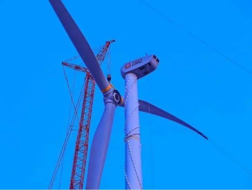
What is Z-XOTKtsdDb Glass Yarn Reinforced Fiber Optic Cable?
Comprehensive Technical Guide to Outdoor Loose Tube Dielectric Fiber Optic Cables for Wind Farm Telecommunication and SCADA Systems — VDE Equivalent: A-DQ(ZN)B2Y
1. Introduction to Z-XOTKtsdDb Fiber Optic Cable Technology
The Z-XOTKtsdDb represents a specialized category of outdoor fiber optic cables engineered for telecommunication infrastructure in wind energy installations. This fully dielectric, glass yarn reinforced loose tube cable provides the backbone for Supervisory Control and Data Acquisition (SCADA) systems that monitor and control wind turbine operations across entire wind farm networks.
Why Fiber Optics in Wind Farms? All-dielectric fiber optic cables offer the critical advantage of reducing ground potential to help protect sensitive control equipment in the event of lightning strikes. Complex wind farms are commonly operated through fiber optic cables and switches to connect servers to turbines for monitoring and control of wind power plants.
Reference: Fiber Optic Cables for Offshore Wind Applications — Crane Cable
The cable designation Z-XOTKtsdDb follows Polish telecommunications naming conventions while maintaining functional equivalence to the German VDE standard A-DQ(ZN)B2Y. Both designations describe an outdoor, loose tube, dielectric construction with glass yarn reinforcement for rodent protection — essential characteristics for wind farm installations where cables must withstand harsh environmental conditions and potential wildlife damage.
2. Cable Designation Analysis
2.1 Z-XOTKtsdDb Designation Breakdown
2.2 VDE Equivalent: A-DQ(ZN)B2Y Designation
This metal-free optical fiber outdoor cable is suitable for installations directly into the earth or in conduits in telecommunications and data processing systems. The stranded design is available up to 144 fibers, with multifunctional reinforced glass roving braiding serving as both a non-metallic stress-relieving element and armor for rodent protection.
Reference: A-DQ(ZN)B2Y Light Dielectric Outdoor Cable — AllKabel Technical Specifications
3. Optical Fiber Types
The Z-XOTKtsdDb cable supports multiple optical fiber configurations to meet diverse network requirements, from short-distance campus connections to long-haul wind farm interconnections.
9/125 μm
Shifted Singlemode
50/125 μm
62.5/125 μm
| Parameter | Singlemode (J) G.652D | NZD Singlemode (Jn) G.655 | Multimode (G/50) OM2/OM3 | Multimode (G/62.5) OM1 |
|---|---|---|---|---|
| Core Diameter | 9 μm | 9 μm | 50 μm | 62.5 μm |
| Cladding Diameter | 125 μm | 125 μm | 125 μm | 125 μm |
| Mode Field Diameter | 8.6–9.5 μm @1310nm | 8.0–11.0 μm @1550nm | N/A | N/A |
| Attenuation @1310nm | ≤0.35 dB/km | — | — | — |
| Attenuation @1550nm | ≤0.22 dB/km | ≤0.22 dB/km | — | — |
| Attenuation @850nm | — | — | ≤2.5 dB/km | ≤3.0 dB/km |
| Bandwidth @850nm | — | — | ≥500 MHz·km | ≥200 MHz·km |
| Max Distance (1G) | 10+ km | 40+ km | 550 m | 275 m |
| Typical Application | Long-haul, WAN | DWDM systems | Data centers, LAN | Legacy systems |
4. Cable Construction
4.1 Layer-by-Layer Structure
4.2 Construction Materials Summary
Core Components
Central Member: Dielectric FRP rod
Loose Tube Material: PBT (Polybutylene Terephthalate)
Tube Fill: Thixotropic gel (water-blocking)
Filler Material: Solid polyethylene
Core Configurations: 6, 8, or 12 elements
Protection Systems
Water Blocking: Dry sealing with hot melt adhesive
Reinforcement: E-glass yarn layer
Rodent Protection: Glass yarn armoring
Outer Jacket: Black HDPE
Identification: Ink jet printed markings
The loose tube cable construction isolates the optical fibers from installation and environmental stresses, providing stable and highly reliable transmission parameters. Fibers are color-coded following IEC 60304 or TIA/EIA-598 standards for quick and easy identification during splicing and termination operations.
Reference: A-DQ(ZN)B2Y Central Tube Dielectric Armor Cable — Corning
5. Performance Parameters
5.1 Key Performance Characteristics
- Fully dielectric construction — complete electromagnetic interference immunity
- No grounding or bonding required — simplified installation near high voltage lines
- Protected from moisture and longitudinal water penetration
- Hot melt adhesive core bonding — resistant to longitudinal and transverse stresses
- Glass yarn layer provides basic protection against rodent attack
- Outer sheath resistant to abrasion, UV radiation, and stress corrosion cracking
- Metric overprint and marking on outer sheath
- Custom marking available per customer requirements
- Can be laid near high voltage cable lines without interference
5.2 Temperature Specifications
6. Technical Specifications by Configuration
6.1 Standard Tube Diameter (1.8 mm) Series
| Fibre Count in Cable | Number of Elements | Tube Diameter (mm) | Cable Diameter (mm) | Cable Weight (kg/km) | Max Pulling Force Dynamic / Static (N) | Min Bending Radius Dynamic / Static (mm) |
|---|---|---|---|---|---|---|
| 4–72 | 6 | 1.8 | 9.5 | 75 | 2700 / 1350 | 140 / 190 |
| 28–96 | 8 | 1.8 | 10.7 | 100 | 3000 / 1500 | 160 / 210 |
| 36–144 | 12 | 1.8 | 12.9 | 140 | 4000 / 2000 | 190 / 260 |
6.2 Enhanced Tube Diameter (2.4 mm) Series
| Fibre Count in Cable | Number of Elements | Tube Diameter (mm) | Cable Diameter (mm) | Cable Weight (kg/km) | Max Pulling Force Dynamic / Static (N) | Min Bending Radius Dynamic / Static (mm) |
|---|---|---|---|---|---|---|
| 4–72 | 6 | 2.4 | 11.2 | 110 | 4000 / 2000 | 170 / 230 |
| 28–96 | 8 | 2.4 | 12.8 | 130 | 5000 / 2500 | 190 / 260 |
| 36–144 | 12 | 2.4 | 15.8 | 200 | 6000 / 3000 | 240 / 320 |
6.3 Configuration Comparison Analysis
| Parameter | 1.8 mm Tube (6 Elements) | 2.4 mm Tube (6 Elements) | Difference |
|---|---|---|---|
| Cable Diameter | 9.5 mm | 11.2 mm | +17.9% |
| Cable Weight | 75 kg/km | 110 kg/km | +46.7% |
| Max Pulling Force (Dynamic) | 2700 N | 4000 N | +48.1% |
| Max Pulling Force (Static) | 1350 N | 2000 N | +48.1% |
| Min Bending Radius (Dynamic) | 140 mm | 170 mm | +21.4% |
Selection Guidance: The 2.4 mm tube series offers 48% higher tensile strength at the cost of increased weight and larger bend radius. Choose 2.4 mm tubes for long-span installations or routes with higher mechanical stress; select 1.8 mm tubes for tighter routing conditions and weight-sensitive applications.
7. Mechanical Performance Analysis
7.1 Tensile Strength vs. Element Count
| Element Count | Dynamic Tensile (N) 1.8 mm Tube | Dynamic Tensile (N) 2.4 mm Tube | Static Tensile (N) 1.8 mm Tube | Static Tensile (N) 2.4 mm Tube | Tensile/Weight Ratio (N per kg/km) |
|---|---|---|---|---|---|
| 6 Elements | 2700 | 4000 | 1350 | 2000 | 36.0 / 36.4 |
| 8 Elements | 3000 | 5000 | 1500 | 2500 | 30.0 / 38.5 |
| 12 Elements | 4000 | 6000 | 2000 | 3000 | 28.6 / 30.0 |
7.2 Bending Radius Requirements
Dynamic Bending (During Installation)
Dynamic bending occurs during cable pulling, routing through conduits, and handling operations. The minimum dynamic bending radius ranges from 140 mm to 240 mm depending on cable configuration.
Formula: Rdynamic ≈ 15×D (cable diameter)
Static Bending (Installed State)
Static bending occurs in final installed positions where the cable remains fixed. Minimum static radius ranges from 190 mm to 320 mm, allowing tighter routing than dynamic conditions.
Formula: Rstatic ≈ 20×D (cable diameter)
8. Applications in Wind Farm Infrastructure
8.1 Primary Applications
The Z-XOTKtsdDb cable serves as the communication backbone for wind farm networks, connecting turbines to central control systems and enabling real-time monitoring of operational parameters.
- Wind turbine SCADA (Supervisory Control and Data Acquisition) networks
- Turbine-to-substation communication links
- Inter-turbine fiber optic rings for redundancy
- Wind farm perimeter monitoring systems
- Meteorological data transmission from met towers
- Local, metropolitan, and wide area telecommunications networks
- Primary and secondary cable duct installations
- Routes parallel to high voltage power cable lines
EMI Immunity: The fully dielectric construction ensures complete immunity to electromagnetic interference from nearby high voltage transmission lines, making it ideal for co-location with power cables in shared duct systems across wind farm sites.
8.2 Installation Configurations
9. Standards and Compliance
| Standard | Scope | Application |
|---|---|---|
| ZN-TF-11:2001 | Polish telecommunications cable standard | Primary product standard |
| ZN-EK-103 | External cable requirements | Outdoor installation compliance |
| DIN VDE 0888 | German fiber optic cable standard | A-DQ(ZN)B2Y equivalence |
| IEC 60794-1 | Generic specification for fiber cables | General requirements |
| IEC 60794-3 | Outdoor cables sectional specification | Duct and buried applications |
| ITU-T G.652 | Singlemode fiber characteristics | Standard singlemode fibers |
| ITU-T G.655 | Non-zero dispersion-shifted fiber | NZDSF singlemode fibers |
| IEC 60304 | Color coding for fiber identification | Tube and fiber marking |
Reference: DIN EN 60794-3-21 VDE 0888-14 Duct Cable Specifications — VDE Publishing
10. Packaging and Delivery
Standard Packaging
Standard Length: 4 km per drum
Packaging Type: Wooden drums
Custom Lengths: Available upon request
Minimum Order: Subject to agreement
Marking Information
Method: Ink jet printing on outer sheath
Content: Cable type, fiber count, manufacturer
Metric Overprint: Length marking included
Custom Marking: Available per customer specification
Technical References & Resources
- Fiber Optic Cables for Offshore Wind and Maritime Applications — Crane Cable
- A-DQ(ZN)B2Y Dielectric Armor Outdoor Cable Specifications — Corning
- Light Dielectric Outdoor Cable Technical Data — AllKabel
- DIN VDE 0888 Fiber Optic Cable Standards — VDE Publishing
- Fiber Optic Technology in Wind Power Industry — Wind Systems Magazine
Request Technical Specifications or Custom Configuration
Anhui Feichun Special Cable Co., Ltd. (安徽飞纯特种电缆有限公司) provides custom Z-XOTKtsdDb fiber optic cable solutions for wind farm telecommunications and SCADA infrastructure. Our technical team offers fiber count optimization, route engineering support, and comprehensive documentation packages including IEC 60794 test reports.


