
A comprehensive engineering guide explaining the outer diameter differential between NSHTÖU-J 0.6/1kV 4G50 (four main power conductors plus integrated green/yellow earth conductor) and 4×50 (four main power conductors only) heavy-duty rubber reeling cable configurations. Covers the fundamental reasons why ground conductor integration increases cable diameter, conductor geometry and spacing implications, earth conductor positioning strategies for mechanical strength and electrical performance, complete component stack-up architecture for both configurations, electromagnetic field distribution effects, stress concentration reduction mechanisms, DIN VDE 0250-814 and IEC 60811 standards compliance frameworks, manufacturing tolerance windows and process control variations, practical cross-reference standards for global procurement and equipment compatibility, and critical field selection, sizing, and installation verification procedures for project engineers designing power distribution systems for port machinery, mining equipment, industrial cranes, and dynamic mechanical reeling applications.
— 为 NSHTÖU-J 0.6/1kV 4G50与 4×50 外径差异提供综合工程指南。
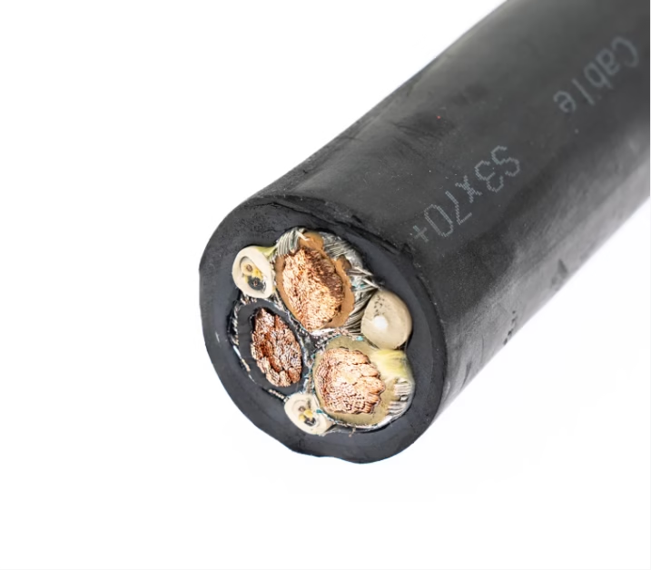
What is the Outer Diameter Difference Between 4G50 and 4×50 in NSHTÖU-J 0.6/1kV Cable Specifications?
A comprehensive engineering guide explaining the outer diameter differential between NSHTÖU-J 0.6/1kV 4G50 (four main power conductors plus integrated green/yellow earth conductor) and 4×50 (four main power conductors only) heavy-duty rubber reeling cable configurations. Covers the fundamental reasons why ground conductor integration increases cable diameter, conductor geometry and spacing implications, earth conductor positioning strategies for mechanical strength and electrical performance, complete component stack-up architecture for both configurations, electromagnetic field distribution effects, stress concentration reduction mechanisms, DIN VDE 0250-814 and IEC 60811 standards compliance frameworks, manufacturing tolerance windows and process control variations, practical cross-reference standards for global procurement and equipment compatibility, and critical field selection, sizing, and installation verification procedures for project engineers designing power distribution systems for port machinery, mining equipment, industrial cranes, and dynamic mechanical reeling applications. — 为NSHTÖU-J 0.6/1kV 4G50与4×50外径差异提供综合工程指南。
1. Direct Answer: Diameter Differential and Configuration Comparison 直接答案:外径差异与配置对比
The nominal outer diameter of NSHTÖU-J 4G50 (four 50 mm² power conductors plus one integrated green/yellow earth conductor, five total) is approximately 42.0–48.0 mm, whereas the equivalent 4×50 configuration (four 50 mm² power conductors only, four total, no dedicated earth conductor) is nominally approximately 38.5–44.5 mm, representing an outer diameter differential of roughly 3.5–4.0 mm in nominal specification ranges. This diameter increase in the 4G50 configuration reflects the spatial and mechanical requirements necessary to integrate the additional green/yellow earth conductor into the cable cross-section while maintaining proper insulation distances between all conductors, adequate mechanical spacing to distribute stress during high-speed reeling operations, and structural integrity under the extreme tensile loads encountered in port cranes, mining draglines, and industrial lifting applications. The 4G50 configuration typically exhibits copper content of approximately 1,920 kg/km (including the earth conductor), while 4×50 exhibits approximately 1,680–1,750 kg/km (earth conductor copper excluded), and total cable weight differs by approximately 300–400 kg/km, reflecting the substantial additional material required to safely integrate the fifth conductor. Both configurations comply with DIN VDE 0250-814 requirements for heavy-duty rubber reeling cables, but they serve different grounding architecture philosophies: the 4G50 is integrated-earth design (ground circuit built into the cable cross-section), while the 4×50 typically requires external earth/ground conductors or relies on external armor or cable tray grounding, making it more suitable for installations where ground paths can be established through equipment frames or external conductors.
Understanding this fundamental distinction is essential for project engineers because the choice between 4G50 and 4×50 does not merely represent an incremental diameter increase. Rather, it reflects two fundamentally different approaches to electrical grounding architecture, mechanical load distribution, and equipment integration strategy. This engineering guide will explore not only the numeric outer diameter difference but also the underlying physical and electrical reasons why that difference exists, and how to select the appropriate configuration for your specific application based on installation geometry, equipment constraints, and grounding system design.
2. Why Ground Conductor Designation Matters: The “G” vs. “x” Distinction 为什么接地线指示很重要:”G”与”x”的区别
Before diving into the detailed dimensional analysis, it is essential to understand what the designation letters “G” and “x” actually mean in the context of DIN VDE cable nomenclature. Many procurement specialists and field engineers confuse these designations or treat them as cosmetic variations, but they actually represent fundamentally different cable architectures with significant implications for installation design, cost, and operational safety.
2.1 The “G” Designation: Integrated Green/Yellow Earth Conductor “G”指示:集成绿/黄接地线
The “G” in “4G50” stands for “Grün” (German for “green”), more specifically “Grün-Gelb” (green-yellow), denoting that the cable includes an integrated green/yellow striped conductor specifically designated for earth/ground connection. This earth conductor is physically incorporated into the cable cross-section as a fifth conductor running parallel to the four main power conductors, insulated and protected with the same care as the main conductors, and included in the overall cable diameter and weight calculations. The green/yellow conductor typically has the same cross-sectional area as the main conductors (in the case of 4G50, the earth conductor is 50 mm² or sometimes slightly smaller such as 35–40 mm² depending on equipment grounding requirements). The presence of this integrated earth conductor means that the cable provides a complete grounding solution within its own cross-section—when connected, the green/yellow conductor automatically provides a protected ground path for connected equipment, eliminating the need for external earth conductors or reliance on cable tray grounding in many applications.
2.2 The “x” Designation: Power Conductors Only, No Integrated Earth “x”指示:仅电源导体,无集成接地线
The “x” in “4×50” represents a simplified designation meaning that the cable contains only the main power conductors (in this case, four 50 mm² conductors) with no integrated green/yellow earth conductor. This does not mean the cable provides no grounding capability—it means that grounding must be established through alternative means: an external earth conductor run alongside the 4×50 cable, the cable tray or support structure itself serving as the ground path, equipment frame bonding, or a dedicated grounding conductor installed separately. The “x” configuration is typically lighter, smaller in diameter, and less expensive than the equivalent “G” configuration because it eliminates the fifth conductor and the additional manufacturing steps required to integrate, insulate, and protect that conductor.
2.3 Why This Distinction Affects Cable Diameter Directly 为什么这种区别直接影响电缆直径
The difference between 4G50 and 4×50 is not merely a matter of adding a thin wire—adding a fifth conductor to a four-conductor cable requires careful geometric redesign of the entire cross-section. The four main 50 mm² conductors in a 4×50 cable are arranged in a specific geometric pattern (typically a square or rectangular arrangement) that optimizes space and allows proper insulation placement. Introducing a fifth 50 mm² conductor into the 4×50 cross-section requires either rearranging all five conductors into a new geometric pattern or placing the earth conductor in a specific position that maintains proper insulation distances and electrical safety. This geometric rearrangement necessarily increases the overall cable diameter because conductor cross-sections are roughly circular (approximately 8.0 mm diameter for a 50 mm² conductor), and packing five roughly-circular objects into a cable cross-section requires more space than packing four. Additionally, the presence of the earth conductor affects the mechanical load distribution during reeling operations—the cable must accommodate tensile and torsional forces acting on five conductors instead of four, requiring additional bedding material and protective layers to distribute stress evenly. These are not marginal adjustments but fundamental engineering changes that necessarily result in the 3.5–4.0 mm outer diameter increase observed between 4×50 and 4G50.
3. Understanding Conductor Architecture: Core Design Philosophy 理解导体架构:核心设计理念
To understand the dimensional difference between 4G50 and 4×50, it is helpful to understand the underlying design philosophy that governs conductor arrangement in heavy-duty reeling cables. This architecture is optimized not for static applications but for the extreme dynamic stresses encountered during continuous reeling operations at speeds of 100–180 m/min.
3.1 Four-Conductor Geometry in 4×50 4×50中的四导体几何
In the 4×50 configuration, the four 50 mm² conductors are typically arranged in a compact geometric pattern, often described as a square or modified square arrangement. Each conductor is approximately 8.0 mm in diameter (for 50 mm² of tinned Class 5 copper), and the four conductors are positioned with center-to-center spacing of approximately 10–12 mm, resulting in a minimum cross-sectional envelope of roughly 18–20 mm × 18–20 mm before insulation. When insulation (approximately 2.0–2.5 mm thickness on all sides) is applied around this four-conductor core, the resulting insulated conductor bundle occupies a space approximately 22–26 mm in diameter. After adding inner and outer protective jackets, bedding materials, and the outer rubber sheath (totaling approximately 4–6 mm thickness in all directions), the final outer diameter reaches 38.5–44.5 mm, consistent with the 4×50 nominal specification range.
3.2 Five-Conductor Geometry in 4G50 4G50中的五导体几何
The introduction of a fifth conductor (the green/yellow earth conductor) in the 4G50 configuration fundamentally changes the geometric arrangement. Rather than four conductors in a square pattern, the five-conductor cross-section typically employs a “core plus surround” geometry where four main conductors form the outer core and the earth conductor is positioned in the center, or more commonly, all five conductors are arranged in a modified pentagonal or spread pattern that maximizes spacing while minimizing the envelope diameter. However, because five conductors cannot be arranged as compactly as four conductors of the same size, the insulated conductor bundle with all five conductors now occupies a space approximately 26–30 mm in diameter before outer protection. After accounting for the same jacket and protective layers as the 4×50 configuration, the final outer diameter reaches 42.0–48.0 mm. The additional 3.5–4.0 mm diameter increase reflects the spatial requirement of the fifth conductor and the more complex geometric arrangement necessary to safely position five conductors with adequate insulation spacing.
3.3 Conductor Material and Flexibility 导体材料与柔韧性
It is important to note that both 4G50 and 4×50 employ Class 5 (fine-stranded) tinned copper conductors according to DIN VDE 0295 and IEC 60228 standards. Class 5 refers to the conductor strand count—approximately 100–150 individual strands per conductor, making the overall conductor extremely flexible despite the large 50 mm² cross-sectional area. This extreme fine-stranding is essential for reeling applications where the cable undergoes continuous bending at curves with a minimum radius of 6–8× the outer diameter. Both the main conductors and the earth conductor in the 4G50 configuration use this same fine-stranding approach, meaning the conductor bundle in 4G50 is no less flexible than 4×50 despite its larger diameter—the diameter increase reflects the addition of conductor volume, not any reduction in flexibility characteristics.
4. Earth Conductor Integration: Positioning and Spatial Implications 接地线集成:定位与空间含义
The green/yellow earth conductor in the 4G50 configuration is not simply an afterthought added to the periphery of the cable—its positioning, insulation, and protective treatment are engineered to fulfill specific electrical and mechanical functions. Understanding these functions illuminates why the conductor’s presence necessarily increases the cable’s outer diameter.
4.1 Earth Conductor Positioning Strategy 接地线定位策略
The earth conductor in 4G50 can be positioned in one of two primary configurations depending on the cable designer’s priorities. First, the “central core” approach positions the earth conductor in the geometric center of the four main conductors, physically surrounded by the four main power conductors. This arrangement provides excellent electromagnetic shielding—the earth conductor is less susceptible to external electromagnetic interference because the four main conductors physically shield it from external fields. However, this arrangement requires that the earth conductor be routed through the center of the cross-section, which complicates the manufacturing process. Second, the “distributed” or “outer integration” approach positions the earth conductor alongside the four main conductors in a pentagonal or spread pattern, where all five conductors are arranged with approximately equal spacing and symmetry. This arrangement simplifies manufacturing and provides superior mechanical load distribution during dynamic reeling—the earth conductor experiences the same tensile and torsional stress distribution as the main conductors because it is positioned symmetrically with them. For reeling cable applications, the distributed arrangement is typically preferred because it ensures that the earth conductor does not experience asymmetric loading that could cause premature fatigue or breakage.
4.2 Insulation and Protective Requirements 绝缘与保护要求
The earth conductor in 4G50 must be insulated with the same care and thickness as the main power conductors, even though its electrical function is grounding rather than power carrying. The insulation thickness (typically 2.0–2.5 mm around the earth conductor) serves multiple functions: electrical safety (preventing accidental phase-to-ground faults if the insulation is damaged), mechanical protection (the insulation acts as a cushion against mechanical damage), and color coding standardization (the green/yellow color is incorporated into or applied over the insulation to meet DIN VDE 0298 color coding standards). This insulation layer contributes significantly to the conductor’s overall diameter—the earth conductor itself is approximately 8.0–8.5 mm in diameter, and with 2.0–2.5 mm of insulation on all sides, the insulated earth conductor becomes approximately 12.0–13.5 mm in diameter. When five such insulated conductors must be packed into a cable cross-section with adequate spacing, the geometric envelope necessarily increases compared to four conductors.
4.3 Mechanical Stress Distribution and Bedding Material 机械应力分布与衬垫材料
A critical engineering function of the earth conductor is mechanical load sharing during dynamic reeling operations. When a cable carrying a 4G50 configuration reels onto a drum at 120 m/min under tension (typical for mining draglines or port cranes), each conductor experiences tensile stress and torsional shear. If the four main power conductors alone bore this stress, they would be concentrated in four points, creating stress concentration zones. The addition of the fifth earth conductor distributes this stress across five load-carrying paths, reducing the peak stress at any single conductor and extending cable service life. To achieve this stress distribution benefit, the earth conductor must be positioned such that it shares the load symmetrically—typically in a distributed pentagonal arrangement rather than a central core arrangement. This distributed arrangement requires additional bedding material (typically polyester or aramid tape or fiber) to fill the gaps between conductors and support the five-conductor bundle, effectively increasing the overall conductor assembly diameter before jacket application.
5. Component Stack-up Comparison: 4G50 versus 4×50 Layer Analysis 组件堆积对比:4G50与4×50层分析
To fully understand why 4G50 and 4×50 exhibit a 3.5–4.0 mm outer diameter differential, it is valuable to examine how each configuration builds its final dimensions through progressive addition of layers.
| Component Layer 组件层 | Nominal Thickness 名义厚度 | Cumulative Diameter Contribution 对直径的累积贡献 | Function 功能 |
|---|---|---|---|
| Four 50 mm² Class 5 tinned copper conductors (square/rectangular arrangement) 四根50 mm²第5类镀锡铜导体 | ~8.0 mm diameter each | ~18–20 mm envelope (center-to-center spacing) | Electrical power carrying; high flexibility for continuous reeling |
| Conductor insulation (EPR compound, ~2.2 mm per side) 导体绝缘 | ~4.4 mm total per conductor circumference | +~8.8 mm to envelope (adds to all sides) | Voltage isolation (0.6/1 kV); electrical stress distribution |
| Bedding and spacing material (polyester or aramid tape) 衬垫与间距材料 | ~0.8–1.2 mm cumulative | +~1.6–2.4 mm to diameter | Conductor bundle support; symmetrical load distribution during reeling |
| Inner protective jacket (rubber, typically neoprene) 内护套 | ~1.0–1.5 mm | +~2.0–3.0 mm to diameter | Moisture barrier; electrical stress leveling; mechanical interface |
| Anti-torsion braid (high-strength polyester or aramid fiber) 防扭转编织 | ~1.5–2.0 mm coverage | +~3.0–4.0 mm to diameter | Prevents Z-shaped cable twisting during high-speed reeling; torsional resistance |
| Outer rubber jacket (special heavy-duty chloroprene/PCP or equivalent) 外护套 | ~2.5–3.0 mm | +~5.0–6.0 mm to diameter | Abrasion resistance; UV protection; mechanical protection |
| Total accumulated layers (4×50) | Design nominal: ~38.5–44.5 mm | Standard tolerance typical: ±2.0–2.5 mm | Equipment integration dimension for applications requiring no dedicated earth |
Now examine the 4G50 configuration with the integrated fifth earth conductor:
| Component Layer 组件层 | Nominal Thickness 名义厚度 | Cumulative Diameter Contribution 对直径的累积贡献 | Function 功能 |
|---|---|---|---|
| Four 50 mm² Class 5 tinned copper main conductors (50 mm² each) 四根主导体 | ~8.0 mm diameter each | ~20–22 mm envelope (distributed/pentagonal arrangement) | Main electrical power carrying; Class 5 fine-stranding |
| One 50 mm² (or 35–40 mm²) green/yellow Class 5 earth conductor 一根接地线 | ~8.0 mm diameter (50 mm²) or ~7.0 mm (35–40 mm²) | Adds ~8.0 mm to envelope (integrated in pentagonal geometry) | Protective earth/ground; shared mechanical load bearing; color-coded green/yellow |
| Conductor insulation on all five conductors (EPR, ~2.2 mm per side) 所有五根导体的绝缘 | ~4.4 mm per conductor | +~8.8–9.6 mm to envelope (applied to five conductors) | Voltage isolation; electrical safety; stress distribution across five conductors |
| Bedding and spacing material (more complex for five-conductor geometry) 衬垫与间距材料 | ~1.2–1.8 mm cumulative | +~2.4–3.6 mm to diameter | Support of pentagonal five-conductor geometry; even stress distribution |
| Inner protective jacket (rubber, typically neoprene) 内护套 | ~1.0–1.5 mm | +~2.0–3.0 mm to diameter | Moisture barrier; electrical stress leveling; mechanical interface |
| Anti-torsion braid (high-strength polyester or aramid fiber) 防扭转编织 | ~1.5–2.0 mm coverage | +~3.0–4.0 mm to diameter | Prevents cable twisting during reeling; accommodates five-conductor load distribution |
| Outer rubber jacket (special heavy-duty chloroprene/PCP) 外护套 | ~2.5–3.0 mm | +~5.0–6.0 mm to diameter | Abrasion resistance; UV protection; mechanical protection for five-conductor bundle |
| Total accumulated layers (4G50) | Design nominal: ~42.0–48.0 mm | Standard tolerance typical: ±2.0–2.5 mm | Equipment integration dimension with integrated earth conductor |
The comparison between Tables 1 and 2 illustrates a crucial point: the 3.5–4.0 mm diameter differential between 4×50 and 4G50 does not arise solely from adding one thin conductor. Rather, it reflects the cumulative effect of accommodating a fifth conductor throughout the cable architecture. The addition of the earth conductor increases the conductor bundle envelope by approximately 8.0 mm (adding one 8 mm diameter conductor to a four-conductor arrangement), but more significantly, it requires rearrangement of the entire geometric layout to accommodate five conductors symmetrically, adding approximately 2.0–3.0 mm to the initial envelope. The bedding material required to support the five-conductor geometry adds an additional 0.8–1.2 mm compared to four-conductor bedding. These incremental additions compound, resulting in the final 3.5–4.0 mm diameter differential. Additionally, the insulation, inner jacket, anti-torsion braid, and outer jacket layers must all be applied to the larger five-conductor bundle, so each protective layer contributes slightly more thickness to the final O.D. of 4G50 compared to 4×50.
6. Mechanical Stress Distribution: Why Extra Conductors Affect Outer Diameter 机械应力分布:为什么额外导体影响外径
One might reasonably ask: if the earth conductor performs the same electrical function as any of the main conductors, why must the cable diameter increase so significantly to accommodate it? The answer lies in the unique mechanical demands of reeling cable applications, where the cable experiences simultaneous tensile stress, torsional shear, and bending stress at rates far exceeding static cable applications.
6.1 Tensile Load Concentration in Four-Conductor Cables 四导体电缆中的拉伸应力集中
When a 4×50 cable is under tension—for example, supporting a load at the end of a port crane boom—the tensile force is distributed among four main power conductors. If each conductor is rated for approximately 100 N/mm² of tensile stress (a typical value for Class 5 tinned copper), the four-conductor configuration can sustain approximately 400 N/mm² total, distributed across the four conductors. However, because the four conductors occupy a relatively compact space (approximately 18–20 mm envelope), the stress concentration at the conductor-insulation interface is high. The insulation material must accommodate stress gradients across its thickness, potentially leading to localized mechanical fatigue over extended reeling cycles.
6.2 Stress Redistribution with Five Conductors 五导体的应力再分配
When a 4G50 cable includes a fifth earth conductor in a distributed pentagonal arrangement, the same tensile load is now shared among five conductors rather than four. This changes the fundamental stress distribution pattern. The five-conductor arrangement necessarily occupies a larger envelope (approximately 26–30 mm before insulation), but this larger envelope provides a distributed load path where each conductor experiences slightly lower peak stress. More significantly, the pentagonal arrangement creates a more symmetric stress distribution pattern—the four main conductors are no longer clustered in a compact square arrangement, but are spread around the earth conductor, reducing the stress concentration gradient that occurs at the conductor-insulation interface. This distributed stress pattern significantly extends the cable’s service life under continuous reeling cycles, particularly for draglines and cranes that may perform thousands of reeling operations daily.
6.3 Torsional Resistance and Anti-Twist Geometry 抗扭性与防扭几何
Heavy-duty reeling cables must resist “Z-shaped twisting”—a phenomenon where the cable rotates around its long axis during reeling operations, particularly when the cable is unsupported over long spans or when the reeling speed suddenly changes. This twisting causes stress concentration in the outer jacket and anti-torsion braid, and can eventually cause the cable structure to degrade. The anti-torsion braid (high-strength polyester or aramid fiber) is engineered to resist this twisting, but its effectiveness depends on the cable’s cross-sectional symmetry. A four-conductor cable has a specific symmetry, and the anti-torsion braid is engineered accordingly. A five-conductor cable has a different symmetry, requiring a different braid pattern and density to achieve equivalent torsional resistance. The slightly larger diameter of 4G50 (compared to 4×50) allows for an anti-torsion braid with superior torsional resistance properties because the larger circumference provides more space for braid strands without reducing braid density.
7. DIN VDE 0250-814 Standards: Tolerance Frameworks and Compliance Requirements DIN VDE 0250-814标准:容差框架与合规要求
The specifications for NSHTÖU-J 4G50 and 4×50 are established within the framework defined by DIN VDE 0250-814, which establishes dimensional, electrical, and mechanical requirements for heavy-duty rubber reeling cables. Understanding the standard’s tolerance framework helps clarify why both configurations have specific diameter ranges rather than exact fixed diameters.
DIN VDE 0250-814 permits outer diameter variation of approximately ±2.0–2.5 mm for cables in the 40–50 mm nominal diameter range, acknowledging that the extrusion process (by which the rubber jacket is applied) is inherently subject to process variations. Temperature fluctuations in the extrusion head, variations in line speed, differences in material batch properties, and cooling rate variations all influence the final jacket thickness and therefore the outer diameter. However, the standard requires that manufacturers maintain geometric dimensional precision and achieve target outer diameter specifications through rigorous process control. The nominal specification ranges provided in procurement documents (4G50: 42.0–48.0 mm, 4×50: 38.5–44.5 mm) represent the expected production envelope accounting for standard manufacturing variations, not arbitrary values. Manufacturers who consistently achieve tighter tolerance (±1.0–1.5 mm rather than ±2.0–2.5 mm) typically advertise this as a quality advantage because it reduces compatibility issues when routing cables through cable trays or terminating connections designed around nominal specifications.
8. Manufacturing Implications: Real-World Production Diameter Variation 制造含义:实际生产直径变化
The theoretical diameter specifications for 4G50 and 4×50 are one thing; understanding how real-world manufacturing processes actually achieve these specifications is quite another. Production engineers and project procurement specialists should understand the process variations that occur during cable manufacturing.
Both 4G50 and 4×50 configurations are manufactured using essentially identical extrusion processes: the insulated conductor bundle (either four or five conductors depending on configuration) is fed through an extrusion head where hot rubber (special heavy-duty chloroprene or equivalent material) is continuously applied around the bundle. The jacket thickness is determined by the gap between the conductor bundle and the extrusion die opening—this gap is set during extrusion head assembly and is typically maintained constant by precision mechanical positioning. However, process variations inevitably occur: the temperature of the rubber in the extrusion head varies by ±3–5°C depending on ambient conditions and production rate, which affects the rubber’s viscosity and how uniformly it flows around the conductor bundle. Line speed (the rate at which the cable moves through the extrusion station) varies by ±2–5% depending on downstream tension requirements and take-up equipment performance. Material batch variations in the rubber formulation can cause the final rubber thickness to vary by ±0.2–0.4 mm compared to nominal. These process variations are normal and expected—manufacturers design their processes to accommodate them while still meeting the standard tolerance envelope. Precision cable manufacturers employ real-time laser diameter measurement systems that continuously monitor the cable diameter during extrusion, allowing operators to make immediate adjustments to the extrusion head gap or line speed if the cable drifts outside acceptable tolerance. This real-time feedback control is what allows manufacturers to consistently produce cables within ±1.5 mm of nominal specification.
9. Cross-Reference Specifications: International Cable Equivalents and Compatibility 交叉参考规格:国际电缆等效与兼容性
Project managers and procurement engineers frequently encounter situations where original cable specifications (such as NSHTÖU-J 4G50) are unavailable or where cost optimization suggests substituting an equivalent international cable. Understanding cross-reference specifications helps ensure that alternative cables truly meet equipment requirements rather than merely appearing compatible on paper.
| NSHTÖU-J Configuration NSHTÖU-J配置 | Equivalent International Standard/Brand 国际标准/品牌等效 | Cross-Reference Model 交叉参考型号 | Diameter Match 直径匹配 | Key Compatibility Note 关键兼容性说明 |
|---|---|---|---|---|
| NSHTÖU-J 4G50 4G50集成接地线 | Prysmian (普睿司曼) | CORDAFLEX (SMK) 4×50 + G/Y | 42–48 mm nominal | Full equivalent; DIN/IEC compatible; integrated earth conductor |
| NSHTÖU-J 4G50 | TF Kable (波兰) | TFCrane NSHTÖU-J 4x50G | 42–48 mm nominal | Direct equivalent; identical DIN 0250-814 compliance |
| NSHTÖU-J 4G50 | Tratos (西班牙) | TRATOSFLEX 4G50 | 42–48 mm nominal | Equivalent with identical earth integration; typical weight ±50 kg/km variance |
| NSHTÖU-J 4G50 | Feichun Special Cable (飞纯特种电缆) | Trommelflex (K) 4G50 | 42–48 mm nominal | China-manufactured equivalent; DIN certified; cost-optimized variant |
| NSHTÖU-J 4×50 (no earth) 4×50仅四导体 | Prysmian | CORDAFLEX 4×50 (standard) | 38.5–44.5 mm nominal | Four conductors only; requires external earth conductor routing |
| NSHTÖU-J 4×50 | TF Kable | TFCrane NSHTÖU 4×50 (without G/Y) | 38.5–44.5 mm nominal | Direct equivalent; no integrated earth; lighter diameter |
When substituting cables, project engineers must verify that the replacement cable meets all critical parameters: outer diameter compatibility with equipment design, current-carrying capacity under actual ambient conditions, mechanical properties (minimum bending radius, tensile strength), and electrical properties (voltage rating, insulation test voltage). It is insufficient to match only the cross-sectional area (50 mm²) and conductor count (4) or (4+earth)—the replacement cable’s entire specification must be validated, particularly the outer diameter, because terminal connections, cable tray routing, and reeling drum design are often precisely dimensioned around the nominal cable specifications. A cable that is 2–3 mm larger than expected may not fit into terminal lugs or connector interfaces; similarly, a cable that is smaller than expected may require oversized routing supports or may be incompatible with cable tray systems designed for the nominal diameter.
10. Field Selection and Sizing: How to Choose Between 4G50 and 4×50 现场选择与尺寸确定:如何在4G50和4×50之间选择
For project engineers designing power distribution systems for port machinery, mining equipment, or industrial cranes, the choice between NSHTÖU-J 4G50 and 4×50 should be based on systematic analysis of grounding architecture requirements, installation geometry constraints, and equipment design considerations. This section provides a practical decision framework.
10.1 Select 4G50 When… 选择4G50当…
Choose the 4G50 integrated-earth configuration when your installation design requires a complete, protected ground path carried within the power cable itself. This is appropriate when the equipment being powered has no other reliable ground path (for example, portable drill rigs or mobile excavators where the equipment may not be in reliable electrical contact with ground through the structure), when the cable must be compatible with stringent electrical safety standards (such as Class I Division 1 hazardous zone installations where ground continuity is mandatory), when the cable runs through multiple transfer points or cable carriers where maintaining consistent ground path would be difficult with an external earth conductor, or when the equipment design includes integrated ground fault detection and the ground conductor must be continuously available throughout the cable run. The additional 3.5–4.0 mm diameter and 240–280 kg/km additional weight of 4G50 are justified by the grounding assurance and the simplified installation these provide.
10.2 Select 4×50 When… 选择4×50当…
Choose the 4×50 four-conductor configuration when the equipment being powered has alternative grounding paths that are established through other means. This is appropriate when the equipment is stationary and can be grounded through the building or structural ground system, when a separate external earth conductor can be reliably routed alongside the 4×50 power cable (and that external conductor is properly sized and protected), when the equipment design includes cable tray or support structure grounding where the cable runs continuously in contact with conductive metal structures that serve as the ground path, or when cost optimization is a primary design objective and the installation architecture can reliably provide grounding through alternative means. The 4×50 configuration offers approximately 12–15% cost savings compared to 4G50 and has a slightly smaller diameter (beneficial for space-constrained routing), making it attractive when grounding can be assured through other means.
10.3 Verification Procedure 验证程序
Before finalizing your cable selection, implement a systematic verification procedure: First, document the equipment’s grounding requirements—check the equipment manual and electrical schematic for ground conductor specifications and required ground continuity. Second, identify all possible ground paths in your installation—cable tray bonding, equipment frame bonding, building ground system, or separate ground conductors. Third, calculate the required earth conductor cross-sectional area using the formula from IEC 60364-5-54 or VDE 0100: the earth conductor area should be at least 50% of the phase conductor area (for a 50 mm² phase conductor, minimum earth conductor area is 25 mm²). Fourth, if only external earth conductors can provide this grounding, verify that you can reliably route and protect an earth conductor of adequate size alongside the power cable. Fifth, make your selection: if external grounding is feasible, choose 4×50 for cost optimization; if external grounding is problematic or if equipment design requires integrated earth, choose 4G50 for grounding assurance.
11. Installation Verification and Equipment Compatibility Checking 安装验证与设备兼容性检查
After procuring either 4G50 or 4×50 cable, implement verification procedures to confirm that the received cable meets specification and is compatible with all equipment and installation requirements.
Measure the cable’s outer diameter at a minimum of 10 locations along the delivery length (for example, at 50 m intervals for a 500 m reel). Use a precision digital caliper or micrometer, measuring at multiple rotational positions (top, bottom, and sides) to detect asymmetry in the jacket application or bedding layer. Record all measurements and calculate minimum, maximum, mean, and standard deviation. For 4G50, verify that all measurements fall within the tolerance range 42.0–48.0 mm (ideally within ±1.5 mm of 45.0 mm nominal for best equipment compatibility). For 4×50, verify measurements fall within 38.5–44.5 mm (ideally within ±1.5 mm of 41.5 mm nominal). If any measurements deviate beyond these ranges, contact the manufacturer before installation—undersized cables may not seat properly in terminal lugs or connector interfaces, while oversized cables may create mechanical stress when terminating or routing. Additionally, perform visual inspection of the conductor configuration: for 4G50 cable, carefully examine the conductor cross-section to confirm the presence and proper positioning of the green/yellow earth conductor; for 4×50 cable, confirm that only four main conductors are present. Test the cable’s flexibility by hand-coiling it at the minimum bending radius specified (6–8× the O.D.), confirming that the cable flexes smoothly without developing kinks or flat spots that would indicate damage or improper manufacturing.
References & Sources 参考来源
- DIN VDE 0250-814 — “Cables; rubber sheathed; reeling cables; 0.6/1 kV; general, test methods.” Verband der Elektrotechnik Elektronik Informationstechnik. Establishes dimensional, electrical, and mechanical specifications for (N)SHTÖU-J and equivalent heavy-duty reeling cables.
- DIN VDE 0295 — “Conductors of insulated cables.” Specifies conductor material, stranding, and quality requirements for Class 5 (fine-stranded) copper conductors.
- IEC 60228 — “Conductors of insulated cables” (international equivalent to DIN VDE 0295). Class 5 conductor specifications and international compatibility.
- DIN VDE 0298-4 — “Maximum permissible current” tables for cables. Provides current-carrying capacity tables and de-rating factors for ambient temperature and installation method variations.
- IEC 60364-5-54 — “Earthing arrangements, protective conductors and protective bonding conductors.” Specifies earth conductor sizing requirements based on phase conductor cross-section.
- DIN VDE 0100 (VDE 0100) — “Electrical installations of buildings” (German National Standard). Provides comprehensive electrical installation design requirements including ground system design.
- IEC 60811 — “Insulation and sheath materials of cables. Test methods for non-metallic materials.” Establishes testing procedures for rubber insulation and jacket materials used in reeling cables.
- DIN EN ISO 1402 — “Rubber hoses and hose assemblies — Wire- or cord-reinforced — Specification.” Relevant for understanding reinforcement layer specifications in armored reeling cables.
Contact Technical Support for Cable Selection and Sizing 联系技术支持获取电缆选择与尺寸确定
For NSHTÖU-J 0.6/1kV heavy-duty rubber reeling cable specifications, detailed comparison between 4G50 (integrated earth) and 4×50 (four-conductor) configurations, outer diameter and component specifications, current-carrying capacity calculations, installation verification procedures, cross-reference standards and international cable equivalents, grounding system design consultation, cable selection and sizing guidance for your specific port machinery, mining equipment, or industrial crane applications, or comprehensive technical support ensuring optimal cable performance and long-term reliability in extreme reeling environments, contact our engineering support team. We provide complete dimensional data, certification documentation, installation engineering, and specialized support for heavy-duty mechanical applications. 如需NSHTÖU-J电缆规格、4G50与4×50对比、外径详情或技术指导,请直接联系我们的工程支持团队。


