(N)TSCGEWOEU and (N)TSKCGEWOEU refers to specialized cable constructions utilizing EPR (Ethylene Propylene Rubber) insulation with unique PROTOFIRM sandwich design technology, providing superior mechanical resilience and electrical reliability for motorized cable reel applications.

WX-10 Round High Voltage Reeling Cable
Introduction to WX-10 High Voltage Reeling Cables
The WX-10 series represents the pinnacle of high voltage reeling cable technology, specifically engineered for demanding applications in container cranes, mining equipment, stackers, reclaimers, and ship unloaders. Manufactured by Anhui Feichun Special Cable Co., Ltd., these cables incorporate advanced materials and design principles to deliver exceptional performance in extreme operating conditions.
The designation (N)TSCGEWOEU and (N)TSKCGEWOEU refers to specialized cable constructions utilizing EPR (Ethylene Propylene Rubber) insulation with unique PROTOFIRM sandwich design technology, providing superior mechanical resilience and electrical reliability for motorized cable reel applications.
Primary Purpose and Applications
WX-10 cables are specifically designed for high-performance cable reel systems where extreme mechanical stresses, continuous operation, and harsh environmental conditions are the norm. These cables excel in applications requiring simultaneous flexing, torsional stress, and high-speed travel movements.
Main Applications
Main power supply for ship-to-shore cranes operating at fast travel speeds with high mounting locations
Heavy-duty machinery in both surface and underground mining operations requiring reliable power transmission
Material handling equipment in bulk storage facilities with demanding duty cycles
Port equipment requiring continuous operation through multiple diversion roller assemblies
Primary application for high-speed winding and unwinding operations up to 240 m/min
Ideal Operating Scenarios
WX-10 cables are the optimal choice when:
- Medium to high dynamic loads are expected during reel operation
- Continuous operation under high mechanical loads is anticipated
- A reliable, robust, and very durable cable solution is required
- The cable must operate through several diversion roller assemblies
- Maximum equipment availability is the most important criterion
- Operating temperatures can reach down to -35°C
Key Technical Characteristics
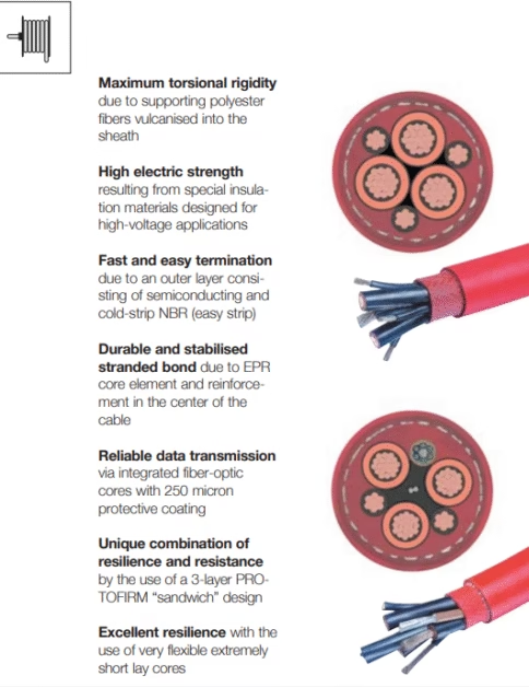
⚡ Maximum Torsional Rigidity
Supporting polyester fibers are vulcanized directly into the sheath, creating an integrated reinforcement structure that resists twisting and maintains cable integrity during complex movements.
🔋 High Electric Strength
Special EPR insulation materials designed specifically for high-voltage applications provide exceptional dielectric properties at voltages up to 20 kV and beyond.
🔧 Fast Termination
Outer layer features semiconducting and cold-strip NBR (easy strip) design, enabling quick and reliable field terminations without specialized tools or hot-stripping equipment.
💪 Durable Stranded Bond
EPR core element with central reinforcement creates a stabilized stranded structure that maintains conductor integrity through millions of flex cycles.
📡 Reliable Data Transmission
Integrated fiber-optic cores with 250-micron protective coating enable high-speed data communication alongside power transmission (TSKCGEWOEU variants).
🛡️ PROTOFIRM Sandwich Design
Unique 3-layer construction combines resilience with wear resistance through a vulcanized polyester braid sandwiched between inner and outer sheaths.
Material Structure and Construction
Conductor Design
The conductor represents the foundation of the cable’s electrical performance. WX-10 cables utilize highly flexible, finely stranded tin-plated electrolytic copper that exceeds Category 5 specifications according to DIN VDE 0295. This ultra-fine stranding provides exceptional flexibility while maintaining excellent electrical conductivity.
Conductor Features:
- Tin-plated electrolytic copper for corrosion resistance and superior termination
- Finely stranded construction exceeding DIN VDE 0295 Category 5
- Layered stranding with lay factor of 7 × D (core diameter)
- Earth conductor divided into three parts in interstices (standard) or halved (fiber optic variants)
- Black insulation with white numbering for easy identification
Insulation System
The insulation system is critical for high-voltage performance. WX-10 cables employ Ethylene-Propylene-Rubber (EPR) as the base insulation material, selected for its superior electrical and mechanical properties. According to research, EPR insulation demonstrates high dielectric strength, excellent ozone and weathering resistance, and maintains performance across a wide thermal range from -55°C to 150°C. EPR also exhibits superior resistance to electrical treeing in the presence of moisture compared to alternative materials, making it ideal for harsh industrial environments.
The insulation meets high-voltage quality standards (minimum 3GI3 grade) and incorporates field control layers:
- Inner semiconducting layer: EPR-based compound for uniform field distribution
- Core insulation: High-purity EPR optimized for high-voltage applications
- Outer semiconducting layer: NBR-based compound designed for cold stripping
Sheathing System – PROTOFIRM Technology
The revolutionary three-layer PROTOFIRM sandwich structure provides unmatched mechanical protection:
- Inner Sheath: Red EPR compound (5GM3 rating, submersible quality) provides electrical insulation and chemical resistance
- Reinforcement Layer: Polyester fiber braid vulcanized between sheaths provides torsional rigidity and tensile strength
- Outer Sheath: High wear-resistant PCP (polychloroprene) compound (5GM5 rating) in bright red color delivers exceptional abrasion and tear resistance
Sheath Material Properties:
- PCP (Polychloroprene) base: Excellent resilience and flexibility
- High wear resistance: Extended service life in harsh conditions
- Oil resistant: Suitable for industrial environments
- UV resistant: Can be used outdoors without degradation
- Bright red color: High visibility for safety
Fiber Optic Integration (TSKCGEWOEU Variants)
For applications requiring data transmission, TSKCGEWOEU cables integrate fiber optic elements directly into the cable structure:
- 6 fiber optic cores with 250-micron protective coating
- Positioned in the third interstice of the cable core
- Protected from mechanical stress while maintaining flexibility
- Enables real-time monitoring and control communication
Electrical Parameters and Specifications
| Parameter | 6.0/10.0 kV | 8.7/15.0 kV | 12.0/20.0 kV |
|---|---|---|---|
| Rated Voltage (Uo/U) | 6.0/10.0 kV | 8.7/15.0 kV | 12.0/20.0 kV |
| Max AC Operating Voltage | 7.0/12.0 kV | 10.2/18.0 kV | 14.0/24.0 kV |
| Max DC Operating Voltage | 9.0/18.0 kV | 13.0/26.0 kV | 18.0/36.0 kV |
| Test Voltage | According to DIN VDE 0250 part 813 | ||
Mechanical Performance Specifications
| Parameter | Specification |
|---|---|
| Travel Speed | Up to 240 m/min (>240 m/min on request) |
| Static Bending Radius | 6 × cable diameter |
| Bending Radius on Reel | 12 × cable diameter |
| Bending Radius at Diversion Rollers | 15 × cable diameter |
| Bending Radius at S-Track Curve | 20 × cable diameter |
| Torsional Stress | ± 25°/m |
| Tensile Load Capacity | 20 N/mm² during operation |
Thermal Operating Parameters
| Condition | Temperature Range |
|---|---|
| Flexing Applications | -35°C to +60°C |
| Fixed Installation | -50°C to +80°C |
| Maximum Conductor Operating Temperature | 90°C |
| Short-Circuit Temperature | 200°C |
Compliance with International Standards
WX-10 cables are designed and manufactured in accordance with multiple international standards, ensuring compatibility and safety across global markets:
Standard Compliance Details
DIN VDE 0250 part 813: This fundamental German standard governs flexible cables with rubber insulation for heavy mechanical service. It specifies construction requirements, testing procedures, and performance criteria for high-voltage reeling cables used in demanding applications.
DIN VDE 0295: Defines conductor classes and stranding requirements. WX-10 cables exceed Category 5 specifications, providing maximum flexibility through ultra-fine stranding that surpasses standard requirements.
IEC 60332-1 / EN 60332-1-2: International flame retardancy standards. WX-10 cables meet these requirements, ensuring self-extinguishing properties that prevent fire propagation in the event of thermal exposure.
Safety Thresholds and Ampacity
Current Carrying Capacity (Ampacity)
Ampacity values are calculated for an ambient temperature of 30°C with a monospiral reel coil at 100% duty cycle. The following table provides ampacity data for standard conductor sizes:
| Conductor Size | 6/10 kV | 8.7/15 kV | 12/20 kV |
|---|---|---|---|
| 3 × 25 mm² | 104.8 A | 111.2 A | 111.2 A |
| 3 × 35 mm² | 129.6 A | 137.6 A | 137.6 A |
| 3 × 50 mm² | 161.6 A | 172.8 A | 172.8 A |
| 3 × 70 mm² | 200.0 A | 212.0 A | 212.0 A |
| 3 × 95 mm² | 240.8 A | 255.2 A | 255.2 A |
| 3 × 120 mm² | 281.6 A | 296.8 A | 296.8 A |
| 3 × 150 mm² | 323.2 A | 342.4 A | 342.4 A |
⚠️ Important Ampacity Considerations
The published ampacity values are based on specific reference conditions. Varying environmental factors, operational methods, and cable arrangements can result in considerably different current-carrying capacities. Consult the manufacturer’s technical documentation for derating factors applicable to your specific installation.
- Temperature Derating: Ambient temperatures above 30°C require derating
- Duty Cycle: Intermittent operation may allow higher currents
- Cable Grouping: Multiple cables on the same reel reduce individual capacity
- Reel Configuration: Tightly wound coils have lower ampacity than loosely wound
Permitted Tensile Loads
Maximum permissible tensile forces during operation vary by conductor size:
- 25 mm²: 1,500 N
- 35 mm²: 2,100 N
- 50 mm²: 3,000 N
- 70 mm²: 4,200-5,250 N (voltage dependent)
- 95 mm²: 5,700 N
- 120 mm²: 7,200 N
- 150 mm²: 9,000 N
Voltage Safety Margins
WX-10 cables incorporate substantial safety margins in their voltage ratings:
- Maximum permitted operating voltage exceeds rated voltage by 20%
- AC test voltages applied during manufacturing ensure dielectric integrity
- DC operating voltages approximately 50% higher than AC ratings
- Semiconducting layers provide uniform field distribution, preventing corona discharge
Precautions for Use and Installation
Pre-Installation Inspection
Critical Pre-Use Checks
- Visual Inspection: Examine the entire cable length for cuts, abrasions, kinks, or damage to the outer sheath. Any visible damage may compromise electrical safety and mechanical performance.
- Diameter Verification: Confirm the cable diameter matches specifications for your reel system. Oversized cables may not wind properly; undersized cables may slip.
- Storage Conditions: Verify the cable has been stored within temperature specifications (-35°C to +60°C). Extreme storage temperatures may affect material properties.
- Drum Inspection: Check that shipping drums are undamaged and cable ends are properly sealed to prevent moisture ingress.
Bending Radius Requirements
Maintaining proper bending radii is critical for cable longevity and safety. Violation of minimum bending radius specifications will result in premature failure:
Minimum Bending Radii (multiply by cable outer diameter):
- Static Installation: 6 × Ø – For fixed bends in the cable route
- On Cable Reel: 12 × Ø – Minimum drum diameter for reeling applications
- At Diversion Rollers: 15 × Ø – For guide rollers and sheaves
- S-Track Curves: 20 × Ø – For reverse bending in festoon systems
Example Calculation: For a cable with 60mm outer diameter on a reel application: Minimum drum diameter = 12 × 60mm = 720mm (minimum radius = 360mm)
Installation Guidelines
Cable Reel Configuration
- Drum Selection: Ensure the drum diameter meets or exceeds 12 × cable diameter
- Flanges: Reel flanges should extend at least 75mm beyond the wound cable on each side
- First Layer: The first layer must be wound tightly and evenly to prevent subsequent layers from crushing into gaps
- Layer Separation: Consider using separator discs between layers for high-speed applications (>180 m/min)
- Securing: Properly secure cable ends to prevent unspooling under operational loads
Termination Procedures
WX-10 cables feature cold-strip NBR semiconducting layers for simplified termination:
- Preparation: Clean the cable end and mark stripping lengths according to termination specifications
- Outer Sheath Removal: Remove the PCP outer sheath carefully to avoid damaging inner layers
- Shield Preparation: Fold back any metallic shields or earth conductors
- Semiconducting Layer Removal: The outer semiconducting NBR layer can be stripped cold (no heat required) – peel back carefully
- Insulation: Do not damage the EPR insulation during stripping operations
- Conductor Preparation: Clean and prepare conductor ends according to lug or connector specifications
- Stress Relief: Install proper stress relief boots or bending protectors at termination points
Operational Precautions
⚠️ Critical Operating Warnings
- Never Exceed Speed Limits: Maximum travel speed is 240 m/min unless specifically rated otherwise. Higher speeds generate excessive heat and accelerate wear.
- Avoid Overloading: Do not exceed rated ampacity. Overloading causes insulation degradation and potential failure.
- Monitor Temperature: In continuous duty applications, verify conductor temperature remains below 90°C during operation.
- Inspect Regularly: Establish a routine inspection schedule to identify wear, damage, or deterioration before failure occurs.
- Prevent Mechanical Damage: Protect cables from sharp edges, crushing, excessive pulling forces, and impact damage.
- Chemical Exposure: While oil-resistant, avoid unnecessary exposure to aggressive chemicals not covered in specifications.
- Water Ingress: Although suitable for water use, ensure terminations are properly sealed to prevent water ingress into conductor strands.
Environmental Considerations
WX-10 cables are designed for harsh environments, but observe these precautions:
- Low Temperature Operation: At temperatures below -20°C, allow cables to “warm up” through low-speed operation before full-load use
- High Temperature: In ambient temperatures above 45°C, derate ampacity according to manufacturer guidelines
- UV Exposure: While UV-resistant, minimize prolonged direct sunlight exposure when not in use
- Salt Atmosphere: In marine environments, increase inspection frequency for corrosion on exposed metallic components
- Dust and Particles: In dusty environments (mining, bulk handling), ensure cable reels have adequate cleaning systems
Common Problems and Troubleshooting
1. Premature Sheath Wear
Symptoms: Visible wear patterns, abrasion marks, or thinning of the outer red PCP sheath.
Causes:
- Inadequate bending radius at diversion rollers
- Rough or damaged roller surfaces
- Contamination (sand, grit) between cable and rollers
- Excessive travel speed for the application
- Improper cable routing causing rubbing
Solutions:
- Verify all bending radii meet minimum specifications (15 × Ø for diversion rollers)
- Inspect and replace worn or damaged rollers immediately
- Implement regular cleaning of rollers and cable path
- Install roller cleaning systems in dusty environments
- Review and optimize cable routing to eliminate unnecessary bending points
2. Conductor Breakage
Symptoms: Intermittent power loss, complete circuit failure, or visible conductor damage upon inspection.
Causes:
- Excessive tensile loads exceeding specifications
- Bending radius violations causing metal fatigue
- Improper spooling creating sharp bends or kinks
- Cyclic loading beyond design parameters
- Corrosion of conductor strands (usually from water ingress)
Solutions:
- Calculate and verify actual tensile loads remain within permitted values (20 N/mm²)
- Audit all bending points to ensure compliance with minimum radii
- Retrain operators on proper cable handling and spooling procedures
- Install load monitoring systems to prevent overload conditions
- Ensure all terminations are properly sealed against moisture
3. Insulation Breakdown
Symptoms: Ground faults, reduced insulation resistance, arcing, or complete short-circuit failure.
Causes:
- Mechanical damage penetrating to insulation layer
- Prolonged operation above maximum temperature (90°C conductor temperature)
- Water ingress through damaged sheath or unsealed terminations
- Exceeding voltage ratings during transient conditions
- Improper termination causing stress concentration
Solutions:
- Implement routine insulation resistance testing (megger testing)
- Monitor conductor temperatures during operation, especially in continuous duty
- Replace cables with visible mechanical damage immediately
- Install surge protection for applications with frequent voltage transients
- Ensure terminations are performed by qualified personnel following manufacturer specifications
4. Overheating During Operation
Symptoms: Cable feels hot to touch (above ambient + 60°C), thermal discoloration of sheath, or premature aging.
Causes:
- Operating current exceeds ampacity for installation conditions
- Insufficient cooling due to tight winding on reel
- Ambient temperature higher than design basis (30°C)
- Poor electrical connections at terminations creating resistance
- Multiple cables on same reel without derating
Solutions:
- Verify actual operating current against derated ampacity for your installation
- Apply appropriate derating factors for ambient temperature, duty cycle, and cable arrangement
- Inspect terminations for proper contact; remake poor connections
- Increase drum diameter to reduce packing density and improve cooling
- Consider forced ventilation for continuously loaded reels in enclosed spaces
5. Fiber Optic Signal Degradation (TSKCGEWOEU Variants)
Symptoms: Increased bit error rate, signal loss, or complete communication failure.
Causes:
- Excessive bending causing microbending losses in optical fibers
- Physical damage to fiber protective coating
- Water ingress affecting optical properties
- Connector contamination or damage
- Improper fiber termination
Solutions:
- Test fiber optic performance with OTDR (Optical Time Domain Reflectometer)
- Verify bending radii are maintained throughout cable route
- Inspect and clean fiber optic connectors
- Replace cables with visible physical damage to outer sheath
- Ensure fiber terminations are performed by certified fiber optic technicians
6. Torsional Damage
Symptoms: Spiral ridging visible on outer sheath, uneven spooling, or “corkscrew” appearance.
Causes:
- Exceeding ±25°/m torsional stress limit
- Improper installation creating twist in the cable
- Reel design allowing rotation during payout/retraction
- Asymmetric loading or unbalanced mechanical systems
Solutions:
- Verify reel system design prevents torsional loading
- Install cable guides and rollers to maintain proper orientation
- Check for equipment misalignment creating rotational forces
- During installation, ensure cable is laid without pre-twist
- The PROTOFIRM construction provides superior torsion resistance, but limits must still be respected
Maintenance and Inspection Schedule
Daily Visual Inspection (for critical applications)
- Check for visible damage, cuts, or abrasions on exposed cable sections
- Verify proper spooling without overlapping or crossover
- Inspect roller assemblies for damage, wear, or contamination
- Confirm cable guides and supports are secure and properly positioned
Monthly Detailed Inspection
- Measure insulation resistance (megger test) and compare to baseline values
- Inspect terminations for signs of overheating, corrosion, or loosening
- Check cable for signs of overheating or unusual thermal patterns
- Verify bending radii at all critical points
- Document any wear patterns or areas of concern
- Test fiber optic performance (TSKCGEWOEU variants)
Annual Comprehensive Assessment
- Complete electrical testing including high-voltage insulation testing
- Detailed mechanical inspection of entire cable length
- Roller and guide system assessment and replacement if necessary
- Review operational data (duty cycles, temperatures, speeds) against design parameters
- Forecast remaining service life based on wear patterns and usage
- Plan for cable replacement if approaching end of service life
Design Code Nomenclature
Understanding the cable designation provides insight into its construction:
(N)TSCGEWOEU / (N)TSKCGEWOEU Breakdown:
- (N) = Adapted to a national standard
- T = Heavy-duty cable (German: Trommelleitung)
- S = Heavy mechanical service
- K = Cable with elements in the core (K variant includes fiber optics)
- C = Copper conductor
- G = Flexible construction
- E = Conducting non-metallic covering surrounding the insulation
- W = Resistant to atmospheric corrosion
- O = Oil-resistant outer sheath (German: Ölbeständig)
- E = EPR insulation
- U = Outer sheath of low flammability (fire-proof)
Technical Support and Resources
Need Expert Assistance?
Anhui Feichun Special Cable Co., Ltd. provides comprehensive technical support for WX-10 cable selection, installation, and troubleshooting.
Our engineering team can assist with custom cable designs, application-specific modifications, and on-site installation support.
Additional Technical Documentation
For detailed application engineering and installation guidance, refer to these authoritative resources:
- VDE (Verband der Elektrotechnik) – German electrical engineering standards organization
- IEC (International Electrotechnical Commission) – International standards for electrical cables
- IEC 60332-1 – Tests on electric cables under fire conditions
- DIN Standards – German Institute for Standardization
Conclusion
The WX-10 Round High Voltage Reeling Cable series, designated as (N)TSCGEWOEU and (N)TSKCGEWOEU, represents state-of-the-art technology for demanding cable reel applications. Through innovative PROTOFIRM sandwich construction, high-quality EPR insulation, and ultra-flexible conductor design, these cables deliver unmatched reliability in container cranes, mining equipment, and other heavy industrial applications.
Key advantages include maximum torsional rigidity from vulcanized polyester reinforcement, exceptional resilience through three-layer sheath construction, reliable operation in temperatures from -35°C to +60°C, and the ability to integrate fiber optic data transmission alongside high-voltage power delivery. With proper installation following minimum bending radius requirements, regular inspection and maintenance, and operation within specified electrical and mechanical parameters, WX-10 cables provide years of reliable service in the most demanding environments.
For applications requiring maximum equipment availability, continuous operation under high loads, and reliable performance through multiple diversion roller assemblies, WX-10 cables from Anhui Feichun Special Cable Co., Ltd. are the optimal solution.
Quality Assurance
All WX-10 cables are manufactured under strict quality control procedures and tested according to DIN VDE 0250 part 813 and related international standards. Each cable undergoes comprehensive electrical, mechanical, and dimensional testing before shipment to ensure compliance with specifications and long-term reliability in your application.