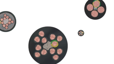
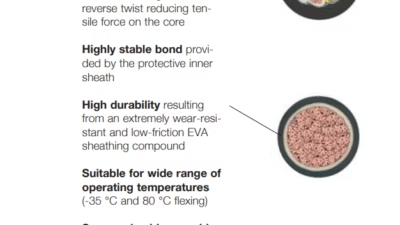
TXG-4 Rubber Round Cable – Heavy-Duty Highly Flexible Crane Festoon Cable with Advanced EMF Shielding
What is NGRDGOEU-J Cable?
TXG-4 Rubber Round Cable – Heavy-Duty Highly Flexible Crane Festoon Cable with Advanced EMF Shielding
Anhui Feichun Special Cable Co., Ltd. (安徽飞纯特种电缆有限公司)
NGRDGOEU-J cables, also known as TXG-4 rubber round cables, represent the pinnacle of heavy-duty crane festoon cable technology. Engineered for the most demanding industrial applications including container cranes, steel mills, foundries, and ship unloaders, these cables incorporate advanced features such as maximum EMF (Electromagnetic Field) prevention through braided outer shielding, pressure-filled extrusion for superior stability, and split earth conductor design for compact diameter. Unlike standard festoon cables, NGRDGOEU-J cables are specifically designed for environments with medium to high travel speeds (up to 250 m/min), frequent continuous bending, extreme temperature fluctuations, and the highest levels of atmospheric corrosion. This comprehensive technical guide provides engineers, procurement specialists, and maintenance professionals with the essential knowledge required for optimal specification and deployment of these premium industrial cables.
Table of Contents
- 1. Cable Overview and TXG-4 Designation
- 2. Purpose and Critical Applications
- 3. Advanced Characteristics and Features
- 4. Material Structure and Engineering Design
- 5. Compliance with International Standards
- 6. Electrical and Thermal Parameters
- 7. Safety Thresholds and Mechanical Ratings
- 8. Installation and Usage Precautions
- 9. Common Problems and Expert Solutions
- 10. Selection Guidelines and Comparisons
1. Cable Overview and TXG-4 Designation
The NGRDGOEU-J cable follows European cable nomenclature standards with specific designations that convey critical technical information about its construction and capabilities. The TXG-4 designation represents the cable’s classification within the heavy-duty festoon cable family.
Understanding the NGRDGOEU-J Code:
- N: Rubber insulated cable according to German standards
- G: Flexible conductor (fine-stranded for maximum flexibility)
- R: Rubber sheath (polychloroprene/PCP)
- D: Screen/shield (braided electromagnetic shielding)
- G: Common sheath around all cores
- O: Without protective conductor (for single-core configurations)
- E: Fine-stranded conductor Class 5 (high flexibility)
- U: Rated voltage 300/500V or 600/1,000V
- J: With green-yellow protective earth conductor
TXG-4 Classification Explained
The TXG-4 designation specifically identifies this cable as a Type 4 rubber round cable optimized for extreme duty festoon trolley applications. The “TXG” prefix denotes:
- T: Trolley system application
- X: Extra heavy-duty construction
- G: Gesamtabschirmung (German: total shielding/screening)
- 4: Performance class rating for maximum mechanical and environmental stress
This cable is engineered for applications where standard H07RN-F or even H07RN-8-F cables would fail prematurely due to excessive mechanical loads, high travel speeds, or severe environmental conditions.
2. Purpose and Critical Applications
Primary Purpose
NGRDGOEU-J cables are purpose-engineered for the most demanding mobile power transmission applications in heavy industry. Their primary purpose is to deliver reliable electrical power and control signals under conditions that would destroy conventional cables, including:
- Continuous high-speed movement with accelerations exceeding 1 m/s²
- Millions of bending cycles throughout the cable’s operational life
- Extreme temperature fluctuations from -35°C to +60°C
- Severe atmospheric corrosion in coastal, industrial, or chemical environments
- High electromagnetic interference requiring maximum EMF protection
- Heavy mechanical loads including tensile stress, compression, and torsion
Container Crane and Port Applications
Container Crane Trolley Power Supply
NGRDGOEU-J cables excel in container crane applications where trolleys must travel at speeds up to 250 m/min across long spans (often exceeding 50 meters) while handling massive containerized cargo. The cable’s braided EMF shielding prevents interference with automated crane control systems, while the pressure-filled extrusion maintains structural integrity under constant movement and vibration.
Typical Heavy-Duty Industrial Applications
Container Crane Trolleys
High-speed gantry crane power supply in seaports and intermodal terminals with maximum reliability requirements
Process Crane Trolleys
Manufacturing facility cranes handling raw materials, work-in-progress, and finished goods under continuous operation
Foundries and Steel Mills
Extreme environment cranes operating near molten metal with exposure to high temperatures and abrasive particulates
Stackers & Reclaimers
Bulk material handling systems in mining, coal yards, and storage facilities with 24/7 operation cycles
Ship Unloaders
Coastal crane systems exposed to salt spray, high humidity, and corrosive marine environments
Transport Carriers
Heavy-duty material transport systems requiring reliable power delivery across extensive travel distances
Secondary Application: Cable Reels
While primarily designed for festoon trolley systems, NGRDGOEU-J cables are also suitable for light-to-medium duty reeling applications where cables must be wound and unwound repeatedly. The cable’s excellent axial rigidity and resilience due to interlinked co-extruded sheaths provide the mechanical strength necessary for reeling operations, though specialized drum reeling cables may be preferred for heavy-duty reeling applications.
⚠ Application Limitation Note
For festoon applications, it is generally not recommended to use conductor cross-sections beyond 3×50mm² due to weight and flexibility considerations. For higher current requirements, consider using parallel cable runs or upgrading to specialized heavy-duty power distribution systems.
Reference: HELUKABEL – Crane & Hoisting Cable Systems
3. Advanced Characteristics and Features
Revolutionary EMF Shielding Technology
🛡️ Maximum Electromagnetic Field Prevention
NGRDGOEU-J cables incorporate a braided outer shield integrated into the cable sheath, providing superior EMF protection compared to conventional unshielded cables. This critical feature:
- Prevents EMI/RFI Interference: Protects sensitive control systems and automation equipment from electromagnetic interference generated by high-power conductors
- Reduces Signal Noise: Ensures clean, reliable transmission of control signals in mixed power/control cable installations
- Compliance with EMC Standards: Meets maximum emission values according to EN 55011/55022 for industrial environments
- Ground Path Integrity: Braided shield provides low-resistance ground path for fault current protection
- Protection from External Fields: Shields internal conductors from external electromagnetic interference sources
Pressure-Filled Extrusion Engineering
⚙️ Maximum Stability Within Stranded Bond
Unlike conventional cable manufacturing using loose lay-up methods, NGRDGOEU-J cables utilize pressure-filled extrusion (gusset-filling) technology that forces elastomeric filler material into all interstitial spaces within the cable assembly. Benefits include:
- Exceptional Structural Stability: Eliminates conductor movement within the cable, preventing mechanical fatigue
- Uniform Load Distribution: Pressure-filled design distributes mechanical stresses evenly across all conductors
- Enhanced Bend Radius Performance: Maintains consistent geometry during tight radius bending operations
- Improved Torsion Resistance: Resists twisting forces up to ±90°/m without conductor damage
- Water Sealing: Eliminates capillary pathways that could allow water ingress along conductor strands
Innovative Split Earth Conductor Design
Split Earth Conductor Technology
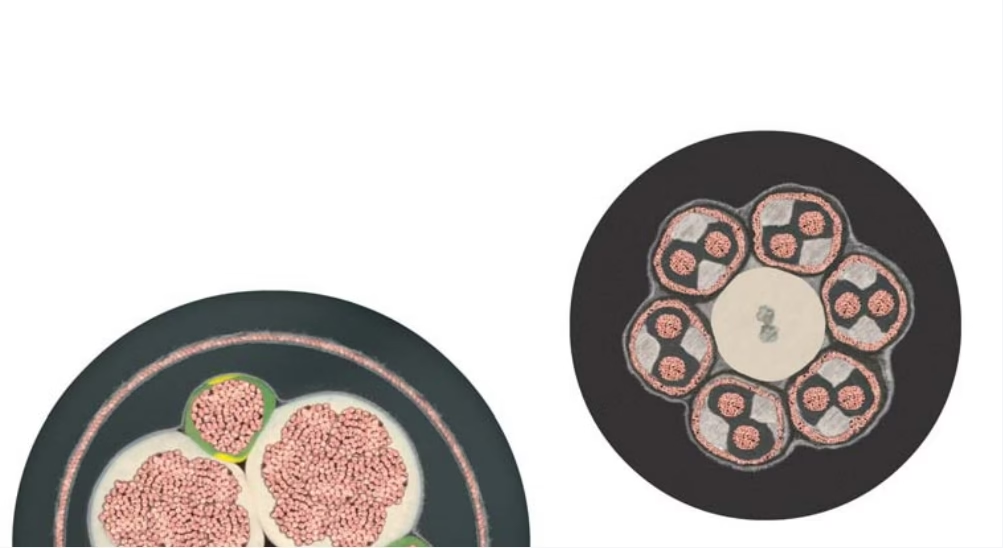
Power cables in the NGRDGOEU-J series utilize a unique split earth conductor design where the protective earth conductor is divided into three separate segments positioned symmetrically around the power conductors. This innovation delivers:
- Reduced Overall Diameter: Achieves 15-25% smaller cable diameter compared to conventional earth conductor arrangements
- Improved Flexibility: Smaller diameter directly translates to improved bending characteristics
- Weight Reduction: Lower cable weight reduces load on festoon trolley systems
- Maintained Safety: Combined cross-sectional area of split conductors meets protective earth requirements
- Balanced Structure: Symmetrical arrangement improves mechanical balance and reduces eccentric loading
Superior Material Performance
🌊 Humidity Resistance
Advanced elastomeric compounds provide complete resistance to humidity and moisture ingress, suitable for continuous operation in wet industrial environments and outdoor installations.
❄️ Extreme Low Temperature
Maintains flexibility and mechanical properties down to -35°C for flexing applications and -50°C for fixed installations – significantly better than standard cables.
☀️ UV Resistance
UV-stabilized polychloroprene sheath provides unlimited outdoor service life without degradation from ultraviolet radiation exposure.
🛢️ Oil Resistance
Polychloroprene (PCP) outer sheath offers excellent resistance to mineral oils, hydraulic fluids, and petroleum-based lubricants common in industrial environments.
☁️ Ozone Resistance
Specialized rubber formulations resist ozone-induced cracking and deterioration in high-voltage environments and areas with ozone-generating equipment.
🏭 Atmospheric Corrosion
Unlimited resistance to atmospheric corrosion enables deployment in harsh industrial atmospheres, coastal environments, and chemical processing facilities.
🔥 LBS-Free / Silicone-Free
Low Boiling Solvents (LBS) free formulation prevents environmental contamination; silicone-free construction prevents contamination in painting/coating processes.
💪 Wear-Resistant Sheathing
Specially compounded polychloroprene sheath provides exceptional abrasion resistance, extending service life in high-wear festoon applications.
Mechanical Excellence
Excellent Axial Rigidity and Resilience
The interlinked co-extruded sheath design creates a cable with exceptional axial rigidity (resistance to elongation under tension) while maintaining excellent resilience (ability to recover from deformation). This combination is achieved through:
- Co-Extruded Sheaths: Inner and outer sheaths are chemically bonded during extrusion for unified structure
- Optimized Shore Hardness: Carefully selected durometer ratings balance flexibility with mechanical strength
- Layered Stranding Structure: Conductors stranded in optimized layers for maximum flexibility with minimum diameter
- High Tensile Strength: Suitable for basic reeling applications requiring mechanical robustness
Complete Cable Family
The NGRDGOEU series offers a complete selection of cable types for comprehensive system solutions:
- Control Cables: 12-36 cores in 1.5mm² and 2.5mm² cross-sections for complex control systems
- Power Cables (Single-Core): 35mm² to 185mm² for high-current single-phase or DC applications
- Power Cables (Multi-Core): 4-core and 5-core configurations from 4mm² to 50mm² for three-phase power distribution
- Screened Power Bundles: Individually shielded conductor groups for maximum EMC performance
- Bus Cables: Screened twisted-pair configurations for fieldbus and data communication
- Optical Fiber Cables: Integrated fiber optic solutions for data transmission alongside power
Reference: igus – Flexible Cables for Crane Industry
4. Material Structure and Engineering Design
Conductor Engineering
The foundation of NGRDGOEU-J cable performance lies in its sophisticated conductor design:
Conductor Specifications
- Material: Bare electrolytic copper (>99.9% purity) conforming to DIN VDE 0295 Class 5
- Flexibility Class: Class 5 according to DIN VDE 0295 and IEC 60228 (highest flexibility for fixed installation cables)
- Stranding: Multiple fine wire strands (0.2-0.3mm diameter) arranged in concentric layers with optimized lay length
- Strand Count: Significantly higher than standard cables for enhanced flexibility and fatigue resistance
- Conductor Diameter Tolerance: Tight manufacturing tolerances ensure consistent electrical and mechanical properties
- Surface Finish: Bright-annealed copper for optimal conductivity and flexibility
Core Insulation System
Each conductor is individually insulated with resilient Ethylene-Propylene-Rubber (EPR):
EPR Insulation Characteristics
- Material Type: Resilient EPR (Ethylene-Propylene-Rubber) compound with superior elastic properties
- Dielectric Strength: Exceeds minimum requirements for 600/1,000V rated voltage with safety margin
- Flexibility Retention: Maintains elasticity across full temperature range (-35°C to +60°C flexing)
- Chemical Resistance: Resistant to oils, mild acids, alkalis, and industrial chemicals
- Mechanical Resilience: Exceptional resistance to compression and abrasion from continuous flexing
- Insulation Thickness: Optimized for voltage rating and mechanical protection per IEC standards
Cable Assembly and Pressure Filling
The unique assembly process differentiates NGRDGOEU-J from standard cables:
- Layer Stranding: Insulated conductors are stranded in layers around a stable tension-proof center element
- Bundle Formation: For cables with 12+ cores, bundle stranding method groups conductors into sub-assemblies
- Pressure Filling: Elastomeric filler compound is extruded under pressure to fill all voids between conductors
- Inner Jacket Application: First polychloroprene layer is applied over the filled core assembly
- Shield Integration: Braided copper shield (typically 85%+ optical coverage) is applied over inner jacket
- Outer Sheath Extrusion: Final wear-resistant PCP layer encapsulates the entire assembly
Braided EMF Shield Construction
Shield Design Specifications
- Shield Material: Tinned copper wire (0.15-0.20mm diameter) for optimal conductivity and oxidation resistance
- Braid Pattern: Optimized braiding angle (typically 30-45°) balances EMF shielding with flexibility
- Coverage Factor: Minimum 85% optical coverage; up to 95% for enhanced EMC applications
- Attenuation Performance: Provides >40dB shielding effectiveness across broad frequency spectrum
- Ground Continuity: Low DC resistance (typically <5 mΩ/m) ensures effective fault current path
- Mechanical Support: Tight braid construction provides torsion protection and mechanical reinforcement
Polychloroprene (PCP) Outer Sheath
The wear-resistant outer sheath provides comprehensive environmental protection:
| Property | Specification | Benefit |
|---|---|---|
| Base Material | Polychloroprene (Neoprene) CR | Balanced oil, ozone, and weather resistance |
| Shore Hardness | 65-75 Shore A (typical) | Optimal balance of flexibility and abrasion resistance |
| Tensile Strength | >10 N/mm² | High mechanical strength for demanding applications |
| Elongation at Break | >300% | Excellent resilience and flexibility retention |
| Abrasion Resistance | Enhanced formulation | Extended service life in high-wear environments |
| Color | Black (standard) | UV stability and professional appearance |
Core Identification System
Conductor identification follows DIN VDE 0293 part 308 color coding standards with enhanced visibility:
| Cable Type | Core Count | Color Identification |
|---|---|---|
| Control Cables | Up to 5 cores | Standard colors: Brown, Blue, Black, Grey, Green/Yellow |
| Control Cables | 6+ cores | Black with white numbered printing + Green/Yellow earth |
| Power 4-Core | 4G configuration | Brown, Black, Grey (or Blue), Green/Yellow |
| Power 5-Core | 5G configuration | Brown, Black, Grey, Blue, Green/Yellow |
| Screened Power | 3x + 3G earth | Split earth conductors in green/yellow grouped with power phases |
Interlinked Co-Extruded Sheath Technology
Advanced Manufacturing Process
The “interlinked co-extruded sheaths” represent a sophisticated manufacturing technology where multiple elastomeric layers are applied simultaneously and chemically bond during the curing process. This creates a monolithic structure with:
- Delamination Resistance: Layers cannot separate under mechanical stress
- Enhanced Mechanical Properties: Combined structure is stronger than sum of individual layers
- Improved Water Blocking: No interface pathways for moisture migration
- Superior Flex Life: Unified structure eliminates interlayer friction during bending
Reference: DG Crane – Overhead Crane Cable Construction Standards
5. Compliance with International Standards
Primary Manufacturing Standards
NGRDGOEU-J cables are manufactured in accordance with comprehensive international and national standards:
| Standard | Description | Scope |
|---|---|---|
| DIN VDE 0282 | German standard for rubber insulated cables | Cable construction, materials, dimensions, and testing requirements |
| DIN VDE 0295 | Conductor classification standard | Defines Class 5 flexibility, stranding requirements, and resistance values |
| DIN VDE 0298-3 | Use of cables in power installations | Tensile load-bearing capacity of 15 N/mm² during operation for moving cables |
| DIN VDE 0293-308 | Core identification standards | Color coding and identification of insulated conductors |
| IEC 60228 | International conductor standard | Conductor materials, stranding classes, and electrical resistance |
| IEC 60364-5-52 | Electrical installations standard | Selection and erection of electrical equipment – wiring systems |
EMC and Shielding Standards
Electromagnetic Compatibility Compliance
The braided shield in NGRDGOEU-J cables provides EMC performance meeting or exceeding:
- EN 55011: Industrial, scientific and medical equipment – Radio-frequency disturbance characteristics – Limits and methods of measurement
- EN 55022: Information technology equipment – Radio disturbance characteristics – Limits and methods of measurement
- IEC 61000 Series: Electromagnetic compatibility standards for industrial environments
- Shielding Effectiveness: Typically >40dB attenuation from 10 kHz to 1 GHz frequency range
Mechanical and Environmental Standards
- DIN VDE 0298-4: Current-carrying capacity and permissible conductor temperatures
- IEC 60332-1: Tests on electric cables under fire conditions – vertical flame propagation test
- VDE 0472-803: Testing of cables and insulated cords – behavior of cables in fire (corresponds to IEC 60332-1)
- EN 60811 Series: Insulation and sheathing materials – common test methods (physical, mechanical, thermal tests)
Application-Specific Guidelines
Crane and Festoon System Standards
- FEM 9.511: European Federation of Material Handling – Rules for festoon systems
- DIN 15018: Cranes – Principles for steel structures – Calculation
- ISO 4301: Cranes – Classification standards
- EN 13001 Series: Crane safety – General design principles
- CMAA Specification #70: Specifications for electric overhead traveling cranes (North American)
Safety and Environmental Certifications
Compliance Certifications
- CE Marking: Compliance with European Union safety and environmental directives
- RoHS Compliance: Restriction of Hazardous Substances – lead-free and environmentally friendly materials
- REACH Compliance: European chemicals regulation – no substances of very high concern (SVHC)
- LBS-Free Certification: Low Boiling Solvents free formulation
- Silicone-Free: Prevents contamination in paint shops and coating facilities
- ISO 9001: Quality management system certification for manufacturing processes
Testing and Verification Requirements
NGRDGOEU-J cables undergo comprehensive type testing and routine production testing:
| Test Category | Test Parameters | Acceptance Criteria |
|---|---|---|
| Electrical Tests | High voltage test, conductor resistance, insulation resistance | Per IEC 60502 and VDE specifications |
| Mechanical Tests | Tensile strength, elongation, abrasion resistance, bending cycles | Minimum 1 million flex cycles at 5× diameter bend radius |
| Environmental Tests | Temperature cycling, ozone resistance, oil immersion, UV exposure | No visible cracking or property degradation |
| EMC Tests | Shielding effectiveness, transfer impedance, attenuation | >40dB shielding across specified frequency range |
| Fire Tests | Vertical flame test, smoke density, halogen content | Self-extinguishing per IEC 60332-1 |
Reference: IEC Webstore – International Electrotechnical Standards
6. Electrical and Thermal Parameters
Voltage Ratings
| Parameter | Value | Application Notes |
|---|---|---|
| Rated Voltage (Uo/U) | 600/1,000 V AC | Standard rating (Uo = phase-to-ground, U = phase-to-phase) |
| Lower Voltage Rating | 300/500 V AC | Available for control cable variants (NGRDGOU series) |
| DC Voltage Rating | 750/1,500 V DC | For DC traction and drive applications |
| Test Voltage (AC) | 3.5 kV | Factory type test voltage – 5 minutes duration |
| Impulse Voltage | 8 kV (1.2/50 μs) | Lightning and switching surge withstand capability |
Current-Carrying Capacity (Ampacity)
Reference Conditions for Ampacity Ratings
- Ambient Temperature: 30°C (standard reference)
- Installation Method: Individual free cabling in air (no bundling or contact with other cables)
- Conductor Operating Temperature: 60°C continuous (90°C permissible for limited periods)
- Duty Cycle: 100% continuous operation at rated load
- Derating Factors: Must be applied for elevated ambient temperatures, bundled cables, enclosed installations
Sample Ampacity Values (Based on Tables)
| Cable Configuration | Conductor Size | Ampacity (A) | Weight (kg/100m) |
|---|---|---|---|
| Control Cable | 12G 1.5 | 10.0 | 44.0 |
| Control Cable | 24G 2.5 | 11.4 | 111.0 |
| Power Cable 1-core | 1×70 | 257.3 | 83.5 |
| Power Cable 1-core | 1×185 | 470.4 | 201.0 |
| Power Cable 4-core | 4G 16 | 86.1 | 107.0 |
| Power Cable 5-core | 5G 25 | 96.3 | 194.0 |
⚠ Critical Ampacity Considerations
Actual current-carrying capacity varies significantly based on:
- Festoon System Configuration: Cables in festoon systems may have reduced ampacity due to limited air circulation
- Travel Speed and Duty Cycle: High-speed operation and frequent starting/stopping increases conductor temperature
- Ambient Temperature: For every 10°C increase above 30°C, derate by approximately 10-15%
- Grouping Factor: Multiple cables in close proximity require additional derating
- Solar Radiation: Outdoor installations under direct sunlight require additional derating consideration
Temperature Ratings
| Condition | Temperature Range | Application |
|---|---|---|
| Ambient – Flexing | -35°C to +60°C | Continuous movement applications (festoon systems, cable reels) |
| Ambient – Fixed Installation | -50°C to +80°C | Stationary installations with no mechanical movement |
| Maximum Conductor Temp | +60°C (normal) +90°C (emergency) | Continuous operation / Short-term overload conditions |
| Short-Circuit Temperature | +200°C | Maximum conductor temperature during fault (5 seconds max) |
| Installation Temperature | -10°C minimum | Minimum ambient temperature for cable installation/handling |
Electrical Resistance and Impedance
Conductor DC Resistance (at 20°C)
Maximum conductor resistance values per DIN VDE 0295 for copper conductors:
- 1.5mm²: ≤13.3 Ω/km
- 2.5mm²: ≤7.98 Ω/km
- 4mm²: ≤4.95 Ω/km
- 10mm²: ≤1.91 Ω/km
- 25mm²: ≤0.780 Ω/km
- 50mm²: ≤0.387 Ω/km
- 95mm²: ≤0.206 Ω/km
- 185mm²: ≤0.106 Ω/km
Insulation Resistance and Dielectric Properties
| Parameter | Specification | Test Method |
|---|---|---|
| Insulation Resistance | >20 MΩ·km at 20°C | Measured at 500V DC after 1 minute |
| Dielectric Strength | 3.5 kV AC for 5 minutes | Type test on completed cable |
| Partial Discharge | <10 pC at 1.2× rated voltage | Quality control test for medium voltage variants |
| Capacitance | ~0.3-0.5 μF/km | Depends on conductor configuration and size |
Voltage Drop Calculations
Voltage Drop Considerations
For accurate voltage drop calculations in festoon systems:
- Total Cable Length: Must include full festoon loop length (115-120% of travel distance)
- Resistance Temperature Coefficient: Copper resistance increases 0.393% per °C
- Inductance: For conductors >16mm², inductive reactance becomes significant
- Power Factor: Actual system power factor affects voltage drop calculations
- Typical Voltage Drop Limit: 3-5% for power circuits, 1-2% for sensitive control circuits
Reference: Eland Cables – GRDGOU Technical Parameters
7. Safety Thresholds and Mechanical Ratings
Mechanical Load-Bearing Capacity
NGRDGOEU-J cables are engineered to withstand extreme mechanical loads far exceeding standard festoon cables:
| Parameter | Specification | Notes |
|---|---|---|
| Maximum Travel Speed | Up to 250 m/min | From 210 m/min requires motorized festoon systems with cable guidance |
| Acceleration | Up to 2.0 m/s² | Significantly higher than standard cables (typically 0.8 m/s² limit) |
| Minimum Bending Radius – Dynamic | 5 × Cable Outer Diameter | For continuous flexing with free movement in festoon systems |
| Minimum Bending Radius – Fiber Optic | 125 mm (absolute minimum) | Special requirement for optical fiber cable variants |
| Tensile Load During Operation | 15 N/mm² | Maximum permitted tensile stress on conductor cross-section per DIN VDE 0298-3 |
| Torsional Stress | ±90°/m | Maximum twist angle per meter of cable length |
Permitted Tensile Loads by Configuration
Maximum Pulling Forces
The cable structure is designed to withstand specific pulling forces during installation and operation:
Control Cables:- 12G 1.5: 270 N
- 24G 1.5: 540 N
- 12G 2.5: 450 N
- 36G 2.5: 1,350 N
- 1×35: 525 N
- 1×70: 1,050 N
- 1×120: 1,800 N
- 1×185: 2,775 N
- 4G 10: 600 N
- 4G 25: 1,500 N
- 4G 50: 3,000 N
- 5G 25: 1,875 N
Flex Cycle Life and Durability
Extended Service Life Performance
NGRDGOEU-J cables are designed for exceptional durability:
- Minimum Flex Cycles: >1,000,000 full bending cycles at rated bending radius
- High-Duty Cycle Performance: Suitable for continuous operation with frequent starting/stopping
- Vibration Resistance: Withstands crane structure vibration and wind-induced cable movement
- Abrasion Resistance: Wear-resistant sheath compound extends service life in high-wear environments
- Expected Service Life: 8-12 years typical in heavy-duty festoon applications (vs. 3-5 years for standard cables)
Environmental Safety Limits
| Environmental Factor | Safety Threshold | Performance Rating |
|---|---|---|
| UV Exposure | Unlimited outdoor exposure | UV-stabilized PCP sheath – no degradation |
| Ozone Concentration | Resistant to all normal ozone levels | Suitable for high-voltage environments |
| Humidity | 0-100% relative humidity | Fully waterproof construction |
| Oil/Grease Exposure | Continuous immersion acceptable | Resistant to mineral oils and hydraulic fluids |
| Atmospheric Corrosion | Unlimited resistance | Suitable for coastal and industrial atmospheres |
| Salt Spray | Per ISO 9227 (>1000 hours) | Marine environment rated |
Electrical Safety Thresholds
⚠ Critical Electrical Safety Requirements
- Maximum Operating Voltage: Never exceed 1,000V AC (1,500V DC) rated voltage
- Earth Continuity: Verify protective earth (green/yellow) continuity <0.1Ω end-to-end before operation
- Shield Grounding: Braided EMF shield must be properly grounded at one or both ends per EMC requirements
- Short Circuit Protection: Install circuit breakers or fuses rated appropriately for cable ampacity
- Residual Current Devices: Consider RCD protection for personnel safety in mobile applications
- Periodic Testing: Perform annual insulation resistance testing (minimum 1 MΩ acceptance)
- Fault Current Rating: Verify cable can safely carry maximum prospective fault current for specified duration
Fire Safety Performance
Fire-Related Safety Features
- Flame Propagation: Self-extinguishing per IEC 60332-1 vertical flame test
- Smoke Generation: Moderate smoke density (not low-smoke or LSZH rated)
- Halogen Content: Contains chlorine from polychloroprene – NOT halogen-free
- Corrosive Gases: Will produce HCl gas during combustion – ensure adequate ventilation
- Fire Load: Consider cable mass in building fire load calculations
- Special Applications: For tunnels, public buildings, or ships requiring LSZH cables, specify alternative cable types
Installation Safety Margins
⚠ Safety Factors for Mechanical Design
- Bending Radius Safety Factor: Use 6-8× diameter for festoon design (vs. 5× minimum)
- Tensile Load Safety Factor: Design for 50% of maximum permitted tensile load under normal operation
- Temperature Derating: If ambient >45°C, consider forced ventilation or cable upsizing
- Acceleration Limits: Design festoon system for 80% of maximum cable-rated acceleration
- Cable Weight Consideration: Account for cable weight in festoon trolley and track design
Reference: Tullyn Trading – Rondoflex NGRDGOEU Technical Data
8. Installation and Usage Precautions
Pre-Installation Inspection and Planning
Critical Pre-Installation Checks
- Cable Inspection: Visually inspect entire cable length for damage, proper marking, and specification match
- Shield Verification: Verify braided shield is present and properly integrated (critical for EMF protection)
- Conductor Verification: Confirm conductor configuration, count, and cross-sections match specifications
- Length Calculation: For festoon systems, cable length must be 115-120% of travel distance for proper loop formation
- Environmental Assessment: Verify installation environment is within cable temperature and chemical compatibility ratings
- Load Analysis: Calculate actual ampacity requirements including derating factors
- Mechanical Design Review: Confirm bending radii, tensile loads, and accelerations are within cable ratings
Storage and Handling
- Storage Temperature: Store cables at 0°C to +35°C in dry, ventilated warehouse
- Reel Orientation: Store reels vertically to prevent cable deformation; rotate reels quarterly if stored >6 months
- UV Protection: Although cable is UV-resistant, protect reels from prolonged direct sunlight during storage
- Moisture Protection: Seal cable ends with heat-shrink caps to prevent moisture ingress
- Handling Equipment: Use proper reel handling equipment rated for cable weight (cables can exceed 200 kg/100m)
- Minimum Handling Radius: During unreeling, maintain 8× diameter minimum bend radius to prevent damage
- Installation Temperature: Do not install cables when ambient temperature is below -10°C
Motorized Festoon System Requirements
High-Speed Festoon Installation (>210 m/min)
For travel speeds exceeding 210 m/min, motorized festoon systems with active cable guidance are mandatory:
- Cable Guidance System: Install positive cable guidance to prevent cable swing and collision
- Trolley Spacing: Reduce trolley spacing to 1.0-1.5m intervals (vs. 2-3m for standard festoon)
- Motorized Drive: Use motorized trolley system synchronized with crane travel
- Acceleration Limiting: Implement soft-start controls to limit acceleration to <1.5 m/s²
- End Position Monitoring: Install end-of-travel sensors to prevent cable over-extension
- Tension Monitoring: Consider load cells or tension monitoring for critical applications
Braided Shield Grounding
EMF Shield Termination Requirements
Proper grounding of the braided shield is critical for EMF protection:
- Single-End Grounding: For cable runs <50m, ground shield at source end only to prevent ground loops
- Both-Ends Grounding: For cable runs >50m or high-frequency applications, ground at both ends
- Ground Connection: Use 360° shield termination with proper cable glands or shield clamps
- Ground Path Resistance: Verify shield-to-ground resistance is <0.1Ω for effective EMF protection
- Isolation Testing: Confirm shield is isolated from conductors (>1 MΩ shield-to-conductor resistance)
- Festoon Track Bonding: Ensure festoon track system is properly grounded and bonded
Termination Best Practices
Professional Termination Procedures
- Cable Preparation: Remove outer sheath using rotary cable stripper (avoid blade damage to shield braid)
- Shield Termination: Carefully fold back shield braid and secure with shield gland or tape
- Conductor Stripping: Strip individual conductor insulation to minimum required length (10-12mm typical)
- Ferrule Installation: Use properly sized compression ferrules for all conductor terminations
- Crimping Quality: Use calibrated crimping tools; verify crimp quality by pull-test sampling
- Terminal Torque: Tighten terminal screws to manufacturer-specified torque values (use torque wrench)
- Strain Relief: Install proper strain relief devices rated for cable diameter and weight
- Sealing: Use cable glands with appropriate IP rating for environment (minimum IP54 for festoon systems)
- Identification: Mark all terminations with cable identification and circuit designations
Operational Precautions
⚠ Critical Operational Safety Rules
- Load Monitoring: Implement current monitoring on power cables; alarm at 90% rated ampacity
- Temperature Monitoring: For critical applications, install temperature sensors on high-current conductors
- Visual Inspections: Conduct weekly visual inspections of cable and festoon system
- Movement Clearances: Maintain minimum 50mm clearance between cable and all stationary structures
- Cable Sag Management: Adjust festoon system if excessive cable sag is observed
- Vibration Damping: Install vibration dampers if cable vibration is excessive in high-wind environments
- Emergency Stop: Ensure emergency stop systems immediately halt crane movement in case of cable entanglement
Festoon System-Specific Installation
| Component | Installation Requirement | Critical Check Points |
|---|---|---|
| Festoon Track | Alignment within ±5mm over full length | Straightness, joint quality, mounting security |
| Cable Trolleys | Free rolling with <5N rolling resistance per trolley | Bearing condition, wheel alignment, saddle integrity |
| Cable Loops | Form natural catenary with minimum sag | Loop symmetry, uniform cable distribution, no twisting |
| End Clamps | Secure cable without deformation | Proper clamping force, strain relief, no sharp edges |
| Towing Trolley | Smooth travel across full crane stroke | Connection security, no cable twisting at attachment |
Maintenance Schedule
| Frequency | Maintenance Activity | Action Items |
|---|---|---|
| Weekly | Visual Inspection | Check for visible damage, abrasion, proper cable routing, trolley operation |
| Monthly | Detailed Cable Inspection | Examine full cable length, check terminations, verify clearances |
| Quarterly | Festoon System Service | Clean tracks, inspect trolley bearings, check cable tension, verify alignment |
| Semi-Annually | Electrical Testing | Insulation resistance, earth continuity, shield continuity, load testing |
| Annually | Comprehensive Assessment | Full electrical testing, thermal imaging, flex life evaluation, replacement planning |
⚠ NEVER Perform These Actions
- Install with bending radius less than 5× cable diameter
- Exceed travel speeds of 250 m/min or accelerations of 2.0 m/s²
- Operate cable outside temperature range (-35°C to +60°C flexing)
- Allow cable contact with sharp edges, abrasive surfaces, or moving machinery
- Ground both ends of shield in short cable runs (may cause ground loops)
- Splice cables in festoon applications (use proper junction boxes if necessary)
- Use damaged cables or cables with compromised braided shield
- Exceed maximum conductor cross-section of 3×50mm² in festoon applications
- Install cables near heat sources exceeding 60°C
Reference: Hybird Resources – NGRDGOEU Installation Guidelines
9. Common Problems and Expert Solutions
Shield-Related Issues
Problem: EMI Interference Despite Shielded Cable
Causes:
- Shield not properly grounded or grounded at wrong locations
- Shield damaged during installation or operation
- Insufficient shield coverage due to manufacturing defect
- Ground loops causing shield current flow
Solutions:
- Verify 360° shield termination at both cable ends using proper shield glands
- Test shield continuity (should be <0.1Ω end-to-end)
- For cable runs <50m, ground shield at source end only to eliminate ground loops
- Inspect shield for physical damage; replace cable section if shield is compromised
- Verify shield-to-conductor isolation is >1 MΩ
- Use RF spectrum analyzer to identify interference frequencies and sources
High-Speed Operation Problems
Problem: Cable Damage at Travel Speeds >200 m/min
Causes:
- Excessive cable vibration and whipping at high speeds
- Insufficient cable guidance in motorized festoon system
- Trolley spacing too wide causing excessive cable sag and swing
- High acceleration rates causing shock loading on cable
Solutions:
- Install active cable guidance system with positive position control
- Reduce trolley spacing to 1.0-1.5m intervals for high-speed applications
- Implement soft-start/soft-stop controls to limit acceleration to <1.5 m/s²
- Add intermediate cable support points or use motorized trolley system
- Install wind shields or cable enclosures in high-wind outdoor environments
- Consider upgrading to specialized high-speed festoon cable if speeds consistently exceed 230 m/min
Mechanical Failure Modes
Problem: Conductor Strand Breakage and Fatigue
Causes:
- Bending radius too small for cable construction
- Excessive tensile load during operation or installation
- Cable exceeded designed flex cycle life
- Vibration fatigue at termination points
- Torsional stress beyond ±90°/m specification
Solutions:
- Measure actual bending radii and adjust festoon system geometry to achieve 6-8× diameter
- Install proper strain relief devices at all termination points
- Implement predictive maintenance program tracking flex cycles and cable condition
- Use vibration-damping cable glands at fixed termination points
- Verify cable routing prevents twisting; install anti-rotation devices if necessary
- If fatigue failure is premature, investigate for installation errors or overload conditions
Temperature-Related Problems
Problem: Cable Overheating or Thermal Damage
Causes:
- Conductor undersized for actual load current
- Inadequate derating for ambient temperature or cable grouping
- Poor termination connections causing resistive heating
- Excessive duty cycle or insufficient rest periods
- Cable damaged internally reducing effective conductor cross-section
Solutions:
- Perform thermal imaging survey to identify hot spots
- Measure actual load currents and compare to derated ampacity values
- Inspect and remake all termination connections; verify proper torque and ferrule crimping
- If ambient temperature exceeds 45°C, consider forced ventilation or cable upsizing
- Implement load management to reduce duty cycle or install larger conductor cross-section
- Test conductor resistance end-to-end to detect internal damage
Environmental Damage
Problem: Premature Sheath Deterioration
Causes:
- Exposure to incompatible chemicals (strong acids, organic solvents)
- Abrasion from contact with sharp edges or contaminated festoon tracks
- Substandard cable not meeting true NGRDGOEU-J specifications
- UV degradation from prolonged storage before installation
Solutions:
- Perform chemical compatibility testing before installation in chemical processing areas
- Install cable protective channels or shields at points of potential abrasion
- Verify cable authenticity: Demand manufacturer test certificates and verify cable marking includes proper NGRDGOEU-J designation
- Inspect festoon tracks for sharp edges, burrs, or debris that could damage cable sheath
- For aggressive chemical environments, consider upgrading to PUR-sheathed cable alternatives
Festoon System Operational Issues
Problem: Trolley Jamming, Binding, or Uneven Cable Distribution
Causes:
- Festoon track misalignment or damage
- Trolley bearing failure or wheel damage
- Debris or contamination in track channels
- Cable twist causing binding in trolley saddles
- Uneven cable weight distribution across trolleys
Solutions:
- Survey festoon track alignment using laser alignment tools; realign to within ±5mm tolerance
- Replace worn or damaged trolley assemblies; upgrade to sealed bearing trolleys in dusty environments
- Implement regular track cleaning schedule; install track covers in severely contaminated areas
- Verify cable routing does not introduce twist; install cable straighteners at entry/exit points
- Balance cable load by adjusting trolley positions and ensuring even cable distribution in loops
- Consider upgrading to motorized festoon system for improved reliability
Installation Errors
⚠ Critical Installation Mistakes to Avoid
- Incorrect Voltage Selection: Using 300/500V cable where 600/1,000V rating is required
- Shield Not Terminated: Failing to properly ground braided shield eliminates EMF protection
- Inadequate Cable Length: Not allowing 115-120% of travel distance for festoon loop formation
- Wrong Cable Type: Specifying standard H07RN-F where NGRDGOEU-J is required for high-speed/high-stress application
- Conductor Cross-Section Too Large: Exceeding 3×50mm² in festoon applications causes excessive weight and flexibility problems
- Missing Split Earth Conductor: For screened power cables, verify split earth conductor configuration is correct
- Poor Strain Relief: Inadequate strain relief at terminations causes premature conductor fatigue
Diagnostic Procedures
Systematic Troubleshooting Approach
- Visual Inspection: Examine full cable length for physical damage, abrasion, or environmental deterioration
- Electrical Testing:
- Insulation resistance test: Conductor-to-conductor and conductor-to-shield (>1 MΩ acceptable, >10 MΩ good)
- Earth continuity: <0.5Ω for protective earth conductor
- Shield continuity: <0.1Ω for braided shield ground path
- Conductor resistance: Compare to manufacturer specifications for evidence of internal damage
- Thermal Imaging: Infrared survey under load to identify overheating connections or conductors
- Mechanical Assessment:
- Measure actual bending radii at all points in festoon system
- Check trolley operation and track condition
- Verify clearances and inspect for collision damage
- Assess cable flexibility and check for stiffness indicating internal damage
- EMC Testing: If interference issues persist, use spectrum analyzer and near-field probes to characterize EMI sources
- Load Analysis: Measure actual current draw and compare to ampacity ratings with appropriate derating
10. Cable Selection Guidelines and Comparisons
When to Specify NGRDGOEU-J Cable
✓ Ideal Applications for NGRDGOEU-J / TXG-4
NGRDGOEU-J cables are the optimal choice when your application includes these characteristics:
- Medium to High Travel Speeds: Trolley/crane speeds from 120 m/min up to 250 m/min
- High Duty Cycle: Frequent and continuous bending with millions of flex cycles required
- Robust and Durable Priority: Application demands highest possible reliability and longest service life
- Very High Atmospheric Corrosion: Harsh industrial, coastal, or chemical processing environments
- Extended Temperature Range: Operating temperatures from -35°C to +60°C in flexing applications
- EMF Shielding Required: Sensitive control systems or compliance with EMC standards EN 55011/55022
- High Mechanical Loads: Acceleration >1 m/s² and tensile loads approaching maximum ratings
- Compact Installation: Limited space requiring smallest possible cable diameter (split earth conductor benefit)
NGRDGOEU-J vs. H07RN-F Comparison
| Feature | NGRDGOEU-J (TXG-4) | H07RN-F (Standard) |
|---|---|---|
| Rated Voltage | 600/1,000V | 450/750V |
| EMF Shielding | Braided shield integrated | No shielding |
| Construction Method | Pressure-filled extrusion | Standard lay-up |
| Earth Conductor | Split earth (3-part) for power cables | Single integrated earth conductor |
| Maximum Travel Speed | 250 m/min | 120 m/min |
| Temperature Range (Flexing) | -35°C to +60°C | -30°C to +60°C |
| Typical Flex Life | >1,000,000 cycles | ~500,000 cycles |
| Application | Heavy-duty industrial cranes | General festoon, light-medium duty |
| Relative Cost | Premium (100-150% more) | Standard baseline |
Cable Selection Decision Tree
Quick Selection Guide
Use NGRDGOEU-J when:
- Container cranes, ship unloaders, or large gantry cranes
- Travel speeds >120 m/min or acceleration >1 m/s²
- Foundries, steel mills, or extreme corrosion environments
- EMC compliance required or sensitive electronics present
- Application critical with zero-tolerance for cable failure
- 24/7 operation with high duty cycle
Use H07RN-F when:
- General indoor manufacturing or warehouse cranes
- Travel speeds <120 m/min with moderate duty cycle
- Standard industrial environment without severe corrosion
- Cost optimization is priority with acceptable service life
- Small to medium single-plane dynamic loads
Configuration Selection Guidelines
| Application Type | Recommended NGRDGOEU-J Configuration | Typical Sizes |
|---|---|---|
| Complex Control Systems | Control cables 12-36 cores | 12G1.5, 18G1.5, 24G2.5, 36G2.5 |
| Three-Phase Power (Low) | 4-core or 5-core power cables | 4G6, 5G6, 4G10, 5G10 |
| Three-Phase Power (Medium) | 4-core or 5-core power cables | 4G16, 5G16, 4G25, 5G25 |
| High-Current Single Phase/DC | Single-core cables in parallel | 1×70, 1×95, 1×120, 1×185 |
| Maximum EMC Performance | Screened power bundles (NGRDGCG series) | 4G10C, 4G16C, 4G25C |
| Fieldbus/Data Communication | Bus cables screened in pairs | 6×(2×0.5)C, 6×(2×1)C, 9×(2×1)C |
| Integrated Data + Power | Optical fiber cables | 6G 62.5/125, 18G 50/125 |
Sizing Considerations
Critical Sizing Parameters
- Ampacity Derating: For festoon applications, derate ampacity by 15-25% due to limited air circulation
- Voltage Drop: Calculate using 115-120% of travel distance as effective cable length
- Weight Limitation: For festoon systems, total cable weight should not exceed festoon track and trolley ratings
- Maximum Cross-Section: Practical limit of 3×50mm² for festoon applications due to weight and flexibility
- Future Expansion: Consider upsizing conductors by one standard size for future load growth
- Parallel Runs: For very high currents, use multiple parallel cables rather than single oversized cable
Quality Verification
⚠ Ensuring Authentic NGRDGOEU-J Quality
Due to the premium nature of NGRDGOEU-J cables, verify quality through:
- Manufacturer Certification: ISO 9001 quality management and ISO 14001 environmental certification
- Cable Marking: Continuous printing on sheath must include “NGRDGOEU-J” or “NGRDGOEU-O” designation
- Test Certificates: Demand factory test certificates for electrical tests, shield continuity, and mechanical properties
- Shield Verification: Visually verify braided shield is present during cable end preparation
- Weight Check: Verify cable weight matches specifications (pressure filling adds significant weight)
- Physical Inspection: Cut sample and verify pressure-filled construction, split earth conductor (for power cables)
- Reputable Suppliers: Source from established manufacturers like Prysmian (Rondoflex brand) or equivalent
Economic Analysis
Total Cost of Ownership
While NGRDGOEU-J cables cost 100-150% more than standard H07RN-F cables initially, the total cost of ownership is often lower due to:
- Extended Service Life: 8-12 years vs. 3-5 years for standard cables (2-3× longer life)
- Reduced Downtime: Higher reliability means fewer unplanned outages and production losses
- Lower Maintenance: Fewer inspections and replacements reduce maintenance labor costs
- EMC Compliance: Integrated shielding eliminates need for separate EMC mitigation measures
- Critical Applications: For mission-critical cranes where downtime costs are extremely high, premium cables offer excellent ROI
Procurement Specifications
When preparing procurement documents for NGRDGOEU-J cables, include:
- Cable type designation: NGRDGOEU-J per DIN VDE 0282 (or NGRDGOEU-O for single-core)
- Rated voltage: 600/1,000V (or 300/500V for control cable variants)
- Number of cores and conductor cross-section (e.g., 5G16, 24G2.5, 1×120)
- Required cable lengths and cutting tolerance
- Packaging requirements: reels (preferred for festoon applications)
- Test certificates required: electrical tests, shield continuity, mechanical properties
- EMC performance specification: Shielding effectiveness >40dB, EN 55011/55022 compliance
- Manufacturer certifications: ISO 9001, RoHS, REACH compliance
- Delivery schedule and storage requirements
- Warranty period: Typically 24-36 months from delivery
Reference: Hybird Resources – NGRDGOEU Cable Selection Guide
Conclusion
The NGRDGOEU-J Type TXG-4 rubber round cable represents the premium solution for heavy-duty crane festoon systems operating under the most demanding industrial conditions. Its advanced features—including integrated EMF shielding, pressure-filled extrusion for maximum stability, split earth conductor design for compact diameter, and exceptional environmental resistance—make it the cable of choice for container cranes, steel mills, foundries, and other extreme-duty applications where standard cables would fail prematurely.
For engineers and maintenance professionals working with high-speed overhead cranes, gantry systems, and material handling equipment in harsh industrial environments, understanding the comprehensive technical specifications, proper installation procedures, and maintenance requirements of NGRDGOEU-J cables is essential for ensuring safe, reliable, and cost-effective long-term operations. The higher initial investment is justified by significantly extended service life, reduced maintenance costs, and improved operational reliability in mission-critical applications.
Contact Anhui Feichun Special Cable Co., Ltd. for Expert Support
For technical consultation, custom cable specifications, or procurement of NGRDGOEU-J highly flexible crane festoon cables with advanced EMF shielding, our team of specialists is ready to assist you in selecting the optimal cable solution for your specific heavy-duty application.
References and Further Reading
- CSE Distributors – Prysmian Rondoflex NGRDGOEU Technical Specifications
- HELUKABEL – Crane & Hoisting Cable Systems Engineering Guide
- igus – Flexible Cables for Crane Industry Design Principles
- DG Crane – Overhead Crane Cable Selection and Maintenance
- Eland Cables – GRDGOU and GRDGCGOU Chain Cable Specifications
- Tullyn Trading – Rondoflex NGRDGOEU Festoon Cable Technical Data
- Hybird Resources – NGRDGOEU Application Guidelines
- IEC Webstore – International Electrotechnical Standards
- VDE – German Association for Electrical, Electronic & Information Technologies