
T-3 Rubber Round Cable – Highly Flexible Crane Festoon Cable Complete Technical Guide

What is a Type H07RN-F Cable?
T-3 Rubber Round Cable – Highly Flexible Crane Festoon Cable Complete Technical Guide
Anhui Feichun Special Cable Co., Ltd. (安徽飞纯特种电缆有限公司)
H07RN-F cables represent a critical component in modern industrial electrification systems, particularly for crane and hoist applications. As a harmonized European standard cable type, the H07RN-F is specifically engineered to withstand the demanding conditions of mobile equipment, offering exceptional flexibility, durability, and resistance to environmental stressors. This comprehensive guide explores every aspect of the H07RN-F Type T-3 rubber round cable, also known as highly flexible crane festoon cable, providing engineers, procurement specialists, and maintenance professionals with essential technical knowledge for optimal cable selection and deployment.
Table of Contents
- 1. Cable Overview and Designation
- 2. Purpose and Applications
- 3. Key Characteristics and Features
- 4. Material Structure and Construction
- 5. Compliance with International Standards
- 6. Electrical and Thermal Parameters
- 7. Safety Thresholds and Ratings
- 8. Installation and Usage Precautions
- 9. Common Problems and Solutions
- 10. Selection Guidelines
1. Cable Overview and Designation
The H07RN-F cable designation follows the harmonized CENELEC (European Committee for Electrotechnical Standardization) nomenclature system, where each character provides specific technical information about the cable’s construction and capabilities.
Understanding the H07RN-F Code:
- H: Harmonized standard – Indicates conformity to harmonized European standards
- 07: Rated voltage designation – 450/750V (Uo/U voltage rating)
- R: Rubber insulation – Natural rubber (NR) or synthetic rubber (SR), specifically EPR (Ethylene-Propylene-Rubber)
- N: Neoprene sheath – Chloroprene rubber (CR), also known as polychloroprene (PCP)
- F: Flexible – Indicates flexible conductor construction (Class 5)
This cable is alternatively known as the T-3 rubber round cable, a designation that emphasizes its robust construction utilizing rubber filler materials between conductors and the outer sheath, creating a highly stable and resilient cable structure suitable for demanding festoon applications.
2. Purpose and Applications
Primary Purpose
H07RN-F cables are specifically designed to provide reliable power transmission and control signal delivery to mobile and movable equipment in industrial environments. The cable’s primary purpose is to maintain electrical continuity while withstanding continuous flexing, mechanical stress, and exposure to harsh environmental conditions.
Festoon System Applications
Festoon cable systems serve as a critical electrification method for overhead cranes and material handling equipment. These systems connect the power supply to mobile crane components using cables suspended on trolleys that travel along C-tracks, I-beams, or specialized rail systems. The H07RN-F cable is ideally suited for festoon applications due to its exceptional flexibility and mechanical resilience.
Process Cranes
Power supply for industrial manufacturing cranes with continuous operation requirements
Dockyard Cranes
Port facilities and shipping yard crane electrification in harsh marine environments
Gantry Cranes
Large-scale material handling systems requiring long-travel power delivery
Travel Cars
Mobile equipment platforms with variable speed and direction requirements
Wastewater Treatment
Longitudinal scrapers and cleaning systems in sewage treatment facilities
Car Wash Facilities
Automated washing equipment with continuous water exposure
Stackers & Reclaimers
Bulk material handling equipment in mining and storage operations
Stage Equipment
Mobile lighting and audio systems in entertainment venues
Broader Industrial Applications
Beyond festoon systems, H07RN-F cables find extensive use in:
- Electric hand tools and portable power equipment
- Generators and transportable motors
- Building site temporary installations
- Mobile power supplies for maintenance operations
- Agricultural machinery and equipment
- Industrial water pumping systems
3. Key Characteristics and Features
🔄 Exceptional Flexibility
Class 5 flexible copper conductors enable tight bending radius (5× outer diameter) and continuous flexing without conductor fatigue or insulation damage.
💧 Water Resistance
Fully waterproof construction suitable for use in industrial water, including submersion applications and exposure to process fluids.
🔥 Flame Retardant
Self-extinguishing and flame-retardant properties according to DIN VDE 0482 part 265-2-1 and IEC 60332-1 standards ensure fire safety.
🛢️ Oil Resistance
Polychloroprene outer sheath provides excellent resistance to industrial oils, greases, and petroleum-based products.
❄️ Cold Temperature Performance
Maintains flexibility and mechanical properties down to -30°C for flexing applications and -40°C for fixed installations.
☀️ UV Resistance
Outdoor-rated construction withstands prolonged ultraviolet radiation exposure without degradation of sheath properties.
⚡ Ozone Resistance
Specialized rubber compounds resist ozone-induced cracking and deterioration in high-voltage environments.
🌡️ Atmospheric Corrosion
Unlimited resistance to atmospheric corrosion enables long-term outdoor installation without protective measures.
Technical Advantages
Highly Stable Construction
The use of rubber filler material between conductors and the outer sheath creates a monolithic cable structure that resists deformation, maintains circular cross-section integrity under mechanical stress, and prevents conductor displacement during flexing operations.
Good Resilience Properties
Short conductor strand lengths (fine stranding) combined with elastomeric insulation materials provide exceptional recovery from mechanical deformation. The cable returns to its original shape after bending, crushing, or compression forces are removed.
Cross-Linked Sheaths
Both inner (EPR insulation) and outer (PCP sheath) materials utilize cross-linking chemistry to enhance mechanical strength, thermal stability, and chemical resistance compared to non-cross-linked alternatives.
Cost-Performance Advantages
H07RN-F cables offer favorable cost-to-performance ratios through the use of standardized insulation and sheath materials. The harmonized European manufacturing standards enable competitive pricing while maintaining consistent quality across different manufacturers. For applications requiring moderate to medium dynamic loads on a single plane, H07RN-F represents an optimal balance of durability and cost-effectiveness.
Reference: Honest Cable – H07RN-F Cable Features
4. Material Structure and Construction
Conductor Design
The conductor forms the foundation of the cable’s electrical and mechanical performance:
Conductor Specifications
- Material: Electrolytic copper (pure copper) conforming to international conductivity standards
- Surface Treatment: Tin-plated for cross-sections up to 6mm² (prevents oxidation and improves termination quality); bare copper for conductors 10mm² and above
- Flexibility Class: Class 5 according to DIN VDE 0295 and IEC 60228
- Stranding: Multiple fine wire strands arranged in concentric layers for maximum flexibility
- Strand Count: Increases with cross-sectional area to maintain flexibility while achieving required ampacity
Core Insulation
Each conductor is individually insulated with Ethylene-Propylene-Rubber (EPR) compound:
- Material Type: EPR (Ethylene-Propylene-Rubber) elastomer meeting EI4 requirements of EN 50525-2-21
- Properties: Excellent flexibility, thermal stability, and electrical insulation characteristics
- Thickness: Determined by conductor cross-section and voltage rating per harmonized standards
- Temperature Rating: Continuous operation up to 60°C (standard) or 90°C (special applications)
Core Identification System
Conductor identification follows HD 308 S2 color coding standards:
| Number of Cores | Color Identification |
|---|---|
| 2 cores | Brown (Line) + Blue (Neutral) |
| 3 cores | Green/Yellow (Ground) + Brown (Line) + Blue (Neutral) |
| 4 cores | Green/Yellow + Brown + Black + Grey (or Blue) |
| 5 cores | Green/Yellow + Brown + Black + Blue + Grey |
| 6+ cores | Black conductors with white numerical identification + Green/Yellow ground |
Cable Assembly
Individual insulated conductors are assembled using specific techniques:
- Stranding Configuration: Conductors are arranged in concentric layers around a central core
- Filler Material: Rubber filler compound fills interstitial spaces between conductors
- Purpose: Maintains circular cable geometry, prevents conductor movement, and provides mechanical cushioning
- Lay Direction: Conductors are twisted with specific lay length to prevent unraveling
Outer Sheath
The protective outer sheath provides environmental and mechanical protection:
Polychloroprene (PCP) Sheath Characteristics
- Base Material: Chloroprene rubber (CR), also known as Neoprene
- Special Additives: Formulated with compounds enabling use in industrial water
- Color: Typically black (standard) or other colors per customer specification
- Thickness: Calculated based on cable diameter and application requirements
- Properties: Oil resistance, flame retardancy, ozone resistance, UV stability, and mechanical toughness
- Surface Finish: Smooth or slightly textured for grip in handling applications
Cross-Linking Technology
Both the EPR insulation and PCP sheath utilize cross-linking (vulcanization) processes that create three-dimensional molecular networks. This chemical bonding significantly enhances thermal stability, mechanical strength, and chemical resistance compared to thermoplastic alternatives.
Reference: LAPP Group – Cable Construction Standards
5. Compliance with International Standards
Primary Standards
The H07RN-F cable is manufactured in accordance with multiple harmonized international standards:
| Standard | Description | Scope |
|---|---|---|
| DIN VDE 0282 part 4 | German standard for rubber-insulated cables | Cable construction, materials, and testing requirements |
| EN 50525-2-21 | European harmonized standard | Electric cables – Low voltage energy cables of rated voltages up to and including 450/750 V (Uo/U) |
| HD 22.4 S4 | CENELEC Harmonization Document | Rubber insulated cables for industrial applications |
| IEC 60245-4 Type 66 | International standard | Rubber insulated cables – Rated voltages up to and including 450/750 V |
| BS 7919 | British Standard | Electric cables – Flexible cables rated up to 300/500 V |
Fire Safety Standards
Flame Retardancy Compliance
H07RN-F cables meet stringent fire safety requirements:
- DIN VDE 0482 part 265-2-1: German standard for flame retardant properties of cables
- IEC 60332-1-2: Test on electric cables under fire conditions – Part 1-2: Test for vertical flame propagation for a single insulated wire or cable
- Test Method: Single vertical wire test using 1 kW pre-mixed flame
- Pass Criteria: Cable must self-extinguish within specified time period after ignition source removal
Material Standards
- DIN VDE 0295: Conductor flexibility class definitions and stranding requirements
- DIN VDE 0293 part 308: Color coding and identification of insulated conductors
- HD 308 S2: Identification of cores in cables and flexible cords (October 2001)
- BS EN 60811-2-1: Insulation and sheath materials – Elastomeric compounds test methods (oil immersion resistance)
Installation Standards
- IEC 60364-5-52 / VDE 0100-520: Electrical installations of buildings – Selection and erection of electrical equipment – Wiring systems
- DIN VDE 0298 part 3: Use of cables and insulated cords in power installations – Operating conditions
- DIN VDE 0298 part 4: Current-carrying capacity and temperature limits
- HD 516 / VDE 0298-300: Guidelines for installation of cables and cords
Environmental and Safety Certifications
Important Compliance Notes
- HAR Mark: Harmonized cable designation indicating conformity to European standards
- CE Marking: Compliance with European Union safety and environmental directives
- CPR Compliance: Construction Products Regulation for cables permanently installed in buildings
- RoHS Compliant: Restriction of Hazardous Substances directive compliance (lead-free materials available)
- LBS-Free: Low Boiling Solvents free formulation for environmental protection
- Silicone-Free: Prevents contamination in painting and coating processes
Reference: IEC Standards – International Electrotechnical Commission
6. Electrical and Thermal Parameters
Voltage Ratings
| Parameter | Value | Notes |
|---|---|---|
| Rated Voltage (Uo/U) | 450/750 V AC | Standard rating (Uo = conductor to ground, U = conductor to conductor) |
| Extended Rating (on request) | 600/1,000 V AC | Available for fixed cabling applications up to 1,000 V |
| Maximum AC Operating Voltage | 476/825 V | 110% of rated voltage for continuous operation |
| Maximum DC Operating Voltage | 619/1,238 V | For DC power transmission applications |
| AC Test Voltage | 2.5 kV | Factory type test voltage (1 minute duration) |
Current-Carrying Capacity (Ampacity)
Ampacity values are determined based on specific installation conditions:
Standard Ampacity Conditions
- Reference Ambient Temperature: 30°C
- Installation Method: Individual free cabling in air (single cable, not bundled)
- Conductor Operating Temperature: 60°C (standard) or 85-90°C (special applications)
- Duty Cycle: 100% continuous operation
- Derating Required For: Multiple cables in close proximity, enclosed conduits, elevated ambient temperatures, buried installations
Temperature Ratings
| Condition | Temperature Range | Application |
|---|---|---|
| Ambient – Flexing | -30°C to +60°C | Continuous movement applications (festoon systems, mobile equipment) |
| Ambient – Fixed Installation | -40°C to +60°C | Stationary installations with no mechanical movement |
| Maximum Conductor Operating Temperature | +60°C (standard) +85-90°C (special) | Continuous operation at full load |
| Short-Circuit Temperature | +200°C | Maximum conductor temperature during short-circuit event (5 seconds maximum duration) |
| Fixed Installation (Protected) | -40°C to +85°C | For cables installed in protected environments with higher temperature exposure |
Electrical Resistance
Conductor resistance varies with cross-sectional area and directly impacts voltage drop calculations. Maximum linear resistance values are specified according to DIN VDE 0295 for copper conductors at 20°C reference temperature.
Voltage Drop Considerations
For cable circuit design, voltage drop must be calculated based on:
- Cable length and conductor cross-section
- Load current and power factor
- Operating temperature (resistance increases with temperature)
- For conductors ≤16mm²: Primarily resistive drop (inductance negligible)
- For conductors >16mm²: Both resistive and inductive reactance components must be considered
⚠ Important Thermal Considerations
Actual current-carrying capacity can vary significantly based on installation conditions, operating duty cycle, ambient temperature, and cable arrangement. Always consult DIN VDE 0298 part 4 or manufacturer’s technical documentation for specific installation derating factors. Exceeding the rated conductor temperature will accelerate insulation aging and reduce cable service life.
Reference: Cleveland Cable – Current Carrying Capacity Tables
7. Safety Thresholds and Ratings
Mechanical Load-Bearing Capacity
H07RN-F cables are designed to withstand mechanical loads inherent to festoon and mobile applications:
| Parameter | Specification | Notes |
|---|---|---|
| Travel Speed | Up to 120 m/min | Maximum trolley/crane travel speed for festoon applications |
| Minimum Bending Radius – Dynamic | 5 × Cable Outer Diameter | For continuous flexing with free movement |
| Minimum Bending Radius – Static | 3-4 × Cable Outer Diameter | For fixed installations without movement |
| Tensile Load During Operation | 15 N/mm² | Maximum permitted tensile stress on conductor cross-section (DIN VDE 0298 part 3) |
Permitted Tensile Loads by Configuration
The cable structure is designed to withstand specific pulling forces during installation and operation. Tensile load values vary based on conductor count and cross-sectional area:
- Control Cables (3G1.5 to 24G1.5): 65-540 N depending on conductor count
- Control Cables (3G2.5 to 18G2.5): 55-675 N depending on conductor count
- Power Cables 1-core (1×10 to 1×185): 150-2,775 N based on conductor size
- Power Cables Multi-core (4G4 to 5G25): 240-1,875 N based on conductor configuration
Fire Safety Performance
Flame Retardant Properties
H07RN-F cables incorporate flame-retardant and self-extinguishing materials meeting IEC 60332-1 standards. Key safety features include:
- Self-Extinguishing: Cable ceases to burn when ignition source is removed
- Limited Flame Propagation: Fire will not spread beyond the immediate area of ignition
- Vertical Flame Test: Passes single vertical wire test with 1 kW pre-mixed flame
- Safety Note: While flame retardant, cables are NOT halogen-free and will produce smoke and corrosive gases during combustion
Environmental Safety Limits
| Environmental Factor | Safety Threshold |
|---|---|
| UV Exposure | Unlimited outdoor exposure – UV-resistant formulation |
| Ozone Concentration | Resistant to ozone cracking – suitable for high-voltage environments |
| Water Immersion | Fully waterproof including industrial water applications |
| Oil/Grease Exposure | Resistant to petroleum-based products and industrial lubricants |
| Atmospheric Corrosion | Unlimited resistance – suitable for coastal and industrial atmospheres |
Electrical Safety
⚠ Critical Safety Requirements
- Grounding: Always connect protective earth (green/yellow conductor) to ensure personnel safety
- Voltage Limits: Never exceed maximum permitted operating voltage (476/825V AC)
- Short Circuit Protection: Install appropriate circuit breakers or fuses rated for cable ampacity
- Thermal Monitoring: Implement temperature monitoring for critical applications operating near maximum conductor temperature
- Fault Protection: For single-core arrangements, ensure proper short-circuit and ground-fault protection per IEC 60364-5-52
Installation Safety
Proper installation is critical for maintaining safety margins:
- Respect minimum bending radius requirements to prevent conductor and insulation damage
- Avoid sharp edges and abrasive surfaces that can damage the outer sheath
- Use appropriate cable support systems and spacing per manufacturer guidelines
- Never exceed permitted tensile load during cable pulling operations
- Ensure proper strain relief at termination points
- Maintain adequate clearance from heat sources
Reference: VDE – German Association for Electrical Standards
8. Installation and Usage Precautions
Pre-Installation Inspection
Before installation, thoroughly inspect all cable reels for:
- Sheath damage, cuts, or abrasions
- Kinks or deformation in the cable structure
- Exposure to extreme temperatures during storage
- Moisture ingress at cable ends
- Proper labeling and identification matching specifications
Storage and Handling
- Storage Temperature: Store cables in climate-controlled environments between -10°C and +40°C
- Humidity: Avoid prolonged exposure to high humidity that may affect cable ends
- UV Protection: While cable is UV-resistant, prolonged storage in direct sunlight should be avoided
- Reel Handling: Use appropriate equipment to prevent dropping or impact damage to reels
- Cable Pulling: Pull cable smoothly without jerking; use cable rollers or guides to prevent abrasion
Installation Environment Considerations
Temperature Range
Install only when ambient temperature is within -10°C to +40°C range. Cold cables become stiff and risk damage during handling. Allow cables to acclimate before installation in cold conditions.
Chemical Environment
While oil-resistant, avoid continuous immersion in concentrated acids, strong alkalis, or organic solvents. Verify chemical compatibility for specific industrial fluids.
Mechanical Protection
Use cable trays, festoon systems, or protective conduits where cables may be exposed to mechanical impact or abrasion from moving machinery.
Electromagnetic Environment
H07RN-F cables do not provide electromagnetic shielding. For environments with high EMI, consider shielded cable alternatives.
Festoon System Installation
Critical Festoon Installation Parameters
- Cable Support: Use appropriate cable trolleys or saddles designed for cable diameter
- Spacing: Maintain trolley spacing per manufacturer recommendations (typically 1.5-3m intervals)
- Cable Length: Allow 15-20% additional length beyond travel distance for festoon loop formation
- Sag Control: Ensure proper cable tension to prevent excessive sagging or over-tensioning
- Track Alignment: C-track or rail systems must be properly aligned to prevent trolley binding
- End Termination: Provide adequate strain relief at both fixed and mobile termination points
Termination and Connection
⚠ Termination Best Practices
- Strip Length: Remove only the minimum insulation necessary for termination (typically 10-15mm)
- Conductor Preparation: Do not damage individual strands; avoid fraying or strand breakage
- Compression Terminals: Use proper crimping tools with dies sized for conductor cross-section
- Torque Values: Follow manufacturer specifications for terminal screw tightening torque
- Strain Relief: Install cable glands or strain relief devices rated for cable diameter
- Sealing: Ensure proper IP rating is maintained at termination enclosures
Operational Precautions
- Load Monitoring: Do not exceed rated ampacity; monitor load currents regularly
- Temperature Monitoring: Check cable temperature during initial operation to verify proper sizing
- Vibration: Inspect terminations regularly in high-vibration environments
- Movement Cycles: Track flexing cycles for predictive maintenance in critical applications
- Contamination: Clean cables periodically in dusty or corrosive environments
- Visual Inspection: Conduct regular visual inspections for sheath damage or wear
Maintenance Requirements
| Maintenance Activity | Frequency | Action Items |
|---|---|---|
| Visual Inspection | Monthly | Check for visible damage, wear patterns, and proper cable routing |
| Festoon System Check | Quarterly | Verify trolley operation, track alignment, and cable support integrity |
| Termination Inspection | Semi-annually | Check for loose connections, corrosion, and proper strain relief |
| Electrical Testing | Annually | Insulation resistance testing, continuity checks, and ground verification |
| Detailed Assessment | Every 2-3 years | Comprehensive evaluation of cable condition and remaining service life |
⚠ Never Perform These Actions
- Install cables with bending radius smaller than 5× outer diameter
- Drag cables across sharp edges or rough surfaces
- Exceed maximum travel speed of 120 m/min in festoon applications
- Use cables with visible damage or compromised sheath integrity
- Install in environments exceeding specified temperature ranges
- Modify or splice cables without proper junction boxes and approved methods
- Use for welding applications or other purposes requiring specialized cable types
Reference: Technomax – Festoon System Installation Guidelines
9. Common Problems and Solutions
Premature Cable Failure
Problem: Cable Sheath Cracking or Splitting
Causes:
- Installation with insufficient bending radius
- Excessive tensile stress during operation
- Exposure to incompatible chemicals
- Ozone damage in high-voltage environments (if cable is not genuinely H07RN-F spec)
Solutions:
- Verify actual bending radius exceeds 5× cable diameter
- Install additional cable support points in festoon systems
- Review chemical compatibility with actual environmental conditions
- Replace with verified H07RN-F cable from reputable manufacturer
Electrical Performance Issues
Problem: Excessive Voltage Drop
Causes:
- Undersized conductor cross-section for load and cable length
- Poor termination connections creating high resistance
- Damaged conductors with reduced cross-sectional area
Solutions:
- Recalculate voltage drop using actual load current and cable length
- Upgrade to larger conductor cross-section if necessary
- Inspect and remake all termination connections
- Test conductor continuity and resistance
Problem: Tripping Circuit Breakers or Blown Fuses
Causes:
- Overloading beyond rated ampacity
- Short circuit due to insulation breakdown
- Ground fault from damaged sheath
- Incorrect protective device sizing
Solutions:
- Measure actual load current and compare to cable rating
- Perform insulation resistance testing (megger test)
- Inspect cable for physical damage and moisture ingress
- Verify protective device ratings match cable ampacity and installation method
Mechanical Wear Problems
Problem: Abrasion Damage in Festoon Systems
Causes:
- Contact with sharp edges on festoon track or structure
- Insufficient clearance allowing cable contact with moving parts
- Improper trolley spacing causing excessive cable sag and dragging
Solutions:
- Install protective guards or covers over sharp edges
- Increase clearance between cable and potential contact points
- Add intermediate cable trolleys to reduce sag
- Consider cable protective sleeving in high-wear areas
Problem: Conductor Fatigue and Breakage
Causes:
- Excessive flexing cycles beyond cable design life
- Bending radius too small causing stress concentration
- Vibration at termination points
- Installation in fixed position when cable should have been rated for flexing
Solutions:
- Implement predictive maintenance based on flex cycle count
- Ensure minimum 5× diameter bending radius throughout travel path
- Install proper strain relief and vibration dampening at terminations
- Replace with cable rated for continuous flexing if needed
Environmental Damage
Problem: Water Ingress at Cable Ends
Causes:
- Inadequate sealing at termination glands
- Damaged or missing cable end caps during storage
- Capillary action drawing water into conductor strands
Solutions:
- Use certified cable glands with proper IP rating
- Apply heat-shrink or tape sealing to unused cable ends
- Cut back water-damaged section and re-terminate
- Consider vertical termination orientation to prevent water entry
Problem: Sheath Hardening or Softening
Causes:
- Exposure to incompatible chemicals
- Operating temperature exceeding +60°C continuously
- UV degradation from uncertified cable materials
Solutions:
- Test chemical compatibility before installation in process areas
- Review thermal management and load derating
- Source cables from manufacturers with proven UV stability
- Consider protective conduit or sleeving in harsh chemical environments
Festoon System Operational Issues
Problem: Trolley Jamming or Uneven Movement
Causes:
- Track misalignment or damage
- Debris accumulation in track channels
- Bearing wear in cable trolleys
- Uneven cable weight distribution
Solutions:
- Inspect and realign festoon track system
- Implement regular cleaning schedule for tracks and trolleys
- Replace worn trolley assemblies
- Balance cable load across multiple trolleys
- Lubricate trolley bearings per manufacturer schedule (if applicable)
Installation Errors
⚠ Common Installation Mistakes to Avoid
- Incorrect Conductor Selection: Using control cable for power applications or undersized conductors
- Improper Termination: Over-stripping insulation, loose connections, missing strain relief
- Inadequate Support: Insufficient cable support causing excessive mechanical stress
- Wrong Cable Type: Using standard H07RN-F where H07RN-8-F (submersible) is required
- Temperature Derating Ignored: Failing to derate ampacity for elevated ambient temperatures
- Missing Ground Connection: Not properly connecting protective earth conductor
Diagnostic Procedures
When troubleshooting H07RN-F cable problems:
- Visual Inspection: Examine entire cable length for physical damage
- Insulation Resistance Test: Megger test at 500V or 1000V DC
- Continuity Testing: Verify conductor integrity end-to-end
- Voltage Drop Measurement: Measure actual voltage drop under load
- Thermal Imaging: Identify hot spots indicating overload or poor connections
- Mechanical Inspection: Check bending radius, support adequacy, and movement clearances
Reference: Nante Crane – Festoon System Troubleshooting
10. Cable Selection Guidelines
When to Specify H07RN-F Cable
✓ Ideal Applications for H07RN-F
H07RN-F cables are the optimal choice when your application includes these characteristics:
- Small to medium dynamic loads applied on a single plane of movement
- Unlimited resistance to atmospheric corrosion is required
- Priority is a cost-effective yet durable cable solution
- Application requires use in or around industrial water
- Operating temperatures reaching down to -30°C in flexing applications
- Travel speeds up to 120 m/min in festoon systems
- Outdoor installation with UV exposure
- Oil or grease contamination is present
Conductor and Core Selection
| Application Type | Recommended Configuration | Typical Sizes |
|---|---|---|
| Control Circuits | 3-24 cores × 0.75-2.5mm² | Most common: 7G1.5, 12G1.5, 7G2.5 |
| Single-Phase Power | 2-3 cores × 1.5-6mm² | Typical: 3G2.5, 3G4 |
| Three-Phase Power (Low) | 4-5 cores × 4-16mm² | Common: 4G6, 5G10, 4G16 |
| Three-Phase Power (Medium) | 4-5 cores × 25-50mm² | Heavy duty: 4G35, 5G25 |
| High Current Single Feeder | 1 core × 70-185mm² | Parallel runs for three-phase |
Alternative Cable Types to Consider
H05RN-F (Light Duty)
Lower voltage rating (300/500V). Suitable for less demanding applications, hand tools, and appliances. More economical for light-duty use.
H07RN-8-F (Submersible)
Enhanced water resistance for submersion up to 10m in fresh water. Required for pumps and underwater equipment.
Flat Festoon Cable
Space-saving design for applications requiring stacked cable arrangements. Tracks easily in festoon systems with limited vertical clearance.
Shielded Alternatives
For environments with high electromagnetic interference. Required for sensitive control signals or data transmission alongside power.
Sizing Calculations
Step-by-Step Cable Sizing Process
- Determine Load Current: Calculate maximum continuous current including future growth factor (typically 125%)
- Calculate Cable Length: Measure actual installation distance plus 15-20% for festoon loops
- Establish Ambient Temperature: Identify maximum ambient temperature at installation location
- Select Installation Method: Free air, conduit, bundled, festoon system, etc.
- Choose Initial Conductor Size: Based on ampacity tables for identified conditions
- Calculate Voltage Drop: Verify voltage drop is within acceptable limits (typically 3-5%)
- Apply Derating Factors: Adjust for temperature, grouping, and installation method
- Verify Mechanical Suitability: Confirm cable weight, bending radius, and tensile strength are appropriate
- Select Final Cable: Choose cable configuration meeting all electrical and mechanical requirements
Quality Assurance
Verifying Cable Authenticity and Quality
When sourcing H07RN-F cables, ensure quality by verifying:
- Manufacturer Certification: ISO 9001 quality management certification
- Product Marking: Cable must be clearly marked with “HAR H07RN-F” designation
- Standards Compliance: Documentation proving compliance with EN 50525-2-21
- Test Reports: Factory test certificates for voltage testing, flame retardancy, and conductor resistance
- Continuous Marking: Manufacturer name, cable type, and size printed on sheath every meter
- Physical Inspection: Uniform sheath thickness, proper color coding, flexible without stiffness
Cost Optimization Strategies
- Select the minimum conductor size that meets both ampacity and voltage drop requirements
- Use control cables (1.5-2.5mm²) for low-current circuits rather than oversizing
- Consider flat festoon cable for space-constrained installations to reduce system height
- Standardize on common sizes to benefit from volume pricing and inventory management
- Source directly from manufacturers like Anhui Feichun Special Cable Co., Ltd. for competitive pricing
- Plan for adequate spare capacity to avoid premature replacement due to undersizing
⚠ Do Not Compromise on These Factors
- Standards Compliance: Only purchase cables certified to EN 50525-2-21 or equivalent
- Flexibility Class: Must be Class 5 for festoon and mobile applications
- Environmental Ratings: Verify actual oil resistance, water resistance, and flame retardancy
- Conductor Purity: Insist on pure electrolytic copper, not copper-clad aluminum
- Authentic Materials: Genuine EPR insulation and PCP sheath, not inferior substitutes
Procurement Specifications
When preparing procurement documents for H07RN-F cables, include:
- Cable type designation: H07RN-F per EN 50525-2-21
- Number of cores and conductor cross-section (e.g., 5G10)
- Required cable lengths and packaging (reels/coils)
- Specific test certificates required
- Delivery schedule and storage requirements
- Quality inspection procedures and acceptance criteria
- Warranty period and terms
Reference: IEC – International Electrotechnical Commission Standards
Conclusion
The H07RN-F Type T-3 rubber round cable represents a mature, reliable solution for crane festoon systems and mobile industrial equipment. Its harmonized European design ensures consistent quality and performance across applications requiring flexible power and control cables. The combination of EPR insulation and polychloroprene outer sheath provides exceptional resistance to environmental stressors including water, oil, UV radiation, and temperature extremes.
For engineers and maintenance professionals working with overhead cranes, gantry systems, and other material handling equipment, understanding the comprehensive technical specifications, proper installation procedures, and maintenance requirements of H07RN-F cables is essential for ensuring safe, reliable, and cost-effective operations. When properly specified, installed, and maintained, these cables deliver outstanding service life even in demanding industrial environments.
Contact Anhui Feichun Special Cable Co., Ltd. for Expert Support
For technical consultation, custom cable specifications, or procurement of H07RN-F highly flexible crane festoon cables, our team of specialists is ready to assist you in selecting the optimal cable solution for your specific application.
References and Further Reading
- Eland Cables – H07RN-F Technical Specifications and Datasheet
- Conductix-Wampfler – Festoon Cable System Design and Applications
- Honest Cable – H07RN-F Cable Features and Standards Compliance
- Technomax – Festoon System Types and Installation Guidelines
- Nante Crane – Comprehensive Festoon System Applications Guide
- IEC – International Electrotechnical Commission Standards
- VDE – German Association for Electrical, Electronic & Information Technologies


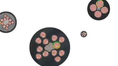
[…] Construction: Class 5 fine stranded copper conductors per VDE 0295, EPR rubber insulation per DIN VDE 0282 Part 4, Polychloroprene (Neoprene) outer sheath. Temperature: -25°C to +60°C (flexible), up to +90°C (fixed). Standards: EN 50525-2-21, IEC 60245-4, HD 22.4 S3, VDE 0282. Features: Oil resistant, ozone resistant, UV resistant, flame retardant (IEC 60332-1-2), water resistant (AD8). Applications: Mobile power supplies, construction sites, industrial equipment, cranes, stage lighting, outdoor events. Source: Feichun Cable – What is a Type H07RN-F Cable? […]