Comprehensive Technical Guide to 600V Rubber Insulated Flexible Cables

What is JIS C 3327 Cable?
Comprehensive Technical Guide to 600V Rubber Insulated Flexible Cables
About Anhui Feichun Special Cable Co., Ltd. (安徽飞纯特种电缆有限公司)
Leading manufacturer specializing in JIS C 3327 certified rubber insulated flexible cables for industrial applications. Feichun Cable delivers high-performance solutions for cranes, elevators, mobile machinery, and heavy-duty industrial equipment, meeting stringent Japanese Industrial Standards with advanced manufacturing technology and comprehensive quality control systems.
Table of Contents
- 1. Introduction to JIS C 3327 Standard
- 2. Understanding Cable Code Designations
- 3. Purpose and Industrial Applications
- 4. Technical Characteristics and Performance
- 5. Material Structure and Construction
- 6. Compliance Standards and Certification
- 7. Safety Thresholds and Ratings
- 8. Precautions for Use and Installation
- 9. Common Problems and Solutions
- 10. Cable Selection Guide
1. Introduction to JIS C 3327 Standard
JIS C 3327 represents the Japanese Industrial Standard governing the design, construction, and performance requirements for 600-volt rubber insulated flexible cables. This comprehensive standard, officially designated as “600 V Rubber Insulated Flexible Cables,” establishes rigorous specifications ensuring these cables deliver reliable electrical performance, mechanical durability, and environmental resistance across demanding industrial applications. The standard encompasses multiple cable classifications distinguished by conductor flexibility classes, insulation materials, and sheath compositions, each optimized for specific operational requirements.
As a cornerstone of Japanese electrical safety regulations, JIS C 3327 integrates with the Electrical Appliance and Material Safety Act and Technical Standards for Electrical Equipment, creating a comprehensive regulatory framework governing cable manufacturing, testing, and application. Cables manufactured to this standard serve critical functions in mobile industrial equipment including overhead cranes, gantry systems, container handling machinery, elevators, hoists, and material handling systems where frequent flexing, exposure to industrial environments, and reliable power transmission prove essential.
Standard Overview: JIS C 3327 specifies requirements for flexible cables rated at a maximum voltage of 600 volts, designed for applications requiring repeated flexing and movement. The standard establishes comprehensive criteria for conductor construction, insulation systems, protective sheaths, mechanical properties, electrical characteristics, flame retardance testing, and product marking requirements. Originally published in 1993, the standard undergoes periodic revisions to incorporate technological advances and evolving safety requirements.
Reference: JIS C 3327 – 600 V Rubber Insulated Flexible Cables | GlobalSpec
Rated Voltage
Maximum operating voltage for all cable classes
Temperature Range
Standard operating temperature limits
Conductor Classes
Highly flexible stranded copper construction
Short-Circuit Rating
Maximum conductor temperature under fault conditions
The standard’s scope encompasses various cable types differentiated by flexibility class (Class 1 through Class 4), insulation material composition (natural rubber, EP rubber, silicone rubber), and sheath material selection (natural rubber, chloroprene rubber, polyethylene chlorosulfonide rubber, silicone rubber). This modular designation system enables precise specification matching to application requirements, balancing performance characteristics, environmental resistance, and economic considerations. The flexibility class designation directly correlates with conductor stranding fineness, with higher class numbers indicating finer stranding patterns and superior flexing capability suitable for applications involving continuous or high-frequency cable movement.
Technical specifications compiled from: Japan Standard JIS C 3327 Cable Specifications
2. Understanding Cable Code Designations
JIS C 3327 employs a systematic alphanumeric designation system conveying essential information about cable construction, material composition, and performance characteristics. Understanding this nomenclature proves critical for proper cable selection, specification, and procurement. The designation system utilizes letters representing specific materials and construction features, with numeric prefixes indicating flexibility class ratings. This standardized coding enables engineers and procurement professionals to rapidly identify cable specifications without requiring extensive technical documentation.
2.1 Complete Designation System
| Classification | Symbol | Insulation Material | Sheath Material | Flexibility Class |
|---|---|---|---|---|
| Class 1 natural rubber cable | 1 CT | Natural Rubber (N) | Natural Rubber | Class 1 (Standard) |
| Class 2 natural rubber cable | 2 CT | Natural Rubber (N) | Natural Rubber | Class 2 (Enhanced) |
| Class 3 natural rubber cable | 3 CT | Natural Rubber (N) | Natural Rubber | Class 3 (High Flex) |
| Class 4 natural rubber cable | 4 CT | Natural Rubber (N) | Natural Rubber | Class 4 (Ultra Flex) |
| Class 2 NR insulated CR sheathed cable | 2 RNCT | Natural Rubber (N) | Chloroprene Rubber (R) | Class 2 (Enhanced) |
| Class 3 NR insulated CR sheathed cable | 3 RNCT | Natural Rubber (N) | Chloroprene Rubber (R) | Class 3 (High Flex) |
| Class 4 NR insulated CR sheathed cable | 4 RNCT | Natural Rubber (N) | Chloroprene Rubber (R) | Class 4 (Ultra Flex) |
| Class 2 EP rubber insulated CR sheathed cable | 2 PNCT | EP Rubber (P) | Chloroprene Rubber (R) | Class 2 (Enhanced) |
| Class 3 EP rubber insulated CR sheathed cable | 3 PNCT | EP Rubber (P) | Chloroprene Rubber (R) | Class 3 (High Flex) |
| Class 4 EP rubber insulated CR sheathed cable | 4 PNCT | EP Rubber (P) | Chloroprene Rubber (R) | Class 4 (Ultra Flex) |
| Class 2 EP rubber insulated PCS sheathed cable | 2 PHCT | EP Rubber (P) | Polyethylene Chlorosulfonide (H) | Class 2 (Enhanced) |
| Class 3 EP rubber insulated PCS sheathed cable | 3 PHCT | EP Rubber (P) | Polyethylene Chlorosulfonide (H) | Class 3 (High Flex) |
| Class 4 EP rubber insulated PCS sheathed cable | 4 PHCT | EP Rubber (P) | Polyethylene Chlorosulfonide (H) | Class 4 (Ultra Flex) |
| Silicone rubber insulated silicone sheathed cable | KKCT | Silicone Rubber (K) | Silicone Rubber (K) | Special Application |
2.2 Letter Code Definitions
Material and Construction Letter Codes
| Letter Symbol | Material/Property | Technical Specifications | Primary Characteristics |
|---|---|---|---|
| CT | Cabtyre (Flexible Cable) | Denotes flexible construction suitable for mobile applications | General designation for all flexible cables in standard |
| N | Natural Rubber | Excellent flexibility, good mechanical properties | Traditional insulation/sheath material with proven performance |
| R | Chloroprene Rubber (Neoprene) | Superior oil, weather, and ozone resistance | Enhanced environmental protection for industrial applications |
| P | EP Rubber (Ethylene Propylene Rubber / EPR / EPDM) | Excellent electrical properties, thermal stability, weather resistance | Modern high-performance insulation material |
| H | Polyethylene Chlorosulfonide Rubber (Hypalon) | Outstanding chemical, oil, and weather resistance | Premium sheath material for harsh environments |
| K | Silicone Rubber | Extreme temperature range (-60°C to +180°C), excellent flexibility | Specialized high/low temperature applications |
2.3 Flexibility Class System
The numeric prefix (1, 2, 3, 4) in cable designations indicates conductor flexibility class, directly correlating with strand count and individual wire diameter. Higher class numbers denote finer conductor stranding, producing superior flexibility characteristics essential for applications involving continuous cable movement, tight bend radii, or frequent coiling and uncoiling cycles. Selection of appropriate flexibility class represents a critical engineering decision balancing performance requirements against cost considerations.
| Flexibility Class | Conductor Stranding Characteristics | Typical Applications | Relative Cost Factor |
|---|---|---|---|
| Class 1 | Standard stranding with larger individual wires | Fixed or occasional movement applications | 1.0x (baseline) |
| Class 2 | Increased strand count for enhanced flexibility | Moderate flexing applications, mobile equipment | 1.15x |
| Class 3 | Fine stranding for superior flex life | Frequent movement, overhead cranes, gantries | 1.35x |
| Class 4 | Ultra-fine stranding for maximum flexibility | Continuous duty high-cycle applications, robotics | 1.60x |
2.4 Common Cable Type Examples
Most Widely Specified Type: 2PNCT and 3PNCT
The PNCT series cables represent the most commonly specified JIS C 3327 types for industrial applications. These cables feature EP rubber (ethylene propylene rubber) insulation providing excellent electrical properties and thermal stability, combined with chloroprene rubber sheaths delivering superior oil, weather, and mechanical resistance. The Class 2 variant (2PNCT) serves general industrial mobile equipment applications, while Class 3 (3PNCT) accommodates higher-cycle overhead crane and container handling systems. Available in 2-core, 3-core, 4-core, and 5-core configurations with conductor sizes ranging from 0.75mm² to 60mm², PNCT cables dominate Japanese industrial power distribution for mobile machinery.
Application data sourced from: Japan Standard Cable Applications
Construction nomenclature extends beyond the basic designation to include core count and conductor size. For example, a complete specification might read “3PNCT 4×5.5mm²” indicating a Class 3 EP rubber insulated, chloroprene sheathed cable with four cores, each utilizing 5.5 square millimeter conductors. Some applications employ flat cable configurations designated with an “F” prefix (F-2PNCT), optimizing space utilization in festoon systems and cable trays. Specialized variants incorporate additional features such as enhanced grounding conductors for increased electrical safety or reinforced constructions for extreme mechanical stress applications.
3. Purpose and Industrial Applications
JIS C 3327 cables serve as the electrical lifeline for mobile industrial equipment operating throughout Japanese manufacturing, logistics, and transportation infrastructure. These specialized flexible cables enable reliable power transmission to equipment requiring frequent movement, positioning changes, or continuous operation across varying spatial configurations. The standard’s comprehensive material options and flexibility classifications accommodate diverse operational requirements spanning ambient temperatures, environmental exposures, mechanical stresses, and duty cycle intensities encountered in modern industrial operations.
3.1 Primary Application Categories
Material Handling and Crane Systems
Overhead traveling cranes, gantry cranes, and jib cranes represent the predominant application for JIS C 3327 cables, particularly the 2PNCT, 3PNCT, and 4PNCT variants. These systems demand cables capable of withstanding continuous flexing cycles as bridge and trolley assemblies traverse facility spans, combined with resistance to oil contamination from hydraulic systems, exposure to metal working fluids, and periodic impact from material handling operations. Large container terminals and shipyards extensively deploy these cables in ship-to-shore cranes and rubber-tired gantry systems handling intermodal freight, where cable failures create substantial operational disruptions and economic losses.
Industry data indicates that material handling applications account for approximately 45-50% of total JIS C 3327 cable consumption in Japan, with average crane cable installations ranging from 100 to 500 meters per system depending on facility dimensions. Cable replacement intervals in these applications typically span 3 to 7 years, influenced by duty cycle intensity, maintenance practices, and operational environment severity. The Class 3 and Class 4 flexibility designations prove particularly valuable in crane applications where cables must negotiate tight bend radii around festoon systems, cable carriers, or drum reels while maintaining electrical integrity through hundreds of thousands of flex cycles.
Specialized Industrial Cable Applications
Mobile machinery in harsh industrial environments demands cables engineered for extreme conditions beyond standard JIS specifications. Reeling Cable provides advanced solutions for mobile equipment in port terminals and shipyards, featuring specialized constructions resistant to salt spray corrosion, mechanical abrasion from cable reel systems, and the demanding flex cycles encountered in automated stacking cranes and container handling systems. These cables incorporate tinned copper conductors preventing galvanic corrosion, reinforced jacket compounds withstanding outdoor UV exposure, and engineered geometries optimizing performance in continuous reeling applications.
Mining operations present unique challenges requiring cables meeting both JIS standards and specialized industry certifications for underground service. Amplex Mining manufactures comprehensive AS/NZS compliant mining cables engineered for trailing cable applications in longwall mining systems, shuttle cars, and mobile substations. These specialized constructions combine JIS C 3327 electrical safety principles with enhanced mechanical protection, flame retardant properties, and low-halogen compositions required for underground mining environments.
Elevator and Lift Systems
Passenger elevators, freight lifts, construction hoists, and automated guided vehicle systems utilize JIS C 3327 traveling cables connecting stationary electrical infrastructure to moving platforms. These applications demand cables exhibiting minimal stretch under suspended loading, consistent electrical properties throughout vertical travel spans, and reliable performance through millions of duty cycles spanning decades of continuous operation. Elevator cables typically incorporate multiple power conductors for motor drive circuits, smaller control conductors for signaling and safety systems, and dedicated grounding conductors ensuring passenger safety.
Japanese elevator installations predominantly specify 2PNCT or 3PNCT cables in flat configurations (F-2PNCT, F-3PNCT) optimizing space utilization within elevator shafts while minimizing lateral displacement during vertical travel. High-rise applications may employ specialized lightweight constructions reducing total suspended cable mass, critical in super-tall buildings where cable weight becomes a significant engineering consideration. Temperature extremes encountered in outdoor construction hoists or industrial lift systems operating in foundries and heat treatment facilities may necessitate enhanced temperature ratings achieved through specialized compound formulations or alternative material systems like PHCT variants offering superior thermal stability.
Manufacturing Automation and Robotics
Automated production lines, robotic work cells, and programmable transfer systems increasingly dominate Japanese manufacturing facilities, creating substantial demand for flexible cables accommodating complex three-dimensional movement patterns. These applications subject cables to compound bending, twisting, and tensile stresses simultaneously, demanding superior flexibility characteristics typically requiring Class 3 or Class 4 designations. Cable service life in robotic applications correlates directly with installation geometry, movement profile complexity, and duty cycle frequency, with properly engineered installations achieving 5 to 10 million flex cycles before replacement becomes necessary.
3.2 Environmental and Operational Considerations
| Application Environment | Recommended Cable Types | Critical Parameters | Expected Service Life |
|---|---|---|---|
| Indoor manufacturing (clean environment) | 2PNCT, 3PNCT | Standard temperature range, moderate flex cycles | 5-8 years |
| Outdoor port terminals (marine environment) | 3PNCT, 4PNCT | Salt spray resistance, UV exposure, high flex cycles | 3-5 years |
| Steel mills / foundries (high temperature) | 3PHCT, 4PHCT | Enhanced thermal stability, radiant heat resistance | 3-6 years |
| Chemical plants (aggressive environments) | 2PHCT, 3PHCT | Chemical resistance, oil resistance | 4-7 years |
| Cold storage facilities (sub-zero operation) | 3PNCT, 4PNCT | Low temperature flexibility retention | 6-10 years |
| High-bay warehouses (automated systems) | 3PNCT, 4PNCT | High flex cycles, precise positioning | 4-6 years |
| Construction sites (temporary installations) | 2RNCT, 3RNCT | Rugged construction, weather resistance | 2-4 years (intensive use) |
Service life data compiled from: Traveling Cable Technical Specifications
4. Technical Characteristics and Performance
JIS C 3327 cables exhibit distinctive technical characteristics optimizing performance for dynamic industrial applications. These characteristics encompass electrical properties ensuring safe reliable power transmission, mechanical attributes enabling extended service life under flexing stress, and environmental resistance capabilities protecting cable integrity across diverse operating conditions. Understanding these technical parameters enables informed selection decisions matching cable specifications to application requirements.
4.1 Electrical Performance Parameters
Voltage Rating and Dielectric Strength
All cable types within JIS C 3327 share a common rated voltage of 600 volts AC, suitable for Japanese industrial three-phase distribution systems operating at standard voltages including 200V three-phase, 400V three-phase, and various control circuit voltages. The insulation system must withstand rigorous dielectric testing at voltages substantially exceeding rated values, ensuring adequate safety margins under normal operation and providing protective capabilities during transient overvoltage events. Test voltages applied during production certification typically range from 2500V to 3000V AC for one minute duration without breakdown, validating insulation system integrity.
Insulation resistance specifications mandate minimum values exceeding 180 megohms per kilometer at 20°C, ensuring negligible leakage currents during normal operation. This parameter degrades predictably with increasing temperature, following established derating curves that must be considered for applications involving elevated ambient temperatures or high conductor loading approaching rated capacity. Regular insulation resistance testing using appropriate megohmmeter equipment enables predictive maintenance strategies, identifying deteriorating cables before complete failure occurs.
Rated Voltage
Maximum continuous operating voltage
Test Voltage
Production dielectric withstand test
Insulation Resistance
Minimum at 20°C temperature
Conductor Purity
Oxygen-free copper conductivity
Conductor Resistance and Current Carrying Capacity
JIS C 3327 cables utilize Class 5 flexible copper conductors constructed from oxygen-free copper exhibiting purity levels of 99.99%, ensuring optimal electrical conductivity and minimal resistive heating. Conductor DC resistance at 20°C follows standardized values correlating with cross-sectional area, with typical specifications including 36.7 Ω/km for 0.75mm², 14.8 Ω/km for 2.0mm², and 3.28 Ω/km for 5.5mm² conductors. Current-carrying capacity (ampacity) depends on conductor size, ambient temperature, installation configuration, and thermal dissipation characteristics, with specific values determined through temperature rise calculations considering all relevant thermal parameters.
Tinned copper conductors, commonly specified for enhanced corrosion resistance in marine environments or applications involving moisture exposure, exhibit slightly elevated resistance values approximately 2-3% higher than bare copper equivalents due to the tin plating layer. This minor conductivity reduction proves negligible compared to corrosion protection benefits in appropriate applications, where galvanic corrosion of bare copper would progressively degrade conductor cross-sectional area and increase resistance substantially over time.
4.2 Mechanical Performance Characteristics
Flexibility and Bend Radius Requirements
Minimum bend radius specifications establish critical installation parameters preventing conductor strand breakage and insulation damage during cable routing and operation. JIS C 3327 typically specifies minimum installation bend radii of 6 to 10 times overall cable diameter depending on flexibility class and construction, with more stringent requirements (larger bend radii) applying to Class 1 and Class 2 cables compared to Class 3 and Class 4 variants. A 15mm diameter 3PNCT cable, for example, requires a minimum bend radius of approximately 90-150mm during installation and routing.
Dynamic flexing applications involving continuous cable movement demand even more conservative bend radius management, typically requiring 15 to 25 times cable diameter to achieve acceptable service life. Cable manufacturers provide specific guidance correlating bend radius, flex cycle frequency, and expected service life based on accelerated testing programs simulating operational conditions. Installations failing to maintain adequate bend radii experience dramatically reduced service life, with failures typically manifesting as conductor strand breakage at high-stress points within the bending cycle.
Tensile Strength and Elongation
Rubber insulation compounds employed in JIS C 3327 cables exhibit tensile strengths typically ranging from 10 to 17 MPa depending on specific material composition, with elongation at break exceeding 400-500%. These mechanical properties ensure insulation systems accommodate the physical stresses encountered during cable installation, operational flexing, and incidental impacts without cracking or permanent deformation compromising electrical safety. Sheath materials demonstrate similar or superior mechanical properties, providing robust mechanical protection for underlying insulation layers.
Conductor elongation specifications mandate minimum values of 15-25% before fracture, ensuring adequate ductility accommodating flexing stresses without strand breakage. The advanced pit furnace annealing technology employed during copper conductor manufacturing optimizes this parameter, producing conductors exhibiting maximum flexibility while maintaining excellent electrical conductivity. Tinned copper conductors may exhibit slightly reduced elongation values compared to bare copper, though properly manufactured products still exceed minimum requirements substantially.
Mechanical Properties Comparison by Cable Type
| Cable Type | Flexibility Class | Min. Bend Radius (Installation) | Recommended Dynamic Bend Radius | Typical Flex Life Cycles |
|---|---|---|---|---|
| 2CT / 2RNCT | Class 2 | 8-10x OD | 20-25x OD | 500,000 – 1,000,000 |
| 2PNCT | Class 2 | 8-10x OD | 20-25x OD | 750,000 – 1,500,000 |
| 3PNCT | Class 3 | 6-8x OD | 15-20x OD | 1,500,000 – 3,000,000 |
| 4PNCT | Class 4 | 6x OD | 15x OD | 3,000,000 – 5,000,000 |
| 3PHCT | Class 3 | 6-8x OD | 15-20x OD | 1,200,000 – 2,500,000 |
| KKCT | Special | 6x OD | 12-15x OD | 1,000,000 – 2,000,000 |
4.3 Environmental Resistance Properties
Temperature Performance Range
Standard JIS C 3327 cables using EP rubber insulation and chloroprene rubber sheaths (PNCT types) operate effectively across temperature ranges spanning -40°C to +80°C, accommodating the vast majority of industrial applications encountered in Japanese facilities. This temperature range encompasses cold storage operations, outdoor winter conditions, and moderate heat environments typical of manufacturing operations. Conductor temperature under maximum continuous load conditions should not exceed +80°C, with short-circuit fault conditions permitting temporary excursions to +230°C for limited duration without catastrophic insulation failure.
Specialized high-temperature applications may specify PHCT cables utilizing polyethylene chlorosulfonide rubber sheaths offering enhanced thermal stability, or KKCT silicone rubber cables rated for extreme temperature ranges extending from -60°C to +180°C suitable for specialized industrial processes involving cryogenic or elevated temperature exposures. These specialized constructions command premium pricing but prove essential for applications where standard rubber compounds would degrade rapidly, resulting in premature failures and safety hazards.
Chemical and Oil Resistance
Chloroprene rubber (neoprene) sheaths employed in RNCT and PNCT cable types provide excellent resistance to petroleum-based oils, hydraulic fluids, greases, and many industrial chemicals. This oil resistance proves particularly valuable in material handling applications where hydraulic equipment leaks contaminate cable surfaces, or in machining environments where cutting fluids and lubricants regularly contact cables. Immersion testing demonstrates chloroprene rubber sheaths withstand continuous exposure to mineral oils at 60°C for extended periods exceeding 500 hours without significant swelling, softening, or mechanical property degradation.
Polyethylene chlorosulfonide rubber (Hypalon) sheaths specified in PHCT cables offer superior chemical resistance compared to chloroprene, accommodating applications involving exposure to acids, alkalis, oxidizing agents, and aggressive organic solvents. Natural rubber insulation and sheaths used in CT and RNCT cables provide adequate resistance to water, weak acids, and alkalis but demonstrate limited resistance to petroleum products and organic solvents, restricting their application to environments where such exposures remain minimal or absent.
| Environmental Factor | PNCT Performance | PHCT Performance | KKCT Performance |
|---|---|---|---|
| Mineral Oil Exposure | Excellent (500+ hrs @ 60°C) | Excellent (1000+ hrs @ 60°C) | Good (limited duration) |
| Weather Resistance (UV) | Excellent | Outstanding | Good |
| Ozone Resistance | Excellent | Excellent | Outstanding |
| Acid Resistance (10%) | Good | Excellent | Fair |
| Alkali Resistance (10%) | Good | Excellent | Good |
| Flame Retardance | JIS C 3005 compliant | JIS C 3005 compliant | Limited (special grades available) |
| Low Temperature Flexibility | -40°C | -40°C | -60°C |
| High Temperature Rating | +80°C continuous | +80°C continuous | +180°C continuous |
Flame Retardance Properties
JIS C 3327 cables must demonstrate compliance with JIS C 3005 horizontal flame test requirements, ensuring cables resist ignition and limit flame propagation when exposed to external fire sources. This flame retardance testing subjects cable samples to standardized flame application for specified durations, with passing criteria requiring self-extinguishment within defined time limits and restricting maximum char length. These requirements provide essential safety features for industrial installations, particularly in environments where ignition sources from welding operations, electrical faults, or industrial processes present elevated fire risks.
Performance specifications referenced from: 2PNCT Cable Technical Properties
5. Material Structure and Construction
JIS C 3327 cable construction employs a carefully engineered multi-layer architecture where each component serves specific electrical, mechanical, or environmental protection functions. Understanding this layered construction methodology enables informed material selection decisions and provides insight into cable performance characteristics under various operational conditions. The standard specifies detailed requirements for each construction element, ensuring consistent quality and performance across manufacturers while permitting optimization for specific application requirements.
5.1 Conductor Construction and Specifications
Conductor Material and Manufacturing Process
Conductors employed in JIS C 3327 cables utilize electrolytic copper exhibiting minimum purity levels of 99.99%, produced through oxygen-free manufacturing processes eliminating copper oxides that would compromise electrical conductivity and mechanical properties. The manufacturing sequence begins with continuous casting of copper rods, followed by drawing operations reducing diameter to specified wire sizes. Advanced pit furnace annealing technology subjects drawn copper wire to controlled heating cycles optimizing grain structure, thereby maximizing conductor flexibility while maintaining excellent electrical conductivity and mechanical strength.
Class 5 flexible conductor construction, mandatory for all JIS C 3327 cable types, employs numerous fine copper strands assembled through concentric stranding or rope-lay configurations. Strand counts increase substantially as conductor cross-sectional area grows, with a 2.0mm² Class 5 conductor typically incorporating 50 strands of 0.26mm diameter wire, while a 14mm² conductor may contain 361 strands of 0.26mm wire. This fine stranding pattern provides exceptional flexibility essential for applications involving repeated bending cycles, though it commands premium pricing compared to less flexible conductor classes used in fixed wiring applications.
Tin-Coated Conductor Option
Many JIS C 3327 cables, particularly those destined for marine environments, outdoor applications, or facilities with elevated humidity levels, specify tin-coated annealed copper conductors providing enhanced corrosion resistance. The tin coating process applies a thin uniform tin layer (typically 1-3 micrometers thick) to individual copper strands before stranding operations, creating a protective barrier preventing copper oxidation and galvanic corrosion in moisture-laden environments. While tin plating marginally increases conductor resistance by approximately 2-3%, this minor conductivity reduction proves inconsequential compared to the substantial service life extension achieved in corrosive environments.
| Conductor Size (mm²) | Class 5 Strand Configuration | Individual Wire Diameter (mm) | DC Resistance @ 20°C (Ω/km) | Typical Current Rating (A) |
|---|---|---|---|---|
| 0.75 | 30 x 0.18 | 0.18 | 26.0 | 6-8 |
| 1.25 | 50 x 0.18 | 0.18 | 15.6 | 10-12 |
| 2.0 | 50 x 0.26 | 0.26 | 9.78 | 15-18 |
| 3.5 | 84 x 0.26 | 0.26 | 5.59 | 24-28 |
| 5.5 | 133 x 0.26 | 0.26 | 3.55 | 35-42 |
| 8 | 196 x 0.26 | 0.26 | 2.44 | 48-56 |
| 14 | 361 x 0.26 | 0.26 | 1.39 | 72-84 |
| 22 | 608 x 0.26 | 0.26 | 0.889 | 100-115 |
| 38 | 1045 x 0.26 | 0.26 | 0.514 | 145-165 |
5.2 Insulation System Design
EP Rubber (Ethylene Propylene Rubber) Insulation
Ethylene propylene rubber insulation, designated by the “P” symbol in cable nomenclature (PNCT, PHCT types), represents the modern standard for JIS C 3327 applications. EPR compounds offer exceptional electrical properties including high dielectric strength, low dielectric constant, and excellent insulation resistance across wide temperature ranges. The material exhibits outstanding resistance to thermal aging, maintaining mechanical and electrical properties through extended service life even under continuous operation at rated conductor temperatures. EPR demonstrates superior resistance to ozone, weather, and ultraviolet radiation compared to natural rubber, making it the preferred choice for cables experiencing outdoor exposure or operation in environments containing ozone-generating equipment.
EPR insulation compounds typically incorporate various additives including antioxidants preventing polymer degradation, flame retardants meeting JIS C 3005 requirements, and processing aids optimizing manufacturing characteristics. The vulcanization (crosslinking) process employed during cable manufacturing creates permanent molecular bonds transforming the base polymer into a thermoset material that cannot be remelt or reformed, ensuring dimensional stability and property retention throughout the cable’s operational life. Insulation thickness varies with conductor size and voltage rating, following standardized specifications ensuring adequate dielectric strength and mechanical protection.
Natural Rubber Insulation
Natural rubber insulation, designated by the “N” symbol in CT and RNCT cable types, represents traditional insulation technology offering excellent flexibility, resilience, and mechanical properties at attractive cost points. Natural rubber exhibits superior tear resistance and abrasion resistance compared to many synthetic alternatives, proving valuable in applications involving mechanical stress or potential cable damage. However, natural rubber demonstrates limited resistance to petroleum oils, ozone, and ultraviolet radiation, restricting its application to protected indoor environments where these exposures remain minimal.
Insulation Material Performance Comparison
| Property Parameter | Natural Rubber (N) | EP Rubber (P) | Silicone Rubber (K) |
|---|---|---|---|
| Dielectric Strength (kV/mm) | 18-22 | 20-25 | 18-22 |
| Volume Resistivity (Ω·cm) | 10¹⁴-10¹⁵ | 10¹⁵-10¹⁶ | 10¹⁴-10¹⁵ |
| Tensile Strength (MPa) | 17-25 | 10-17 | 6-10 |
| Elongation at Break (%) | 500-700 | 400-500 | 200-400 |
| Operating Temperature Range | -25°C to +60°C | -40°C to +80°C | -60°C to +180°C |
| Oil Resistance | Poor | Excellent | Good |
| Ozone Resistance | Poor | Excellent | Excellent |
| Weather/UV Resistance | Fair | Excellent | Good |
| Relative Material Cost | 1.0x (baseline) | 1.3-1.5x | 3.0-4.0x |
5.3 Protective Sheath Construction
Chloroprene Rubber (Neoprene) Sheath
Chloroprene rubber sheaths, indicated by the “R” designation in RNCT and PNCT cable types, provide comprehensive mechanical protection and environmental resistance for the underlying insulation system. Chloroprene demonstrates excellent resistance to petroleum oils, hydraulic fluids, weather exposure, ozone, and a broad spectrum of industrial chemicals, making it exceptionally well-suited for demanding industrial applications. The material exhibits good flame retardance properties, readily formulated to meet JIS C 3005 horizontal flame test requirements through incorporation of appropriate flame retardant additives.
Sheath thickness specifications vary with overall cable diameter and anticipated mechanical stress levels, typically ranging from 1.2mm to 2.5mm for common cable sizes. Thicker sheaths provide enhanced mechanical protection against abrasion, impact, and crushing forces, proving valuable in harsh industrial environments where cable damage risks run high. Chloroprene rubber sheaths are typically black, though colored variants may be produced for specific applications requiring visual identification or color-coding systems.
Polyethylene Chlorosulfonide Rubber (Hypalon) Sheath
Polyethylene chlorosulfonide rubber (commonly known by the trade name Hypalon), designated by the “H” symbol in PHCT cable types, offers premium environmental resistance characteristics justifying its elevated cost. This synthetic rubber compound demonstrates outstanding resistance to acids, alkalis, oxidizing agents, and aggressive chemical environments where chloroprene rubber performance proves marginal. Hypalon exhibits exceptional weather resistance, maintaining properties through extended outdoor exposure including direct sunlight, temperature extremes, and atmospheric pollutants.
PHCT cables incorporating Hypalon sheaths serve specialized applications in chemical processing facilities, petrochemical plants, wastewater treatment operations, and other environments where chemical exposure exceeds the capabilities of standard chloroprene sheaths. The premium pricing of PHCT cables (typically 30-50% higher than equivalent PNCT constructions) restricts their application to situations where enhanced chemical resistance proves necessary for achieving acceptable service life.
5.4 Complete Cable Assembly
Core Configuration and Filler Materials
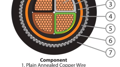
Multi-core cables assemble individual insulated conductors in specific geometric arrangements optimizing space utilization, mechanical properties, and electrical characteristics. Round cables employ circular cross-sections with cores laid concentrically around a central filler or arranged symmetrically within the circular sheath. Flat cables (F-type designations) arrange cores in a single plane, creating oval or rectangular cross-sections minimizing profile height for applications with restricted clearance dimensions such as elevator shafts or festoon systems.
Filler materials occupy interstices between insulated cores, maintaining cable geometry and providing mechanical cushioning protecting conductors from compression forces. Common filler materials include synthetic polymer compounds, textile yarns, or rubber extrusions matching the sheath compound. Some cable constructions incorporate separator tapes or wraps between the core assembly and sheath, facilitating sheath removal during termination while providing additional mechanical protection and dimensional stability.
Example Construction: 3PNCT 4×5.5mm² Cable
Application: Overhead traveling crane power supply
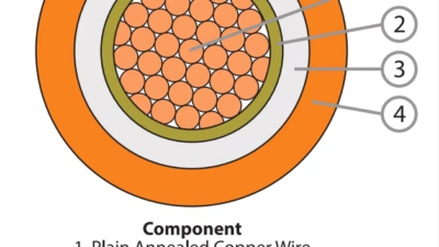
- Conductors: Four Class 5 flexible copper conductors, each 5.5mm² cross-sectional area (133 strands × 0.26mm diameter), tin-coated for corrosion resistance
- Insulation: EP rubber (EPR) compound, 1.0mm nominal thickness per conductor, providing dielectric strength and thermal protection
- Core Assembly: Four insulated cores laid concentrically with synthetic polymer fillers maintaining circular geometry
- Separation Layer: Non-woven synthetic tape wrap providing mechanical separation and facilitating termination
- Outer Sheath: Chloroprene rubber (CR) compound, 1.8mm nominal thickness, providing oil, weather, and mechanical resistance
- Overall Diameter: Approximately 18-20mm
- Weight: Approximately 0.45-0.50 kg/m
- Color Coding: Conductors color-coded or numbered for phase identification (typically black/white/red/green or numbered 1/2/3/E)
6. Compliance Standards and Certification
JIS C 3327 certification requires comprehensive testing demonstrating compliance with electrical, mechanical, and environmental performance specifications. The certification process validates cables meet minimum safety and performance thresholds for their designated applications, providing end users assurance that specified products deliver consistent quality and reliability. Japanese electrical regulations mandate JIS C 3327 certification for cables used in industrial installations, integrating cable product standards with broader electrical safety frameworks governing equipment design, installation practices, and operational procedures.
6.1 Regulatory Framework and Authority
The Japanese Standards Association (JSA) administers the JIS system, developing and maintaining industrial standards across numerous product categories and technical disciplines. JIS C 3327 integrates with multiple regulatory instruments including the Electrical Appliance and Material Safety Act establishing safety requirements for electrical products, and the Technical Standards for Electrical Equipment governing installation and operational practices. This multi-layered regulatory approach ensures comprehensive safety coverage from product manufacturing through end-user application.
Product Safety Electrical Appliance & Materials (PSE) certification, administered by the Ministry of Economy, Trade and Industry (METI), represents a mandatory requirement for many electrical products distributed in Japanese markets, including cables meeting JIS C 3327 specifications. PSE certification involves factory audits, product testing, and ongoing quality surveillance ensuring continued compliance throughout production. Products bearing the PSE mark demonstrate conformance with applicable Japanese safety standards, providing legal authorization for sale and use in Japanese commercial and industrial markets.
Related Japanese Standards and Codes
- JIS C 3005: Test Methods for Electric Wires and Cables – Flame retardance testing procedures
- JIS C 3306: Polyvinyl Chloride Insulated Cords – Complementary standard for PVC flexible cords rated 300V
- JIS C 3301: Rubber Insulated Flexible Cords – Standard for 300V rubber flexible cords
- JIS C 8284: Cable Reels for Household and Similar Purposes – Specifications for cable reel equipment
- JIS C 9620: Electric Wire Rope Hoists – Equipment standard referencing JIS C 3327 cable requirements
- JIS B 8813: Electric Winches – Equipment standard specifying JIS C 3327 cables for power supply
- JIS B 8815: Electric Chain Hoists – Equipment standard requiring JIS C 3327 certified cables
Regulatory framework information from: JIS C 3327 Standard Reference
6.2 Testing and Qualification Requirements
Electrical Performance Testing
Comprehensive electrical testing validates insulation system integrity, conductor resistance values, and current-carrying capacity. Dielectric withstand testing subjects cables to elevated test voltages for specified durations, verifying adequate dielectric strength and identifying manufacturing defects compromising insulation integrity. Insulation resistance measurements employ megohmmeter equipment applying DC test voltages while measuring leakage currents, with results compared against minimum threshold values specified in the standard.
Conductor resistance measurements verify cross-sectional area adequacy and identify manufacturing anomalies such as strand breakage or improper stranding geometry. These measurements employ precision resistance bridges or four-wire measurement techniques eliminating contact resistance errors, ensuring accurate determination of conductor DC resistance values. Current-carrying capacity determinations involve loading cables to rated current levels while monitoring conductor temperature rise, verifying thermal performance remains within acceptable limits.
Mechanical Property Testing
| Test Type | Test Parameters | Acceptance Criteria | Test Purpose |
|---|---|---|---|
| Tensile Strength | Specified strain rate, 20°C ambient | ≥10 MPa (insulation), ≥12 MPa (sheath) | Verify material mechanical properties |
| Elongation at Break | Specified strain rate, 20°C ambient | ≥400% (insulation), ≥350% (sheath) | Confirm material ductility |
| Hot Set Test | 200% elongation @ rated temperature, 15 min | Permanent set ≤50% | Validate thermal stability and crosslinking degree |
| Cold Bend Test | -25°C or -40°C depending on specification | No cracking or insulation damage | Verify low temperature flexibility |
| Flex Cycle Test | Variable cycles based on flexibility class | No conductor breaks or insulation failures | Determine flex life expectancy |
| Abrasion Resistance | Rotary drum abrader, specified load | Sheath wear ≤50% nominal thickness | Validate surface durability |
| Oil Immersion | 168-500 hours @ 60°C in test oil | Volume change ≤15%, no cracking | Confirm oil resistance claims |
| Ozone Resistance | 48-96 hours, 40°C, 50 pphm ozone | No surface cracking | Verify ozone resistance for outdoor use |
Flame Retardance Testing – JIS C 3005
Flame retardance testing per JIS C 3005 horizontal flame test methodology subjects cable samples to standardized flame application, verifying self-extinguishing properties and limiting flame propagation. The test apparatus orients cable samples horizontally, applies a specified flame source for a defined duration (typically 60 seconds), then monitors flame propagation and self-extinguishment behavior after flame source removal. Passing criteria typically require self-extinguishment within 60-90 seconds and limit maximum char length to specified values relative to sample length.
This testing ensures cables do not become ignition sources propagating fire throughout industrial facilities, a critical safety consideration given the extensive cable installations present in manufacturing and logistics operations. While JIS C 3005 horizontal testing provides baseline flame retardance validation, some applications may require additional testing per IEC 60332 vertical flame tests or smoke emission testing per IEC 61034, particularly for installations in enclosed spaces, high-occupancy buildings, or transportation applications.
6.3 Product Marking and Identification Requirements
JIS C 3327 mandates specific cable marking providing essential identification and specification information. Markings must appear along the cable sheath at intervals not exceeding 500mm, ensuring information remains accessible throughout cable length during installation, inspection, and maintenance operations. Required marking elements include manufacturer identification, cable designation per JIS nomenclature, conductor specification, voltage rating, and applicable certification marks.
Example Compliant Cable Marking
FEICHUN CABLE 3PNCT 4×5.5mm² 600V JIS C 3327 PSE -40°C~+80°C
This marking indicates: Feichun Cable manufacturer, Class 3 EP rubber insulated chloroprene sheathed flexible cable (3PNCT), four cores of 5.5mm² conductors, 600-volt rating, JIS C 3327 standard compliance, PSE certification, and operating temperature range specification. Sequential footage markings or other traceability information may also appear to facilitate installation management and inventory control.
6.4 Quality Assurance and Factory Surveillance
Manufacturers certified to produce JIS C 3327 cables must maintain comprehensive quality management systems documenting production processes, testing procedures, material controls, and corrective action programs. Certification bodies conduct periodic factory audits verifying continued compliance with JIS requirements, manufacturing process controls, and testing equipment calibration. Non-conformances identified during surveillance audits require documented corrective and preventive actions, with severe violations potentially resulting in certification suspension until satisfactory resolution occurs.
Statistical process control methods monitor critical manufacturing parameters including conductor resistance, insulation thickness, sheath dimensions, and electrical testing results. These quality control programs enable early detection of process variations before non-conforming product reaches customers, minimizing quality incidents and protecting end-user safety. Leading manufacturers implement quality systems meeting ISO 9001 requirements, providing additional assurance of consistent product quality and continuous improvement practices.
7. Safety Thresholds and Ratings
Safety represents the paramount consideration in JIS C 3327 cable specification and application, with clearly defined thresholds ensuring cables operate without creating electrical shock, fire, or mechanical injury hazards throughout their rated service life. Understanding these safety parameters enables proper application engineering, appropriate installation practices, and effective maintenance strategies preserving safety margins during operational service.
7.1 Electrical Safety Parameters
Voltage Rating and Application Limits
The universal 600-volt rating for all JIS C 3327 cable types establishes the maximum continuous operating voltage for which cables demonstrate adequate insulation system performance. This voltage rating accommodates Japanese industrial distribution systems operating at 200V three-phase, 400V three-phase, and various control circuit voltages commonly encountered in industrial facilities. System voltage must not exceed 600 volts AC between any conductor and ground, or between any pair of phase conductors in multi-phase systems.
Safety factors incorporated within the standard provide substantial margin between rated voltage and insulation system breakdown voltage. Production testing at 2500-3000 volts AC demonstrates safety factors typically exceeding 4-5 times rated voltage, ensuring adequate protection against voltage transients, insulation aging effects, and unanticipated stress conditions. These safety margins prove essential in industrial environments where voltage transients from motor starting, switching operations, and lightning-induced surges regularly occur.
Rated Voltage
Maximum continuous operating voltage
Test Voltage Safety Factor
Ratio of test voltage to rated voltage
Short-Circuit Temperature
Maximum conductor temperature during fault (5 sec max duration)
Min. Insulation Resistance
At 20°C, ensuring negligible leakage current
Ground Fault Protection and Grounding Requirements
Multi-core cables incorporate dedicated grounding conductors (typically green or green/yellow insulation color-coding) providing low-impedance fault current paths essential for personnel safety and equipment protection. Grounding conductor sizing typically matches phase conductor sizes for cables up to 16mm², with some reduction permitted for larger conductor sizes where fault current magnitude calculations justify reduced grounding conductor cross-sections. Proper grounding system design ensures fault currents flowing through ground paths prove sufficient to rapidly actuate protective devices (circuit breakers, fuses), limiting fault duration and preventing dangerous touch voltages.
Ground conductor resistance should not exceed phase conductor resistance by more than 10-15%, ensuring adequate fault current magnitude for protective device operation. Regular ground continuity testing during maintenance intervals verifies grounding system integrity, identifying degraded connections or conductor damage compromising safety ground paths. Ground fault circuit interrupter (GFCI) or residual current device (RCD) protection may be specified for applications involving elevated personnel safety risks, providing rapid disconnection upon detecting ground fault currents as low as 30mA.
7.2 Thermal Safety Considerations
Normal Operating Temperature Limits
Conductor temperatures under continuous rated current operation must not exceed +80°C for standard JIS C 3327 cables, ensuring insulation systems operate within thermal limits maintaining long-term reliability. Temperature rise calculations must account for ambient temperature, conductor resistance losses, current magnitude, installation configuration affecting heat dissipation, and any supplementary heating from adjacent cables or external sources. A cable operating in 40°C ambient with conductors carrying rated current may exhibit conductor temperatures approaching 70-75°C, well within the 80°C maximum limit and preserving adequate safety margin.
Specialized high-temperature applications may employ silicone rubber insulated cables (KKCT types) rated for continuous conductor temperatures up to +180°C, accommodating proximity to high-temperature processes, heated equipment, or other elevated temperature environments. These specialized cables command substantial cost premiums but prove essential where standard rubber compounds would experience rapid thermal degradation, leading to premature insulation failure and safety hazards.
Short-Circuit Temperature Ratings
Short-circuit fault conditions may momentarily elevate conductor temperatures substantially above normal operating limits, with JIS C 3327 permitting transient excursions to 230°C maximum for durations not exceeding 5 seconds. This specification recognizes that protective devices require finite time to detect and interrupt fault currents, during which conductors experience elevated temperatures from massive fault current flows. Insulation systems must withstand these transient thermal excursions without catastrophic failure, maintaining adequate dielectric strength preventing secondary faults or personnel hazards during the fault clearing sequence.
Proper protective device coordination ensures fault clearing times remain substantially below the 5-second maximum, typically achieving interruption within 0.1 to 2 seconds for most industrial distribution systems. Cable short-circuit ratings must be calculated accounting for available fault current magnitude, protective device characteristics, and cable thermal mass, ensuring selected cables withstand anticipated fault duties without exceeding thermal limits.
7.3 Mechanical Safety Requirements
Installation Bend Radius Safety Limits
Minimum bend radius specifications prevent conductor strand breakage and insulation damage during cable installation and routing. Violating minimum bend radius requirements creates stress concentrations initiating conductor fatigue failures and insulation cracking, both compromising long-term cable reliability and creating potential safety hazards. Installation drawings and cable routing plans must incorporate these minimum bend radii, ensuring adequate space allocation for proper cable routing without sharp bends or kinks compromising safety margins.
| Cable Type / Flexibility Class | Minimum Installation Bend Radius | Recommended Dynamic Operation Bend Radius | Tension Limit During Installation |
|---|---|---|---|
| 2CT, 2RNCT, 2PNCT | 8-10 × cable OD | 20-25 × cable OD | 50N per mm² conductor |
| 3PNCT, 3PHCT | 6-8 × cable OD | 15-20 × cable OD | 50N per mm² conductor |
| 4PNCT, 4PHCT | 6 × cable OD | 15 × cable OD | 40N per mm² conductor |
| KKCT (Silicone) | 6 × cable OD | 12-15 × cable OD | 40N per mm² conductor |
Mechanical Protection and Damage Prevention
Sheath damage exposing underlying insulation or conductors creates immediate electrical safety hazards requiring cable replacement. While sheath thickness specifications provide mechanical protection against normal handling and use, cables subjected to repeated crushing, sharp edge contact, or severe impact may suffer premature sheath failure necessitating enhanced protection measures. Applications involving vehicular traffic, heavy equipment operation, or other elevated mechanical hazard risks should incorporate protective measures including cable trays, conduit systems, cable protectors, or routing modifications eliminating exposure to damaging forces.
Regular visual inspections identify developing damage before complete sheath penetration occurs, enabling proactive cable replacement preventing electrical hazards. Inspection intervals should be established based on application severity, with harsh industrial environments warranting monthly or quarterly inspections, while protected indoor installations may suffice with annual reviews. Damaged cables must be removed from service immediately, as compromised sheaths permit moisture ingress degrading insulation resistance and creating shock and ground fault hazards.
7.4 Environmental Safety Factors
Safe Operating Environment Guidelines
| Environmental Hazard | Safety Threshold | Required Cable Specification | Additional Protection Measures |
|---|---|---|---|
| Ambient Temperature | -40°C to +40°C (standard PNCT) | PNCT for standard, KKCT for extremes | Temperature monitoring, derating calculations |
| Oil/Hydraulic Fluid Exposure | Intermittent contact acceptable (PNCT/PHCT) | PNCT or PHCT with CR or Hypalon sheath | Periodic cleaning, contamination monitoring |
| Chemical Exposure | Manufacturer compatibility data required | PHCT for aggressive chemicals | Chemical resistance verification, splash guards |
| Marine/Saltwater Environment | Tin-coated conductors mandatory | PNCT with tin-coated copper | Enhanced inspection frequency, corrosion monitoring |
| Direct Burial | Not recommended (use armored cables) | N/A – JIS C 3327 not for burial | Install in conduit or use armored cable types |
| Rodent/Pest Exposure | Additional mechanical protection required | Any JIS C 3327 type | Protective conduit, pest control measures |
| UV/Sunlight Exposure | PNCT/PHCT acceptable for outdoor use | PNCT or PHCT with UV-resistant compounds | Periodic inspection for UV degradation |
8. Precautions for Use and Installation
Proper installation and operational practices maximize cable service life while preserving safety margins throughout the operational period. Adherence to manufacturer recommendations, industry best practices, and applicable electrical codes prevents premature failures, maintains electrical safety, and optimizes total cost of ownership through extended cable service life and reduced maintenance requirements.
8.1 Installation Best Practices
Cable Routing and Support Guidelines
Cable routing design must accommodate minimum bend radius requirements, provide adequate mechanical support, and avoid exposure to mechanical hazards or environmental conditions exceeding cable ratings. Festoon systems, cable carriers, cable reels, and similar mechanical support systems should be designed and installed following manufacturer specifications, ensuring cable geometry remains within acceptable limits throughout the full range of equipment motion. Support spacing intervals depend on cable size and mechanical characteristics, typically ranging from 1.5 to 3 meters for horizontal runs, with vertical installations requiring more frequent support preventing excessive sag and mechanical stress.
Cable routing should avoid areas with elevated mechanical damage risks including vehicular traffic zones, heavy equipment operating areas, and locations where falling objects or impacts may occur. Where hazardous routing cannot be avoided, enhanced mechanical protection through cable trays, protective guards, flexible conduit, or similar means must be implemented. Sharp edges, corners, and penetrations through structural elements require protective bushings, grommets, or similar means preventing sheath abrasion and cutting damage during installation and service.
Termination and Connection Practices
Proper cable termination techniques prove critical for achieving reliable electrical connections and maintaining safety. Conductor preparation involves carefully removing sheath and insulation to expose conductors for connection, exercising care to avoid conductor strand damage. Insulation stripping should employ appropriate tools producing clean cuts without nicking or scoring conductor strands. Over-stripping (removing excessive insulation length) creates exposed conductor hazards, while under-stripping fails to provide adequate connection surface area.
Terminal connections must achieve adequate contact pressure distributing current uniformly across conductor cross-section while avoiding excessive tightening damaging conductor strands. Connection hardware should be rated for stranded conductor applications, as terminals designed for solid conductors may not provide adequate contact area for stranded wire. Strain relief devices at cable terminations prevent mechanical tension transfer to electrical connections, which could loosen terminals over time or fracture conductor strands at connection points.
Critical Installation Errors to Avoid
- Violating minimum bend radius: Creates stress concentrations leading to conductor fatigue and insulation cracking
- Inadequate cable support: Excessive sag between supports causes mechanical stress and potential sheath damage
- Sharp edge contact: Abrades sheath during cable movement, eventually exposing insulation and conductors
- Pulling excessive tension: Elongates conductors and damages insulation during installation operations
- Omitting strain relief: Transfers mechanical loads to electrical connections causing loosening or failure
- Mixing incompatible materials: Using terminals rated for solid conductors with stranded flexible cables
- Insufficient insulation clearance: Exposed conductors near terminations creating shock and short-circuit hazards
- Inadequate grounding: High ground resistance compromising personnel safety and protective device operation
8.2 Operational Precautions and Limitations
Current Loading and Temperature Management
Operating cables within rated current capacity ensures conductor temperatures remain within specified limits, preserving insulation system integrity and cable service life. Current loading calculations must account for ambient temperature, duty cycle characteristics (continuous vs. intermittent), installation configuration affecting heat dissipation, and any derating factors required by elevated temperatures or bundled cable installations. Conservative engineering practice maintains actual operating currents at least 20-25% below rated capacity, providing safety margin accommodating load variations and unanticipated conditions.
Applications involving elevated ambient temperatures require temperature derating of current capacity per manufacturer-provided correction factors. A cable rated 40 amperes at 30°C ambient might derate to 34 amperes at 40°C ambient and 28 amperes at 50°C ambient, reflecting reduced thermal dissipation capability at elevated starting temperatures. Failure to apply appropriate derating factors results in excessive conductor temperatures, accelerating insulation aging and potentially creating fire hazards in severe cases.
Flexing Cycle Management and Service Life Optimization
Applications involving repeated cable flexing should implement usage monitoring tracking cumulative flex cycles, enabling predictive replacement before failures occur. Different flexibility classes deliver dramatically different flex life expectations, with proper specification matching to application requirements optimizing total cost of ownership. Under-specifying flexibility class (e.g., using Class 2 cables in Class 3 applications) results in premature failures, while over-specifying incurs unnecessary cost without corresponding performance benefits.
Flexing cycle life correlates strongly with bend radius maintained during operation, with larger bend radii delivering substantially extended service life compared to tight bending situations. An application permitting 25× cable diameter bend radius might achieve 3-5 times longer service life compared to installations operating at minimum bend radius limits. Where feasible, installation modifications increasing operating bend radii prove cost-effective through extended cable replacement intervals and reduced maintenance disruption.
8.3 Maintenance and Inspection Protocols
Periodic Inspection Schedule and Criteria
Establish regular inspection intervals based on application severity and operating environment. Heavy-duty crane applications in harsh industrial environments warrant monthly inspections, while protected indoor elevator installations may suffice with quarterly or semi-annual reviews. Inspection procedures should systematically examine cables throughout accessible lengths, documenting observations and flagging conditions requiring monitoring or immediate action.
| Inspection Item | Acceptable Condition | Monitor/Plan Replacement | Immediate Action Required |
|---|---|---|---|
| Sheath Surface | Clean, smooth, no visible wear | Minor scuffing, light abrasion marks | Cuts, cracks, exposed insulation |
| Flexibility | Remains supple throughout length | Slight stiffening in localized sections | Rigid sections, permanent set visible |
| Connections | Tight, no discoloration, no heating evidence | Slight looseness, minor oxidation | Loose connections, burn marks, arcing evidence |
| Strain Relief | Secure, cable properly retained | Minor movement but functional | Broken, missing, or ineffective |
| Routing Geometry | Maintains proper bend radii, adequate support | Approaching minimum bend radius limits | Violates bend radius, inadequate support |
| Environmental Exposure | Within rated conditions | Marginal conditions, monitor closely | Exceeds ratings, inappropriate exposure |
Electrical Testing and Condition Assessment
Periodic electrical testing supplements visual inspections, identifying degradation not apparent through external examination. Insulation resistance testing using megohmmeter equipment (typically 500V or 1000V DC test voltage) measures leakage currents through insulation systems, with declining values over time indicating progressive insulation degradation. Minimum acceptable insulation resistance varies with cable length and construction but generally should exceed 1-2 megohms for any cable remaining in service. Values below 0.5 megohms warrant immediate replacement regardless of visual condition.
Ground continuity testing verifies grounding system integrity throughout cable length and connections, ensuring adequate fault current paths essential for personnel safety. Ground resistance measurements should not exceed phase conductor resistance by more than 15%, with increasing values over time suggesting connection degradation or conductor corrosion requiring investigation. Thermographic surveys identify hot connections or overloaded conductors through infrared temperature measurement, enabling corrective action before failures occur.
8.4 Storage and Handling Recommendations
Proper Storage Conditions
Store cables in cool, dry, ventilated locations protected from direct sunlight, moisture, and environmental contamination. Optimal storage temperatures range 5-25°C with relative humidity below 70%, preventing moisture absorption and minimizing thermal aging during storage periods. Store cables on appropriately sized reels maintaining bend radii exceeding 10 times cable diameter, avoiding tight coiling creating permanent set or insulation damage. Outdoor storage, if unavoidable, requires protective coverings preventing UV exposure and moisture intrusion.
Handling During Installation
Exercise care during cable handling avoiding dragging across rough surfaces, excessive tension during pulling operations, or impacts damaging sheaths. Maximum pulling tensions should not exceed 50 N per mm² conductor cross-section for standard cables, with reduced limits appropriate for longer pulls or situations involving multiple bends. Use proper pulling grips distributing tension across cable cross-section rather than concentrating stress at single points. Avoid pulling cables by their connectors or terminations, which damages both cable and connection hardware.
9. Common Problems and Solutions
Understanding typical failure modes encountered in JIS C 3327 cable applications enables proactive prevention strategies and effective corrective actions when problems occur. Most cable failures result from foreseeable conditions that proper specification, installation, or maintenance would have prevented. This section examines common failure mechanisms, their root causes, and appropriate remedial measures.
9.1 Mechanical Failure Modes
Problem: Conductor Strand Breakage from Flexing Fatigue
Symptoms: Intermittent electrical connection, increased conductor resistance, complete circuit failure at specific cable positions correlating with flexing zones. Visual inspection may reveal localized stiffening or kinking at failure location. Electrical continuity testing while flexing cable identifies break location through resistance changes.
Root Causes:
- Inadequate flexibility class specification for application duty cycle (using Class 2 cable in Class 3 or 4 application)
- Excessive bend radius violations during installation or operation creating stress concentrations
- Cable usage exceeding designed flex cycle life expectancy without replacement
- Inadequate strain relief at terminations concentrating flex stress at fixed points
- Corrosion of conductor strands (particularly in marine environments) reducing fatigue resistance
Solutions and Prevention:
- Upgrade flexibility class: Replace with Class 3 or 4 cable when failure analysis indicates inadequate flex life
- Increase operating bend radius: Modify cable carrier or festoon system geometry permitting larger bend radii
- Implement predictive replacement: Track flex cycles and replace cables proactively before failures occur
- Improve strain relief: Install proper cable entry fittings distributing flexing stress over longer cable lengths
- Specify tin-coated conductors: For corrosive environments preventing conductor oxidation accelerating fatigue
Problem: Sheath Abrasion and Cutting Damage
Symptoms: Visible sheath wear, cuts, or gouges exposing underlying insulation or conductors. Damage typically concentrates at specific locations corresponding to mechanical contact points, sharp edges, or high-stress areas.
Root Causes:
- Cable routing through areas with sharp metal edges without protective bushings
- Inadequate clearance allowing cable contact with moving equipment or structures
- Cable dragging across rough surfaces during equipment operation
- Vehicular traffic or heavy equipment operation over cables without protection
- Insufficient sheath thickness for application mechanical severity
Solutions and Prevention:
- Install protective bushings: At all penetrations through metal structures or sharp-edged openings
- Improve cable routing: Relocate cables away from mechanical hazard zones
- Implement mechanical protection: Cable trays, guards, or flexible conduit in high-risk areas
- Upgrade to heavier construction: Consider cables with thicker sheaths or reinforced designs
- Regular inspection and early replacement: Identify developing damage before complete sheath penetration
9.2 Electrical Failure Modes
Problem: Insulation Degradation and Ground Faults
Symptoms: Declining insulation resistance measurements, ground fault circuit interrupter tripping, electrical shock hazards when touching equipment, or complete ground faults creating short circuits. Advanced degradation manifests as tracking marks or carbonization on insulation surfaces.
Root Causes:
- Moisture ingress through damaged sheath compromising insulation resistance
- Chemical exposure exceeding material resistance specifications
- Thermal aging from operating temperatures exceeding rated limits
- Mechanical damage creating insulation cracks or punctures
- Natural aging processes degrading insulation properties over extended service periods
Solutions and Prevention:
- Replace damaged cables immediately: Do not attempt repairs to compromised insulation systems
- Implement periodic insulation testing: Detect degradation trends enabling proactive replacement
- Verify environmental compatibility: Ensure cable material specifications match exposure conditions
- Correct thermal overload conditions: Reduce current loading or improve heat dissipation if overheating occurs
- Establish age-based replacement programs: Replace cables approaching or exceeding typical service life expectations
Problem: Connection Overheating and Failure
Symptoms: Discolored terminals or connectors, melted insulation near connections, evidence of arcing or burning, tripped overcurrent protection devices, or complete connection failure. Thermal imaging reveals elevated temperatures at connection points.
Root Causes:
- Inadequate terminal tightening creating high-resistance connections
- Terminal corrosion or oxidation increasing contact resistance
- Using terminal types inappropriate for stranded flexible conductors
- Conductor strand damage reducing effective cross-sectional area
- Current loading exceeding connection hardware ratings
Solutions and Prevention:
- Remake connections using proper torque: Follow manufacturer torque specifications for terminal hardware
- Use terminals rated for stranded conductors: Ensure adequate contact area for flexible cable construction
- Apply anti-oxidant compounds: On aluminum conductors or in corrosive environments
- Implement thermal inspection programs: Periodic infrared surveys identify developing hot connections
- Verify current loading: Ensure connection hardware rated for actual operating currents
9.3 Environmental Degradation Issues
Problem: UV/Weather Degradation of Outdoor Cables
Symptoms: Sheath surface chalking, color fading, surface cracking, brittleness, or complete sheath degradation. Advanced cases show insulation exposure or complete material breakdown.
Root Causes:
- Prolonged UV exposure exceeding material resistance capacity
- Inadequate UV stabilizers in sheath compound formulation
- Extreme temperature cycling accelerating degradation processes
- Geographic locations with intense UV radiation (high altitude, equatorial regions)
Solutions and Prevention:
- Specify UV-resistant cable types: PNCT or PHCT with enhanced UV stabilizers
- Provide shading where possible: Route cables under cover or through protective conduit
- Implement regular inspection: Monitor for early degradation signs enabling timely replacement
- Establish replacement schedules: Plan proactive replacement every 3-5 years for outdoor installations
Problem: Conductor Corrosion in Marine Environments
Symptoms: Green discoloration at cable ends indicating copper oxidation, increased conductor resistance, degraded connection quality, or complete conductor failure from corrosion progression.
Root Causes:
- Moisture ingress combined with salt exposure creating galvanic corrosion
- Using bare copper conductors in marine or high-humidity environments
- Inadequate sealing at cable terminations permitting moisture entry
- Damaged sheath allowing environmental exposure to conductors
Solutions and Prevention:
- Specify tin-coated copper conductors: Mandatory for marine or corrosive environments
- Improve termination sealing: Use proper cable glands and sealing compounds
- Replace damaged cables immediately: Before moisture ingress initiates corrosion
- Implement enhanced inspection frequency: Monthly inspections in severe marine environments
9.4 Troubleshooting Decision Matrix
| Symptom Observed | Most Likely Cause | Diagnostic Test | Corrective Action |
|---|---|---|---|
| Intermittent electrical connection during movement | Conductor strand breakage from flexing | Continuity test while flexing cable | Replace cable; upgrade flexibility class |
| Ground fault protection tripping | Insulation failure or ground fault | Insulation resistance test (megohmmeter) | Replace cable immediately; investigate cause |
| Connection overheating or burning | Loose connection or corrosion | Thermal imaging; visual inspection; torque check | Remake connections; apply proper torque |
| Sheath surface cracking outdoors | UV/weather degradation | Visual inspection; flexibility test | Replace with UV-resistant type; add protection |
| Green corrosion at cable ends | Conductor oxidation from moisture | Visual inspection; resistance measurement | Replace with tin-coated conductor cable |
| Declining insulation resistance over time | Moisture ingress or insulation aging | Trending insulation resistance measurements | Monitor closely; plan replacement |
| Localized cable stiffening or kinking | Internal conductor damage or insulation failure | Bend test; resistance measurement | Replace cable section or entire cable |
| Visible sheath cuts or abrasions | Mechanical damage from routing issues | Visual inspection; identify damage source | Replace cable; add mechanical protection |
10. Cable Selection Guide
Proper cable selection represents a critical engineering decision balancing technical requirements, operational conditions, regulatory compliance, and economic considerations. A systematic selection methodology ensures optimal performance, safety, and service life while avoiding over-specification increasing costs unnecessarily or under-specification compromising reliability and safety.
10.1 Selection Decision Framework
Step 1: Define Electrical Requirements
Begin by determining maximum operating voltage and current requirements for the application. Verify that the universal 600V rating accommodates system voltage with adequate safety margin. Calculate required conductor cross-sectional area based on maximum continuous current, ambient temperature, duty cycle characteristics, and applicable derating factors. Include safety margin of at least 20-25% above maximum anticipated current to accommodate load variations and provide temperature margin.
Example Calculation: A three-phase 200V crane hoist motor rated 15 kW draws approximately 50 amperes at full load. Including 25% safety margin requires 62.5 ampere capacity, suggesting 14mm² or 22mm² conductor size depending on ambient conditions, cable length, and voltage drop considerations.
Step 2: Assess Mechanical Requirements and Flexibility Class
Evaluate application flexing frequency, bend radius constraints, and expected service life requirements. Applications involving occasional cable repositioning typically accommodate Class 2 flexibility, while overhead cranes operating continuously warrant Class 3 specification. High-cycle robotics or automated systems may require Class 4 ultra-flexible construction. Conservative engineering practice specifies one flexibility class higher than minimum requirements, providing service life margin and accommodating unanticipated duty cycle increases.
| Application Type | Daily Flex Cycles | Recommended Flexibility Class | Expected Service Life |
|---|---|---|---|
| Occasional repositioning equipment | < 50 | Class 2 | 5-8 years |
| Intermittent duty crane (light use) | 50-200 | Class 2-3 | 4-6 years |
| Continuous duty crane (moderate use) | 200-500 | Class 3 | 3-5 years |
| Heavy-duty crane (intensive use) | 500-1000 | Class 3-4 | 2-4 years |
| Automated systems (high frequency) | > 1000 | Class 4 | 2-3 years |
Step 3: Evaluate Environmental Conditions
Systematically assess environmental exposures determining appropriate insulation and sheath materials. Standard PNCT cables accommodate most industrial indoor applications and outdoor installations with normal environmental exposures. Specialized PHCT cables serve applications involving aggressive chemical exposures, while KKCT silicone cables address extreme temperature requirements. Marine environments mandate tin-coated copper conductors preventing galvanic corrosion.
10.2 Material Selection Decision Matrix
Cable Type Selection by Environmental Conditions
| Environmental Condition | Recommended Cable Type | Key Material Features | Cost Factor vs. Baseline 2PNCT |
|---|---|---|---|
| Indoor, clean, moderate temperature | 2PNCT or 3PNCT | EP insulation, chloroprene sheath, bare copper | 1.0x (baseline) |
| Outdoor, weather exposure, normal oil contact | 3PNCT | EP insulation, CR sheath, UV stabilizers | 1.15x |
| Marine, salt spray, high humidity | 3PNCT (tin-coated) | EP insulation, CR sheath, tin-coated copper | 1.35x |
| Chemical plants, aggressive exposures | 3PHCT or 4PHCT | EP insulation, Hypalon sheath, enhanced resistance | 1.45-1.60x |
| Extreme cold (< -40°C) | KKCT (silicone) | Silicone insulation and sheath, -60°C rating | 3.0-3.5x |
| Extreme heat (> +80°C continuous) | KKCT (silicone) | Silicone insulation and sheath, +180°C rating | 3.0-3.5x |
| High flex + harsh environment | 4PNCT or 4PHCT | Class 4 flexibility, enhanced materials | 1.70-1.90x |
10.3 Application-Specific Selection Examples
Overhead Traveling Crane – Indoor Manufacturing Facility
Requirements: 200V three-phase, 18.5 kW motor, 15-meter cable length, continuous duty operation, indoor clean environment, ambient temperature 30-35°C maximum.
Selected Specification: 3PNCT 4×14mm² (Class 3 EP rubber insulated, chloroprene sheathed, four cores of 14mm² conductors)
Rationale: Class 3 flexibility accommodates continuous crane operation with moderate flex cycles. 14mm² conductors provide adequate current capacity (approximately 75-80 amperes) with safety margin for 18.5 kW motor load (approximately 60 amperes at 200V three-phase). EP insulation and chloroprene sheath offer good oil and weather resistance for industrial environment. Four-core configuration includes dedicated equipment ground.
Container Terminal Ship-to-Shore Crane – Outdoor Marine Environment
Requirements: 400V three-phase, 110 kW motor, 45-meter cable length, heavy-duty continuous operation, outdoor marine exposure, salt spray environment, ambient temperature -10°C to +40°C.
Selected Specification: 4PNCT 4×60mm² tin-coated copper (Class 4 EP rubber insulated, chloroprene sheathed, four cores of 60mm² tin-coated conductors)
Rationale: Class 4 flexibility essential for heavy-duty continuous crane operation with high flex cycle frequency. 60mm² tin-coated conductors provide adequate capacity (approximately 250-275 amperes) for 110 kW motor (approximately 190 amperes at 400V three-phase) plus safety margin. Tin coating mandatory for marine environment preventing galvanic corrosion. Enhanced sheath thickness and UV-resistant compound formulation accommodate harsh outdoor marine conditions.
Elevator Traveling Cable – High-Rise Commercial Building
Requirements: 200V three-phase, 11 kW motor, 80-meter vertical travel, continuous operation, indoor controlled environment, ambient temperature 20-30°C, flat cable configuration preferred.
Selected Specification: F-3PNCT 4×8mm² (Flat configuration, Class 3 EP rubber insulated, chloroprene sheathed, four cores of 8mm² conductors)
Rationale: Flat configuration (F-type) optimizes space utilization in elevator shaft while minimizing lateral displacement during vertical travel. Class 3 flexibility accommodates millions of duty cycles expected over elevator service life. 8mm² conductors adequate for 11 kW motor load (approximately 40 amperes at 200V three-phase) over 80-meter length. Lightweight construction reduces suspended cable mass important in high-rise applications.
10.4 Total Cost of Ownership Analysis
While premium cable specifications command higher initial costs, total ownership costs frequently favor superior specifications through extended service life, reduced maintenance downtime, and improved reliability. Consider a container terminal operating ten ship-to-shore cranes:
Comparative Cost Analysis: 20-Year Operating Period
Option A – Class 3 Standard PNCT:
- Initial cost per crane: ¥850,000 (cable plus installation)
- Expected service life: 3.5 years in heavy-duty application
- Replacement frequency: 5.7 replacements over 20 years
- Total cable cost: ¥850,000 × 5.7 × 10 cranes = ¥48,450,000
- Downtime cost (5.7 replacements × 24 hours × ¥200,000/hour × 10 cranes): ¥273,600,000
- Total 20-year cost: ¥322,050,000
Option B – Class 4 Premium PNCT with Tin-Coated Copper:
- Initial cost per crane: ¥1,530,000 (cable plus installation)
- Expected service life: 6.5 years in heavy-duty application
- Replacement frequency: 3.1 replacements over 20 years
- Total cable cost: ¥1,530,000 × 3.1 × 10 cranes = ¥47,430,000
- Downtime cost (3.1 replacements × 24 hours × ¥200,000/hour × 10 cranes): ¥148,800,000
- Total 20-year cost: ¥196,230,000
Result: Despite 80% higher initial cost, premium specification delivers 39% lower total cost of ownership through extended service life and dramatically reduced downtime costs. This analysis demonstrates the value of investing in appropriate cable specifications for critical industrial applications where downtime costs substantially exceed cable material costs.