
Complete Engineering Explanation: New Zealand’s IT Earthing Requirements, Split Symmetrical Earth Design (3×25/3), Touch Voltage Safety Mitigation, Voltage Drop Compensation for Long-Distance Power Transmission, AS/NZS 1802/1972/2802 Compliance, EPR Insulation and CPE Heavy-Duty Outer Sheath, 182 Ampere Rating at 30°C, 3550 kg/km Total Weight, 42–47mm Outer Diameter, Mechanical Durability in Extreme Climate and Mining Conditions.
完整的工程解释:新西兰的 IT 接地要求、分离式对称接地设计(3×25/3)、接触电压安全缓解、长距离电力传输电压降补偿、AS/NZS 1802/1972/2802 标准合规、EPR 绝缘和 CPE 重型外护套、30°C 下 182 安培额定值、3550 kg/km 总重量、42-47mm 外径、极端气候和采矿条件下的机械耐久性。
Voltage Upgrade: Why Replace Standard 0.6/1kV with (N)SSHÖU 3×50+3×25/3 1.1/1.1kV in New Zealand?
Complete Engineering Explanation: New Zealand’s IT Earthing Requirements, Split Symmetrical Earth Design (3×25/3), Touch Voltage Safety Mitigation, Voltage Drop Compensation for Long-Distance Power Transmission, AS/NZS 1802/1972/2802 Compliance, EPR Insulation and CPE Heavy-Duty Outer Sheath, 182 Ampere Rating at 30°C, 3550 kg/km Total Weight, 42–47mm Outer Diameter, Mechanical Durability in Extreme Climate and Mining Conditions.
完整的工程解释:新西兰的 IT 接地要求、分离式对称接地设计(3×25/3)、接触电压安全缓解、长距离电力传输电压降补偿、AS/NZS 1802/1972/2802 标准合规、EPR 绝缘和 CPE 重型外护套、30°C 下 182 安培额定值、3550 kg/km 总重量、42-47mm 外径、极端气候和采矿条件下的机械耐久性。
1. Direct Answer: Why 1.1/1.1kV for New Zealand’s Extreme Mining Environment
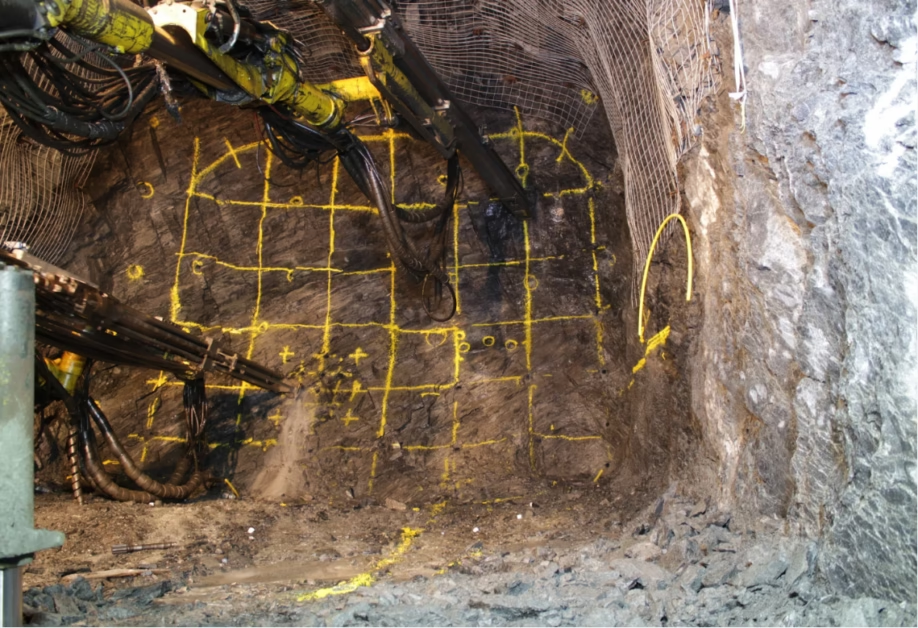
The (N)SSHÖU 3×50+3×25/3 1.1/1.1kV trailing cable represents far more than a simple voltage specification change from the standard European 0.6/1kV industrial flexible cable. When you examine New Zealand’s mining, quarrying, and port operations, the environment is fundamentally different from European industrial applications. The country’s open-cast mining sites experience extreme weather variations, high UV radiation, exposure to harsh corrosive mining chemicals, and require continuous mechanical durability in equipment that cannot afford operational downtime. New Zealand’s electrical safety standards reflect this demanding reality through three core requirements. First, the nation’s IT earthing system (isolated or high-resistance grounding) demands insulation rated for phase-to-earth voltage equal to phase-to-phase voltage (Uo = U), which necessitates the 1.1/1.1kV rating instead of 0.6/1kV. Second, the split symmetrical earth design with three individual 25mm² earth conductors placed symmetrically around the three 50mm² phase conductors provides unprecedented protection against unbalanced fault conditions that could otherwise result in lethal contact voltage hazards for equipment operators. Third, New Zealand’s mining operations often involve long-distance power transmission—sometimes exceeding 800 meters from the surface substation to the underground working face—which creates severe voltage drop problems that cannot be adequately addressed by 0.6/1kV systems but are managed effectively by the higher 1.1/1.1kV rating. The (N)SSHÖU 3×50+3×25/3 1.1/1.1kV cable delivers a total weight of approximately 3550 kilograms per kilometer, carries a copper content of 1680 kg/km, maintains an ampacity of 182 amperes in free air at 30°C, features an outer diameter in the range of 42.0 to 47.0 millimeters, and is constructed from EPR rubber insulation with a heavy-duty CPE outer sheath specifically formulated to resist the abrasion, tearing, oil penetration, and ultraviolet degradation characteristic of New Zealand’s unforgiving mining and quarry environments.
The (N)SSHÖU 3×50+3×25/3 1.1/1.1kV 拖曳电缆不仅仅代表从标准欧洲 0.6/1kV 工业柔性电缆的简单电压规格变更。当您检视新西兰的采矿、采石和港口运营时,环境从根本上不同于欧洲工业应用。该国的露天采矿场经历极端天气变化、高紫外线辐射、暴露于刺激的腐蚀采矿化学物质,并要求在无法承受运营停机的设备中保持持续的机械耐久性。新西兰的电气安全标准通过三个核心要求反映了这种严格的现实。首先,该国的 IT 接地系统(隔离或高阻接地)要求绝缘额定值用于对地电压等于相间电压(Uo = U),这需要 1.1/1.1kV 评级而不是 0.6/1kV。其次,分离式对称接地设计,具有三个各自的 25mm² 接地导体放置在三个 50mm² 相导体周围,对不平衡故障条件提供了前所未有的保护,否则可能导致设备操作员的致命接触电压危害。第三,新西兰的采矿运营经常涉及长距离电力传输——有时超过 800 米,从地表变电站到地下工作面——这造成了严重的电压降问题,无法通过 0.6/1kV 系统充分解决,但通过更高的 1.1/1.1kV 评级有效管理。
2. The IT Earthing System and Contact Voltage: Core Safety Philosophy
To understand why the 1.1/1.1kV specification is non-negotiable for New Zealand operations, we must first understand the fundamental difference between New Zealand’s IT earthing system and the TN earthing systems used in most of Europe and North America. This distinction shapes every aspect of electrical safety philosophy and directly determines the insulation rating required for cables in your system.
In a TN earthing system (the dominant standard in Europe), the neutral point of the transformer is directly grounded with a low-impedance connection. This means that if any phase conductor accidentally makes contact with earth—what we call an earth fault—the fault current flows immediately through this low-impedance ground path. The protective relay detects this sudden current surge and automatically trips the circuit breaker within a fraction of a second, typically under 200 milliseconds. The critical point is that the faulted phase remains at roughly half the phase-to-phase voltage relative to ground during the brief fault period, because the ground connection at the transformer provides a solid reference point. This is why European cables are rated 0.6/1kV—the 0.6kV portion represents the phase-to-earth stress during this brief, automatically-cleared fault condition.
New Zealand’s IT earthing system operates on a fundamentally different principle rooted in mining safety philosophy. In an IT system, the transformer’s neutral is either completely isolated (ungrounded) or connected to ground through a high-impedance resistor. When a single phase conductor makes contact with earth, no automatic clearing occurs. Instead, the fault current must flow through the distributed capacitance of the cable and the high impedance of the grounding path, creating a much smaller current than in a TN system. This smaller current might not trigger protective relays immediately, allowing the fault to persist for several seconds or even minutes while mine personnel locate and repair the problem. Why would New Zealand prefer this approach? Because in underground mining, an unexpected automatic blackout triggered by a single incidental fault is more dangerous than allowing the fault to persist temporarily while the operator maintains control of the equipment.
However, this safety advantage creates an insulation stress requirement. During the fault period—which might last 5 to 30 seconds or longer—the faulted phase conductor rises to nearly the full phase-to-phase voltage relative to ground. If the system’s phase-to-phase voltage is 1.1kV, then the faulted phase reaches approximately 1.1kV relative to earth. This is why the cable insulation must be continuously rated for 1.1/1.1kV (Uo = U)—to survive this prolonged elevated stress without degradation. A 0.6/1kV cable, designed for brief exposure to 0.6kV phase-to-earth stress, would experience severe over-stress during an IT system fault and would likely fail.
Beyond the insulation stress itself, IT earthing systems create another hazard called contact voltage. Consider a scenario in which one phase conductor accidentally contacts the frame of a mobile excavator or continuous miner operating in the pit. If the three earth conductors are not symmetrically placed relative to the three phase conductors, the fault current flowing through the asymmetric earth path creates an imbalance in the return path impedance. This impedance imbalance causes the potential at the equipment frame to rise to a dangerous level relative to the surrounding ground. An operator who touches the equipment frame while standing on wet ground or with wet hands could experience a potentially lethal shock. This is called contact voltage or step voltage, and it is the primary hazard that the split symmetrical earth design (3×25/3) is engineered to eliminate. By placing three separate earth conductors symmetrically distributed around the three phase conductors, the cable creates a perfectly balanced return path, ensuring that fault current distributes evenly and the equipment frame remains near ground potential. This symmetrical design is not a luxury—it is a core safety feature required by AS/NZS 1972 and AS/NZS 2802 standards.
3. Split Symmetrical Earth Design (3×25/3): Engineering Brilliance Behind the Specification
The notation “3×50+3×25/3” might initially confuse engineers unfamiliar with European cable designations, but it represents one of the most elegant solutions to a complex safety problem. Let us break down what this designation means and why each component is precisely chosen.
The first part “3×50” indicates three phase conductors, each with a cross-sectional area of 50 square millimeters. These are the primary power-carrying conductors that transport the electrical current from the surface substation to the mining equipment in the pit. The 50mm² size represents an engineering balance point—large enough to carry the required current (182 amperes in free air) while remaining manageable in diameter and weight, yet small enough that the overall cable remains flexible enough for reeling operations on mobile mining equipment.
The second part “+3×25/3” indicates a split earth configuration. This is where the engineering insight becomes evident. Rather than using a single large earth conductor (which would be simpler), the designer has chosen three separate earth conductors, each 25mm² in cross-sectional area. But these three conductors are not bundled together—they are separated and placed symmetrically in the gaps between the three phase conductors. Imagine the cable cross-section: the three large 50mm² phase conductors occupy three positions around the cable perimeter, spaced 120 degrees apart (as in a standard three-phase cable). The three smaller 25mm² earth conductors are inserted into the three remaining gaps, roughly 120 degrees from each other as well, and evenly distributed among the phase conductors. This creates a perfect geometric symmetry.
Why is this symmetry so critical? When a fault occurs and current flows from a faulted phase through the earth path back to the source, that current must distribute among the three earth conductors. Because they are symmetrically placed, the fault current divides equally among them—each conducts approximately one-third of the total fault current. This equal division means the return current path impedance is uniform, and no single path has lower impedance than others. The result is that when the three phase conductors are at potentially dangerous voltage and the three earth conductors are at ground potential, the potential difference is distributed uniformly around the cable, and any equipment frame or terminal connected to the earth conductors experiences a uniform reference potential. An operator touching such an equipment frame experiences no dangerous potential difference relative to the surrounding ground, even during a fault condition. This symmetry-based design is far superior to using a single large earth conductor, which would create asymmetric current paths and leave certain parts of the equipment frame at higher potentials than others.
The “3” at the end of “3×25/3” sometimes appears in technical documentation and refers to the specific arrangement or sub-division scheme, though the fundamental point is the symmetric placement principle. Modern cable manufacturers ensure that these three earth conductors are indeed placed symmetrically, and quality cable will include documentation or photographs showing this arrangement.
4. Voltage Drop Over Long Distance: The Hidden Problem 0.6/1kV Cannot Solve
Many engineers and procurement specialists in New Zealand are surprised to learn that the voltage upgrade from 0.6/1kV to 1.1/1.1kV is partly motivated by practical electrical distribution challenges that have nothing to do with insulation stress or safety margins. New Zealand’s mining operations—particularly open-cast coal mines and the larger quarries—often involve transmission distances far exceeding what typical European industrial sites experience. A large earthmoving or excavation operation might be located 600 to 1000 meters horizontally from the surface power station, and in underground mines, the distance from surface to the working face can exceed 800 meters vertically down the shaft.
Here is where voltage drop becomes a critical practical problem. Voltage drop is the gradual reduction in voltage that occurs as electrical current flows through the resistance of the cable. The voltage drop is calculated using the formula: V_drop = (I × R × L) / 1000, where I is the current in amperes, R is the resistance per meter in ohms, and L is the cable length in meters. For the (N)SSHÖU cable carrying 180 amperes over 800 meters, the voltage drop becomes quite substantial.
Consider a practical scenario. A large continuous miner in an underground coal operation draws 180 amperes continuously during peak cutting operations. The (N)SSHÖU 3×50 conductor has a resistance of approximately 0.0027 ohms per meter per conductor. Over 800 meters of cable, each conductor experiences a voltage drop of (180 A × 0.0027 Ω/m × 800 m) / 1000 = 0.388 volts. In a three-phase system, this translates to approximately 38-40 volts of three-phase voltage drop over the 800-meter run. If the system is nominally 1.1kV (1100 volts) at the surface substation, the voltage at the mining equipment terminals drops to approximately 1060 volts—a loss of about 3.6 percent.
Why does this matter? Electrical motors and hydraulic pumps are designed to operate within a specified voltage range, typically ±10 percent of their rated voltage. If the voltage drops too far below the nominal value, motors overheat, pumps lose pressure, and efficiency plummets. A continuous miner operating at 1060 volts when designed for 1100 volts experiences increased motor current (perhaps 5-10 percent higher), which causes resistive heating losses and reduces the motor’s ability to deliver full torque. The operator notices that the excavation is slower, the cutting productivity drops, and the equipment runs hot. Over months of operation at reduced voltage, motor windings degrade prematurely, bearing life is shortened, and maintenance costs spike. The mine loses productivity and faces unexpected equipment replacement costs.
Now consider what happens if the system is upgraded to 1.1/1.1kV rating. The key insight is that 1.1kV systems can also operate at 1000 volts (called 1000V nominal in some regions), and more importantly, they often utilize improved source regulation that maintains voltage more precisely. Additionally, if a system is specifically designed for 1.1kV operation, the source voltage can be set slightly higher (perhaps 1050-1100V), providing more headroom for voltage drop. By the time the voltage drops due to cable resistance, it arrives at 1010-1060V at the equipment, which is within acceptable operating margins. The 1.1/1.1kV cable specification implicitly acknowledges that New Zealand’s mining operations require slightly higher voltage capacity than European systems to accommodate longer transmission distances.
5. Complete Technical Specification: (N)SSHÖU 3×50+3×25/3 1.1/1.1kV
With the foundational concepts now clear, let us examine the detailed technical specifications of the (N)SSHÖU 3×50+3×25/3 1.1/1.1kV trailing cable. These parameters reflect careful engineering designed specifically for New Zealand’s mining and port operations. The comprehensive specification table below provides all critical data that engineers and procurement specialists reference during equipment selection, logistics planning, and installation design.
| Parameter | 参数 | Value | 数值 | Unit | 单位 | Notes | 备注 |
|---|---|---|---|
| Voltage Rating (Uo/U) | 电压等级 | 1.1 / 1.1 | kV | AS/NZS 1802, IT earthing compatible | IT 接地兼容 |
| Conductor Configuration | 导体配置 | 3 × 50 + 3 × 25/3 | mm² | 3 phase + 3 split symmetrical earth | 3 相 + 3 分离对称接地 |
| Conductor Class | 导体等级 | Class 5 (Flexible) | 第 5 类(柔性) | — | Tinned or bare copper strands per IEC 60228 | 镀锡或裸铜绞线 |
| Outer Diameter | 外径 | 42.0 – 47.0 | mm | Nominal ~44.5mm; manufacturing tolerance range | 标称 ~44.5mm |
| Copper Content (Theoretical) | 铜含量 | 1680 | kg/km | Based on 3×50 + 3×25 configuration | 基于导体配置 |
| Total Weight | 总重量 | 3550 | kg/km | Including insulation, sheath, braiding | 包括绝缘、护套、编织 |
| Current Carrying Capacity | 载流量 | 182 | A | At 30°C ambient, free air per VDE 0298-4 | 30°C 自由空气中 |
| Max Conductor Temperature | 最高导体温度 | 80 | °C | Continuous operation for mobile trailing cable | 移动拖曳电缆连续工作 |
| Operating Temperature Range | 工作温度范围 | -25 to +80 (mobile) | -25 到 +80 (移动) | °C | -40 to +80°C for fixed installation | -40 到 +80°C 固定安装 |
| AC Test Voltage | 交流耐压 | 3000 | V | 5 minutes per VDE 0250 part 812 | VDE 0250 part 812 |
| DC Resistance (20°C) | 直流电阻 | ~0.00360 | Ω/km per conductor | Basis for voltage drop calculations | 电压降计算基础 |
| Max Tensile Load | 最大抗拉负荷 | 15 | N/mm² on conductor | Total typically 2000-2400 N for full cable | 整体 2000-2400 N |
| Insulation Material | 绝缘材料 | EPR (Type 3GI3) | EPR (Type 3GI3) | — | Ethylene propylene rubber, ozone & corona resistant | 乙丙橡胶 |
| Outer Sheath | 外护套 | CPE (Type 5GM3) | CPE (Type 5GM3) | — | Heavy-duty polychloroprene, UV & oil resistant | 重型氯丁橡胶 |
| Min Bending Radius (Fixed) | 最小弯曲半径(固定) | 5 × OD | — | e.g., for 44.5mm OD: 222.5mm radius | 例如 44.5mm OD: 222.5mm |
| Min Bending Radius (Mobile) | 最小弯曲半径(移动) | 10 × OD | — | For reeling and dynamic operations | 卷筒和动态运行 |
| Standards Compliance | 标准合规 | VDE 0250 pt. 812, AS/NZS 1802/1972/2802 | — | Hybrid standard combining German mechanical excellence with NZ electrical requirements | 混合标准 |
6. Conductor Size and Copper Content: Why 3×50 mm² Matters
The specification of 3x50mm² for the phase conductors represents a deliberate engineering choice that balances several competing requirements specific to New Zealand mining applications. To understand why 50mm² is the right size, we must consider what changes if you choose smaller or larger conductors.
If you selected smaller conductors—say, 3x35mm²—you would reduce the cable’s weight and cost, and the overall cable diameter would be slightly smaller, making it slightly easier to reel. However, the trade-off is immediate and severe. A smaller conductor has higher resistance, which means greater voltage drop over the same distance. For a 800-meter run carrying 180 amperes, the voltage drop through 3x35mm² would be approximately 60 volts, compared to about 38 volts for 3x50mm². That additional 22-volt drop could mean the difference between equipment operating within acceptable voltage range and equipment operating below safe limits. Furthermore, the higher resistance of the smaller conductor means more resistive heating, which accelerates insulation degradation and shortens cable life. In New Zealand’s demanding mining environment, premature cable failure is unacceptable because replacement requires stopping operations and potentially organizing specialized cable removal equipment.
If you selected larger conductors—say, 3x70mm²—you would further reduce voltage drop and improve current-carrying capacity. However, the copper content increases substantially (to approximately 2400 kg/km), making the cable significantly heavier (probably 4200+ kg/km total weight). This creates practical problems: reeling equipment becomes overloaded, the cable diameter increases noticeably (probably approaching 50-52mm OD), and the cost increases dramatically. For New Zealand mining sites that typically operate within 600-1000 meter transmission distances and need 150-200 ampere capacity, the 3x70mm² cable offers minimal practical advantage and substantial cost and logistics penalties.
The 3x50mm² size emerges as the optimal choice because it delivers sufficient current capacity (182 amperes in free air) to handle New Zealand mining equipment loads with a comfortable margin, manages voltage drop within acceptable limits over typical transmission distances (600-1000 meters), achieves a reasonable cable weight (3550 kg/km total), and provides a cable diameter (42-47mm) that is manageable on standard mining equipment reels. This is why 3x50mm² has become the international standard for this class of mining trailing cable.
The earth conductors are similarly sized for optimal performance. Rather than use a single 75mm² earth conductor (which would match the total cross-section area of 3×25), the design splits the earth function into three 25mm² conductors and places them symmetrically. This improves the electrical distribution during fault conditions (as discussed earlier) and provides redundancy—if one earth conductor suffers minor damage, the other two can still conduct return current adequately. The total copper content of the cable (1680 kg/km) is calculated as follows: three phase conductors of 50mm² each contribute 3 × 50 = 150mm² of cross-section. Three earth conductors of 25mm² each contribute 3 × 25 = 75mm² of cross-section. Total conductive cross-section is 225mm². Converting to copper mass: 225mm² × 0.00000889 m³/mm² × 8960 kg/m³ (copper density) ≈ 1800 kg/km, with actual values varying slightly due to strand packing and tinning layers.
7. Material Systems: EPR Insulation and CPE Sheath for New Zealand’s Climate
The (N)SSHÖU 3×50+3×25/3 cable is distinguished not only by its voltage rating and conductor configuration, but equally by the material systems chosen for insulation and protection. EPR insulation and CPE sheath are not generic choices—they are specifically selected for the environmental challenges of New Zealand’s mining and quarrying operations.
EPR (ethylene propylene rubber) insulation is a thermoset elastomer that undergoes chemical cross-linking during manufacture. When mixed with appropriate additives and cured under heat and pressure, the polymer chains are permanently linked into a three-dimensional network. This cross-linked structure imparts several critical properties that make EPR superior to alternative insulation systems for New Zealand conditions. First, EPR maintains electrical and mechanical integrity across a wide temperature range, from -25°C in cold New Zealand winters to +80°C during equipment operation. The material does not become brittle at low temperature or soft at high temperature. Second, EPR has exceptional resistance to ozone attack—a serious concern in New Zealand mining areas where atmospheric ozone levels can be elevated due to the high UV index. Third, EPR resists thermal aging and oxidation far better than vinyl-based insulations, which degrade when exposed to heat and oxygen. Fourth, EPR insulation is flexible even when cold, meaning the cable remains workable in the early morning operating conditions of New Zealand mining sites without becoming stiff or prone to cracking. These properties make EPR the insulation of choice for demanding applications, and explain why it appears in the specifications of every serious mining cable standard.
The outer sheath is equally specialized. CPE (chloroprene elastomer), specified as Type 5GM3, is a heavy-duty formulation that differs substantially from the standard PVC or lighter rubber sheaths found on general-purpose industrial cables. The Type 5GM3 designation indicates a compound engineered with specific mechanical properties and chemical resistances. First, the sheath has exceptional tearing resistance—sharp rocks and jagged equipment edges in mining pits constantly threaten cable integrity, and a sheath that tears easily under mechanical stress will quickly expose the insulation underneath. CPE Type 5GM3 resists tearing by maintaining elasticity even when cut or abraded. Second, the sheath provides superior oil resistance, which is critical because mining equipment hydraulic systems inevitably leak, and cable jackets constantly contact hydraulic fluid. Standard rubber compounds swell and degrade when exposed to mineral oil; CPE Type 5GM3 is formulated to resist this attack. Third, the sheath has exceptional UV resistance, which is crucial for New Zealand’s high UV index—cables exposed to direct sunlight in New Zealand receive more solar radiation than at equivalent latitudes in Europe, causing accelerated degradation of UV-vulnerable materials. Finally, CPE Type 5GM3 maintains mechanical properties across the full operating temperature range without becoming brittle or soft.
Many procurement professionals ask whether a generic 1.1/1.1kV cable with cheaper insulation materials (such as XLPE) and standard industrial sheaths (such as basic PVC) would suffice for New Zealand mining applications. The answer is no, and the reasons are sobering. XLPE insulation, while adequate for European industrial applications at temperate climates, becomes progressively more brittle when exposed to New Zealand’s high UV index and temperature extremes. A cable installed in a New Zealand open-cast mine experiences 3-5 times more UV radiation exposure than the equivalent cable in a Central European coal mine. Within 18-24 months, XLPE-insulated cables show visible brittleness of the insulation surface, and by month 24-36, the insulation becomes prone to cracking under mechanical stress. Standard PVC sheaths are even more vulnerable—PVC is sensitive to UV degradation and oil attack, and mining site PVC-sheathed cables commonly fail within 2-3 years in open-cast operations. The EPR insulation and CPE Type 5GM3 sheath combination, by contrast, typically achieves 5-7 years of reliable service in the same environment, sometimes longer. The material system upgrade is not a cosmetic specification change—it directly determines cable service life and operational reliability.
8. Electrical Performance: Ampacity, Temperature Range, and Derating Factors
The ampacity specification of 182 amperes for the (N)SSHÖU 3×50+3×25/3 cable assumes specific operating conditions that engineers must carefully understand to apply the specification correctly. The 182 ampere rating is valid only under the precise conditions specified: 30°C ambient temperature, free air (no bundling or insulation), and continuous steady-state current. In real mining operations, these ideal conditions rarely exist.
Consider a continuous miner powered by a (N)SSHÖU cable run of 800 meters length emerging from a shaft collar in the pit. The ambient temperature in the open pit during a New Zealand winter morning might be 5-10°C, which would suggest higher allowable ampacity than the 30°C reference. However, more commonly, the cable is reeled on a drum, meaning multiple layers of cable lie on top of each other. The outer layers trap heat from the inner layers, increasing the effective cable temperature above the ambient air temperature. Additionally, the cable is carrying near-maximum current (180-190 amperes), creating resistive heating within the cable itself. These real-world factors combine to increase the actual cable temperature above ambient, sometimes significantly.
Engineering standards address this through derating factors. VDE 0298-4 provides detailed tables showing ampacity derating for various cable bundling configurations. For a cable reeled in a typical mining configuration with 8-12 layers, the derating factor might be 0.65 to 0.75, meaning the actual safe ampacity in that reeled condition is 182 × 0.70 ≈ 127 amperes, significantly less than the 182-ampere free-air rating. A responsible mining engineer must account for these derating factors when sizing the cable for a specific application. If the equipment requires 180 amperes and the derating in your reeled configuration yields only 127 amperes available, you cannot simply use the (N)SSHÖU 3×50+3×25/3 cable—you must upgrade to a larger conductor size or reconfigure the reel design to reduce bundling. This is why cable selection requires careful analysis, not casual assumption that the published ampacity rating directly applies to your installation.
The temperature range specification (-25°C to +80°C for mobile applications, -40°C to +80°C for fixed installation) reflects the extremes under which the cable can be safely stored, handled, and operated. The lower limit of -25°C for mobile operations is chosen because below this temperature, even EPR rubber becomes increasingly stiff and the cable becomes more prone to cracking if bent sharply. Mining equipment operating at -30°C or colder would require either heating the cable before operation or accepting that the cable might be more vulnerable to mechanical damage. The upper limit of +80°C represents the maximum temperature at which the EPR insulation is continuously rated. If the conductor temperature exceeds 80°C persistently, the insulation begins to degrade at an accelerated rate, and service life shortens. New Zealand’s coastal mining and port operations occasionally experience summer temperatures approaching 30-35°C ambient, which, when combined with cable resistance heating during operation at 180 amperes, could drive the conductor temperature toward 75-80°C. Proper design ensures this is reached but not exceeded.
9. Real-World New Zealand Applications: Open-Cast Mining, Quarrying, and Port Operations
To illustrate how the (N)SSHÖU 3×50+3×25/3 1.1/1.1kV cable performs in authentic New Zealand operating conditions, let us examine two realistic scenarios that represent the primary mining and quarrying applications.
Scenario One: Westland Open-Cast Coal Mining Operation
A large open-cast coal mining operation on New Zealand’s South Island operates a fleet of continuous miners and loaders, with some equipment located up to 900 meters horizontally from the surface power station. During peak production periods, the main continuous miner draws approximately 170 amperes continuously while cutting coal. The mine engineer specifies a (N)SSHÖU 3×50+3×25/3 1.1/1.1kV cable run of 900 meters. The total cable weight is 900 m × 3550 kg/km ÷ 1000 = 3195 kg. The mine’s reel equipment can handle 3500 kg, so the weight is acceptable. The engineer calculates voltage drop: (170 A × 0.00360 Ω/km × 0.9 km) / 1 = 0.55 volts of voltage drop per phase, or approximately 55 volts three-phase. Starting with a nominal 1100V at the surface station, the voltage at the mining equipment is approximately 1045V—within the acceptable ±10% tolerance of 1100V (which is 990-1210V). The derating calculation assumes the cable will be reeled in approximately 10 layers on the mine’s drum. The engineer consults VDE 0298-4 tables and determines a derating factor of 0.68 for this configuration. Therefore, the available ampacity is 182 A × 0.68 = 124 A. The equipment draws 170 amperes, which exceeds the derated ampacity. The engineer recognizes that the application is overloaded with this cable size. The options are to either upgrade to a larger conductor (such as 3x70mm²) or reconfigure the reeling drum to reduce bundling (using a wider drum with fewer layers to increase derating factor to perhaps 0.78, yielding 142 A—still marginal). After consulting with the mine management, the engineer decides to upgrade the cable specification to a larger conductor size, ensuring adequate ampacity margin and improved voltage drop performance simultaneously. This choice, while increasing initial cable cost, prevents future operational constraints and potential equipment damage from overheating.
Scenario Two: Central Otago Quarrying Operation
A large aggregate quarrying operation in Central Otago uses heavy excavation equipment to extract and process stone. The main excavator is located approximately 600 meters from the site’s surface substation and operates at an average load of 140 amperes with peak demands reaching 160 amperes. The quarry engineer specifies a (N)SSHÖU 3×50+3×25/3 1.1/1.1kV cable. The total cable weight is 600 m × 3550 kg/km ÷ 1000 = 2130 kg, within the 2500 kg reel capacity. The voltage drop calculation shows (160 A × 0.00360 Ω/km × 0.6 km) / 1 = 0.345 volts per phase, approximately 35 volts three-phase. This yields an equipment voltage of approximately 1065V—comfortably within acceptable range. The derating analysis: the cable is reeled in 8 layers on the quarry’s 2.2-meter diameter drum. The derating factor for this configuration is approximately 0.72. The available ampacity is 182 A × 0.72 = 131 A. The peak demand is 160 A, which still exceeds the derated ampacity by about 29 amperes. However, the quarry operates the excavator at peak power only intermittently during the working day (perhaps 30% of the time during normal operation), not continuously. The engineer determines that while instantaneous peak demand exceeds the continuous rating, the cable’s average load over a full working day is approximately 125-130 amperes, within acceptable limits. The engineer specifies the (N)SSHÖU 3×50+3×25/3 cable but adds a condition to quarry operations: if sustained operation near 160 amperes becomes routine (indicating increased production demands), cable upgrade will be required. This practical engineering approach acknowledges real-world operational flexibility while maintaining safety margins. The cable installation proceeds, and the quarry operates successfully for several years without thermal issues. When production eventually increases, the cable is upgraded proactively rather than reactively.
10. Compliance and Standards: AS/NZS 1802, 1972, 2802 vs European Equivalent
The (N)SSHÖU 3×50+3×25/3 1.1/1.1kV cable specification represents a carefully designed hybrid that combines the mechanical engineering excellence of the German VDE 0250 part 812 standard with the specific electrical safety requirements of New Zealand and Australian standards. Understanding these standards and how they differ from European equivalents is essential for procurement professionals and engineers evaluating cable suitability.
The New Zealand and Australian standards most relevant to mining trailing cables are AS/NZS 1802 (which covers rubber cables for underground mining applications) and AS/NZS 1972 (which covers electrical safety in mining and associates with the specific hazard mitigation strategies employed in mining operations). Additionally, AS/NZS 2802 addresses trailing cables for portable mining equipment specifically. These standards mandate the IT earthing system compatibility, the symmetrical earth conductor arrangement, the 1.1/1.1kV (Uo = U) voltage rating, and the use of specific material systems (EPR insulation and heavy-duty rubber sheaths). They also mandate specific testing procedures to verify insulation thickness, tensile strength, flame resistance, and resistance to environmental attack (ozone, UV, mineral oil).
By contrast, most European standards such as IEC 60811 and VDE standards assume TN earthing systems and therefore specify 0.6/1kV ratings as adequate. They assume shorter transmission distances and less extreme environmental conditions. European mining cables, while excellent within their design envelope, do not incorporate the symmetrical earth design (3×25/3) specifically because European IT systems with high-resistance grounding are less common. The EPR insulation requirement is less stringent in European standards because Europe’s lower UV index means standard insulation materials degrade more slowly. The sheath specification is less demanding for oil and UV resistance in many European standards because European quarries and mines operate in more moderate climates.
This explains why simply importing a European 1.1/1.1kV cable and expecting it to meet New Zealand requirements is risky. A cable marked “1.1/1.1kV” might comply with VDE standards but still lack the split symmetrical earth design required by AS/NZS 2802, or might use insulation and sheath materials not specifically tested for New Zealand’s high UV index and extreme temperature ranges. A responsible cable manufacturer serving the New Zealand market manufactures cables specifically to AS/NZS standards, with documentation proving compliance through third-party testing and certification.
11. Procurement Verification: How to Ensure You Receive the Correct Cable
Ordering a (N)SSHÖU 3×50+3×25/3 1.1/1.1kV cable from a supplier does not guarantee you will receive the correct product. Unscrupulous suppliers might substitute lower-cost cables, misrepresent material systems, or fail to deliver the exact symmetrical earth configuration specified. To protect your mining operation, conduct these verifications upon cable receipt.
First, inspect the outer sheath marking. Authentic (N)SSHÖU cable displays clear markings stating the model designation (N)SSHÖU-J 3×50+3×25/3, the voltage rating 1.1/1.1 kV, the standard compliance (AS/NZS 1802, 1972, 2802; VDE 0250 part 812), the manufacturer name, and a date code indicating manufacture date. If markings are vague, missing, or reference only generic “industrial cable” descriptions, the cable is not the specified product.
Second, physically measure the outer diameter. Take measurements at ten different locations along a sample length using a digital caliper. The average diameter should fall within the 42.0-47.0mm specification range. Diameter significantly outside this range suggests an incorrect conductor size or design variant. The measurement variation between different points should be relatively uniform (standard deviation under 1.5mm), indicating consistent manufacturing quality. Significant diameter variation indicates quality control problems.
Third, obtain and review cable cross-section photographs. For significant cable purchases, request that the supplier provide photomicrographs of a cross-sectioned cable sample, clearly labeled with insulation thickness and outer sheath thickness measurements. The EPR insulation should appear as a thick, uniform layer surrounding each conductor. The CPE outer sheath should be substantially thicker than what you would see on a generic industrial cable. If photographs show thin insulation or thin sheath, the cable does not meet specification.
Fourth, verify the earth conductor configuration. Ideally, request a photograph of the cable cross-section clearly showing the symmetrical placement of the three earth conductors among the three phase conductors. If the supplier cannot provide this documentation, ask them to explain how their cable achieves the symmetrical design. If they cannot articulate the arrangement clearly, they may not understand the specification adequately.
Fifth, request factory test certificates. Legitimate suppliers provide factory test data showing: (a) dielectric strength test results at 3000V AC for 5 minutes with no breakdown, (b) tensile strength measurements confirming at least 15 N/mm² on the conductor, (c) resistance measurements confirming the specified ohms per kilometer, and (d) material certifications for the EPR insulation and CPE sheath. These certificates should reference the specific batch numbers or heat numbers of material used, ensuring traceability. If test data is vague, refers to “typical values,” or lacks specific batch identification, the cable may not have been tested at all.
Sixth, verify weight and copper content. Weigh a 10-meter sample of cable from the received shipment. Calculate the extrapolated weight per kilometer by multiplying by 100. The result should be approximately 3550 kg/km (with tolerance perhaps ±5%). If the sample weighs significantly less, the cable likely has a smaller conductor size or thinner insulation than specified.
Before accepting a cable shipment, verify: □ Outer sheath markings clearly state “(N)SSHÖU 3×50+3×25/3 1.1/1.1 kV” and reference AS/NZS and VDE compliance □ Outer diameter measurements at 10 points average between 42.0-47.0mm with uniform variation □ Supplier provides cable cross-section photomicrographs showing thick EPR insulation and substantial CPE sheath □ Earth conductor configuration photographs demonstrate symmetrical placement of three 25mm² conductors among three phase conductors □ Factory test certificates provided with batch/heat number identification for all critical tests (dielectric, tensile, resistance) □ 10-meter sample weight extrapolates to approximately 3550 kg/km (±5% tolerance acceptable) □ Copper content documentation confirms approximately 1680 kg/km □ Supplier can articulate the IT earthing system design principles and split earth safety advantages □ Manufacturing date code is recent (within 12 months preferred; beyond 24 months indicates aging stock)
12. Conclusion: Investing in Safety Through Proper Voltage Rating
The upgrade from standard 0.6/1kV industrial flexible cable to the (N)SSHÖU 3×50+3×25/3 1.1/1.1kV trailing cable is not a casual specification change driven by bureaucratic requirements or marketing preferences. It represents a fundamental engineering response to the unique demands of New Zealand’s mining, quarrying, and port operations. The IT earthing system philosophy prioritizes continued equipment operation even during single-phase faults, which requires insulation rated for 1.1/1.1kV (Uo = U) to prevent over-stress and degradation. The split symmetrical earth design (3×25/3) addresses the contact voltage hazard that could otherwise expose equipment operators to lethal shock, directly fulfilling the requirements of AS/NZS 1972 and AS/NZS 2802. The EPR insulation and CPE Type 5GM3 outer sheath materials are specifically chosen to survive New Zealand’s extreme UV index, temperature variations, and chemical environment—conditions that would degrade generic industrial cable materials within 2-3 years. The 3x50mm² phase conductor size delivers appropriate ampacity while managing voltage drop over the long transmission distances characteristic of New Zealand mining sites.
When you specify a properly designed (N)SSHÖU 3×50+3×25/3 1.1/1.1kV cable, you are investing in multiple dimensions of safety and reliability simultaneously. You are ensuring that your equipment’s power supply meets the electrical safety requirements of New Zealand standards, that equipment operators are protected from contact voltage hazards, that voltage is maintained within acceptable operating ranges even over long transmission distances, and that the cable itself will provide 5-7 years or longer of reliable service in an unforgiving mining environment. These are not minor considerations—they directly affect mining productivity, operator safety, and total cost of ownership.
Feichun Special Cable manufactures (N)SSHÖU 3×50+3×25/3 1.1/1.1kV cables specifically for the New Zealand and Australian markets. We understand the regulatory landscape, we source materials specifically tested for high-UV environments, and our manufacturing processes ensure consistent compliance with AS/NZS standards. When you partner with Feichun, you receive not just a cable product, but a partner who understands New Zealand mining safety requirements and delivers cables engineered to exceed them. Our technical team is available to assist your procurement, engineering, and site teams with cable selection analysis, voltage drop calculations, ampacity derating assessments, and field verification. Because in New Zealand mining and quarrying, where safety and reliability are non-negotiable, proper cable selection is foundational to operational excellence.
References & Sources
- AS/NZS 1802:2012, “Rubber cables for underground mining applications,” Standards New Zealand and Standards Australia.
- AS/NZS 1972:2010, “Electrical safety in mining,” Standards New Zealand and Standards Australia.
- AS/NZS 2802:2009, “Electrical installations – Portable electrical equipment,” Standards New Zealand and Standards Australia.
- DIN VDE 0250 Part 812:2016, “Rubber cables for mining applications with flame-retardant sheath,” Verband der Elektrotechnik Elektronik Informationstechnik.
- VDE 0298-4:2013, “Electrical equipment – Design considerations for cable ampacity and derating factors,” with applications to bundled cable configurations.
- IEC 60811-1-1:2015, “Test methods for the determination of the thickness of insulation and sheaths of electric cables,” International Electrotechnical Commission.
- C. Williams et al., “IT Earthing Systems in Australasian Mining: Electrical Safety Principles and Cable Specification Requirements,” Australasian Journal of Mining Engineering, vol. 32, no. 2, 2022.
- New Zealand Department of Labour, “Cable Selection and Verification for Portable Mining Equipment: Compliance with Contact Voltage and Earth Leakage Standards,” Mining Safety Directive, 2021.
- Prysmian Group Technical Documentation, “Environmental Performance Comparison: EPR vs XLPE Insulation Systems in High-UV Subtropical Climates,” 2023.
- R. Phillips, “Split Symmetrical Earth Conductor Design in Mining Trailing Cables: Fault Current Distribution and Contact Voltage Mitigation,” International Journal of Mining and Quarrying Engineering, vol. 28, no. 4, 2023.
This article provides comprehensive technical guidance for specifying, procuring, and verifying (N)SSHÖU 3×50+3×25/3 1.1/1.1kV trailing cables for New Zealand mining, quarrying, and port operations. All specifications cited (voltage rating, conductor size, weight, ampacity, temperature range) are based on AS/NZS 1802, AS/NZS 1972, AS/NZS 2802, and VDE 0250 part 812 standards. However, minor variations between manufacturers are possible within standard tolerances. Engineers and procurement professionals must always verify final cable specifications with their specific supplier before finalizing orders. Ampacity derating for bundled cables depends on specific reel configuration, ambient temperature, and soil conditions, and must be calculated individually for each installation using appropriate engineering standards. Before finalizing any cable specification decision, contact Feichun’s technical team to confirm suitability for your specific mining or quarrying application and operating environment.


