
Inductive Coupling vs. Direct Connection — A Comparative Technical Analysis for Heavy-Duty Reeling & Trailing Cables
电源方案:(N)TSCGEH3S 电缆中电致发光(EL)线的供电方式 —— 感应耦合与直接连接技术对比分析
Power Source: How Are the Electroluminescent (EL) Strings in (N)TSCGEH3S Powered?
Inductive Coupling vs. Direct Connection — A Comparative Technical Analysis for Heavy-Duty Reeling & Trailing Cables
电源方案:(N)TSCGEH3S 电缆中电致发光(EL)线的供电方式 —— 感应耦合与直接连接技术对比分析
1. Introduction to the (N)TSCGEH3S Cable Designation
The type designation (N)TSCGEH3S follows the German DIN VDE cable nomenclature system, which uses sequential letters to encode every aspect of a cable’s construction, insulation material, and intended service conditions. Under DIN VDE 0292, the leading N (in parentheses) indicates the cable is manufactured to a recognized VDE type standard with permissible manufacturer variations, while subsequent characters specify the conductor type, shielding, elastomeric insulation, and special functional elements embedded in the cable assembly.
型号标识 (N)TSCGEH3S 遵循德国 DIN VDE 电缆命名规范,每个字母依次编码了电缆的结构、绝缘材料及适用工况。括号中的”N”表示该型号依据 VDE 标准制造,允许制造商做出一定的变型设计。
In this designation, the segment H3S is of particular interest: it specifies the inclusion of electroluminescent (EL) indicator elements — typically phosphor-coated wires integrated into the cable assembly — and the method by which they are energized. The “3” typically indicates the number of EL conductor strands, while the “S” refers to a specific sheath configuration for the luminescent layer. Understanding how these EL elements receive power is critical for safe cable design, operational reliability, and compliance with standards such as DIN VDE 0250 and IEC 60245.
“H3S”段尤为关键:它指定了电缆中嵌入的电致发光(EL)指示元件——通常为磷光粉涂覆导线——的数量及护套结构。理解 EL 元件的供电方式对于电缆设计安全、运行可靠性以及标准合规性(如 DIN VDE 0250、IEC 60245)至关重要。
| Letter 字母 | Meaning (DIN VDE 0292) 含义 | Detail 说明 |
|---|---|---|
| (N) | VDE-recognized type with variation 符合VDE标准的认可型号 | Parentheses allow manufacturer-specific construction alternatives |
| T | Drum reeling / trailing service 卷筒/拖拽用途 | Designed for cyclic winding on cable drums |
| SC | Shielded, concentric copper screen 铜编织屏蔽层 | Provides EMI shielding and ground fault protection |
| G | Flexible elastomeric (rubber) construction 柔性弹性体结构 | Typically EPR or EVM compound per DIN VDE 0207 |
| E | Earth/protective conductor present 含保护接地芯 | Integrated PE conductor for safety grounding |
| H3 | 3× EL (electroluminescent) filaments 三根EL发光丝 | Phosphor-coated strands embedded in cable interstices |
| S | Special outer sheath 特殊外护套 | Heavy-duty polychloroprene (PCP) or TPU jacket |
2. Fundamentals of EL Wire Technology
Electroluminescent wire consists of a solid copper core coated in a phosphor compound. When an alternating electric field is applied across the phosphor layer, electrons are excited to a higher energy state; upon returning to their ground state, they emit visible photons — a phenomenon first documented by Georges Destriau in 1936. Around the phosphor-coated core, one or two very fine “angel hair” copper wires are spiral-wound to form the second electrode, creating a coaxial capacitor structure. An outer transparent or colored PVC sheath provides mechanical and moisture protection.
电致发光导线由涂覆磷光粉的实心铜芯构成。对磷光层施加交变电场时,电子被激发至高能态,回落时释放可见光子。该现象由 Georges Destriau 于1936年首次记录。围绕磷光涂覆铜芯,缠绕一至两根极细的铜丝构成第二电极,形成同轴电容器结构。
Crucially, EL wire operates exclusively on alternating current (AC). With direct current (DC), the phosphor would emit light only momentarily as current passes in one direction, ceasing almost immediately. AC continuously reverses polarity, ensuring sustained excitation. A typical operating frequency range is 400 Hz – 4 kHz, with driving voltages of 80 – 120 VAC depending on wire length and desired luminance. Brightness is proportional to both voltage amplitude and frequency; however, higher frequencies accelerate phosphor degradation, reducing operational half-life.
关键点:EL 线仅在交流电(AC)下工作。直流电只能产生瞬间发光。典型工作频率为 400 Hz – 4 kHz,驱动电压为 80 – 120 VAC。亮度与电压幅值和频率成正比,但更高频率会加速磷光粉老化。
| Parameter 参数 | Typical Value 典型值 | Unit 单位 | Note 备注 |
|---|---|---|---|
| Operating Voltage 工作电压 | 80 – 120 | VAC | Depends on wire length & inverter |
| Operating Frequency 工作频率 | 400 – 4,000 | Hz | Higher = brighter but shorter life |
| Current Draw 电流消耗 | ~10 | mA/m | Low power consumption per meter |
| Luminance (at 1.5 kHz / 90 V) 亮度 | ~32 | cd/m² | High-brightness variant |
| Half-Life (50 % brightness) 半衰期 | ~3,000 | hours | Continuous operation |
| Wire Diameter 线径 | 2.3 – 5.0 | mm | Standard variants |
| Capacitance (typical) 电容 | ~6 – 12 | nF/m | Determines LC resonance tuning |
Because EL wire behaves electrically as a distributed capacitor, the driver circuit must supply reactive power. Using an inductive (coiled) transformer to form a tuned LC oscillator with the wire’s inherent capacitance is an extremely efficient approach. As noted in the IEEE literature on resonant power conversion, this configuration can drive up to 100 meters of EL wire from a pair of AA batteries for several hours.
由于EL线在电气上表现为分布式电容器,驱动电路须提供无功功率。利用电感变压器与线缆固有电容构成LC谐振振荡器是一种高效率的方案。
3. Method A — Direct Electrical Connection (Galvanic)
3.1 Operating Principle 工作原理
In a direct connection topology, the EL filaments embedded within the (N)TSCGEH3S cable assembly receive power through dedicated conductor pairs that run the entire length of the cable alongside the main power cores and control conductors. A compact AC inverter module — typically mounted at the cable drum termination point or within the cable junction box — converts available DC or low-frequency AC into the high-frequency, elevated-voltage AC signal (~100 VAC @ 1–2 kHz) required by the phosphor coating. The galvanic (ohmic) path from inverter to EL wire is continuous and unbroken, meaning the drive signal is transmitted conductively through physical wire contact.
在直接连接拓扑中,嵌入 (N)TSCGEH3S 电缆中的 EL 发光丝通过专用导体对获得电力,该导体对与主电力芯及控制导线沿全长并行敷设。一个小型 AC 逆变器模块将可用的直流或低频交流电转换为 EL 磷光层所需的高频高压交流信号(约 100 VAC @ 1–2 kHz)。
3.2 Circuit Architecture 电路架构
The inverter circuit commonly employs a cross-coupled transistor oscillator topology (also known as a Royer oscillator) with a small ferrite-core transformer. The primary winding is driven by the transistor pair, and the secondary winding outputs the required high-voltage AC. For cable-integrated EL applications, a single-chip switched-capacitor inverter IC (such as the Microchip HV857 or similar) can also be used, offering a very compact footprint suitable for in-cable or in-connector mounting. The EL wire’s capacitance and the transformer inductance form a resonant tank circuit, enabling high electrical efficiency — often exceeding 85 % power conversion at the optimal resonant frequency.
逆变器电路通常采用交叉耦合晶体管振荡器(Royer 振荡器)拓扑,配合小型铁氧体磁芯变压器。EL 线的电容与变压器电感构成谐振回路,使电能转换效率通常可超过 85%。
3.3 Advantages & Limitations 优缺点
The primary advantage of galvanic connection is simplicity and reliability: no electromagnetic coupling gaps are involved, so the power transfer is inherently stable and unaffected by cable bending radius, environmental debris, or air-gap variation. The inverter output voltage and frequency can be precisely controlled, yielding consistent EL brightness along the entire cable length. However, this method requires additional dedicated conductors within the cable cross-section, increasing manufacturing complexity, overall cable diameter, and potentially reducing bending flexibility — a critical consideration for drum reeling applications where minimum bending radii per DIN VDE 0298 Part 3 must be maintained.
直连方式的主要优点是简单可靠,不存在电磁耦合间隙,功率传输稳定。缺点是需要额外的专用导体,增加了电缆截面和直径,可能降低弯曲灵活性——这在卷筒应用中是关键考量。
4. Method B — Inductive (Electromagnetic) Coupling
4.1 Operating Principle 工作原理
Inductive coupling eliminates the need for a dedicated physical conductor to power the EL elements. Instead, the existing power cores of the (N)TSCGEH3S cable — which carry substantial AC current during normal crane or reeling-system operation — serve as the primary winding of a loosely-coupled transformer. The EL wire’s own spiral-wound angel-hair conductors, wrapped helically around the phosphor-coated core, act as a secondary pickup coil. The alternating magnetic field generated by current flow in the adjacent main power conductors induces a voltage across the EL wire’s spiral electrode, sufficient to excite the phosphor and produce visible light.
感应耦合无需专用物理导体为 EL 元件供电。电缆中现有的电力芯线——在正常起重机或卷筒系统运行时承载大量交流电流——充当松耦合变压器的初级绕组。EL 线自身的螺旋缠绕细铜丝充当次级拾取线圈。主电力导体中的交变电流产生的磁场在 EL 线的螺旋电极上感应电压,足以激发磷光粉并产生可见光。
4.2 Electromagnetic Coupling Mechanism 电磁耦合机制
According to Faraday’s law of electromagnetic induction, the voltage induced in the EL pickup coil is proportional to the rate of change of magnetic flux linkage (V = −N × dΦ/dt). In a cable environment, the coupling coefficient is inherently low due to the lack of a ferromagnetic core concentrating the field, the relatively small cross-sectional area of the EL coil, and the geometric separation between the power core surface and the EL filament within the cable interstices. To compensate, the system leverages the power conductor’s operating frequency (typically 50/60 Hz mains) and the substantial current magnitude (tens to hundreds of amperes in crane applications) to generate a sufficiently strong alternating field.
根据法拉第电磁感应定律,EL 拾取线圈中的感应电压与磁通量变化率成正比(V = −N × dΦ/dt)。在电缆环境中,由于缺少铁磁芯集中磁场,耦合系数较低。系统利用电力导体的工作频率(50/60 Hz)及大电流(起重机应用中可达数十至数百安培)来产生足够强的交变磁场。
Research on inductive power transfer (IPT) systems — such as the work by the Auckland UniServices team documented in patent WO1998/050993A1 — has demonstrated that EL panels and wires can be powered across extended air gaps using resonant intermediate loops. The patent describes powering EL displays at 1.2 kHz with DC power collected by a secondary pickup coil tuned to a system frequency of 15 kHz, using inductive coupling from a primary conductor. This principle is directly applicable to the cable-internal scenario in (N)TSCGEH3S where the power cores function as the primary conductor.
奥克兰大学团队的感应电力传输(IPT)研究(专利 WO1998/050993A1)已证明,可通过谐振中间环路在较大气隙上为 EL 面板和导线供电。该原理可直接应用于 (N)TSCGEH3S 电缆内部场景。
4.3 Advantages & Limitations 优缺点
The inductive approach offers an elegant solution: no additional conductors are needed, reducing cable diameter, weight, and cost while preserving mechanical flexibility. The EL elements are inherently electrically isolated from the main power circuit, enhancing safety margins. However, the method introduces variability: EL brightness depends on the load current flowing through the power cores, meaning the illumination intensity will fluctuate with operational load changes. During no-load or low-load periods, the induced voltage may fall below the phosphor’s threshold voltage, causing the EL elements to dim or extinguish — a significant operational consideration in crane applications where current varies with lifting cycles.
感应耦合的优点:无需额外导体,减小电缆直径、重量和成本,同时保持机械柔韧性。EL 元件与主电力回路天然电气隔离,提高安全裕度。缺点:EL 亮度取决于电力芯的负载电流,在空载或轻载时亮度可能不足。
5. Head-to-Head Comparison: Electrical Parameters
| Parameter 参数 | Direct Connection 直接连接 | Inductive Coupling 感应耦合 |
|---|---|---|
| Power Source 电源 | Dedicated inverter + conductor pair 专用逆变器+导体对 | Parasitic from main power cores 从主电力芯寄生获取 |
| Drive Voltage 驱动电压 | 80 – 120 VAC (regulated) | Variable, load-dependent 可变,负载相关 |
| Drive Frequency 驱动频率 | 1 – 4 kHz (optimized) 可优化 | 50 / 60 Hz (mains) 工频 |
| Brightness Stability 亮度稳定性 | High — constant output 高——恒定输出 | Variable — tracks load current 可变——跟随负载电流 |
| Additional Conductors 额外导体 | Required (2× per EL group) 需要 | None 无需 |
| Cable OD Impact 对电缆外径影响 | Increased (+5 – 12 %) 增加 | Minimal 极小 |
| Min. Bending Radius 最小弯曲半径 | Slightly larger 略大 | Standard per cable class 按电缆等级标准值 |
| Electrical Isolation 电气隔离 | Shared circuit reference 共用电路参考 | Inherently isolated 天然隔离 |
| Efficiency (power transfer) 效率 | > 85 % (LC resonance) LC谐振 | 5 – 25 % (loose coupling) 松耦合 |
| Zero-Load Visibility 空载可见性 | Yes — always on 是——始终可见 | No — may extinguish 否——可能熄灭 |
| Complexity 复杂度 | Moderate (inverter + wiring) 中等 | Low (passive) 低(无源) |
| Maintenance 维护需求 | Inverter inspection/replacement 逆变器检修 | Minimal 极少 |
6. Cable Construction & Integration
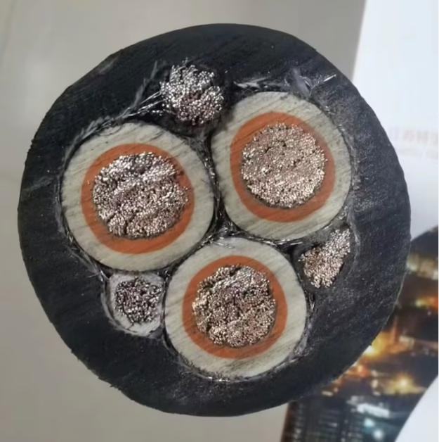
In the (N)TSCGEH3S construction, three EL filaments (the “H3” component) are positioned in the interstices between the main power cores during the cabling (stranding) process. The interstices — triangular spaces formed naturally when round conductors are laid up together — provide a geometrically stable location that protects the delicate EL elements from mechanical compression during reeling operations. The EL wires are laid parallel to or helically around the core assembly with a lay length chosen to balance optical uniformity with mechanical stress distribution.
在 (N)TSCGEH3S 结构中,三根 EL 发光丝(”H3″部分)在成缆(绞合)过程中被放置于主电力芯线之间的间隙中。这些间隙——圆形导体合拢时自然形成的三角空间——为脆弱的 EL 元件提供了几何稳定的保护位置。
For the direct connection variant, an additional pair of fine-gauge wires (typically 0.5 – 1.0 mm² flexible copper Class 5 per IEC 60228) is cabled into the assembly, routed from the drum-end termination through the entire cable length to the equipment-end connector. The inverter, sized to drive up to three parallel EL strands simultaneously, is housed in an IP65-rated enclosure at the drum junction. For the inductive coupling variant, no additional wires are present; the EL strands rely entirely on the electromagnetic field generated by the cable’s operational current flow. The spiral-wound angel-hair conductors of the EL wire are engineered with a pitch optimized to maximize flux linkage with the adjacent power cores at the cable’s rated current.
直连方案需额外加入一对细规格导线(通常 0.5–1.0 mm²),逆变器安装在卷筒端 IP65 防护接线盒中。感应耦合方案则无需额外导线,EL 线完全依靠电缆运行电流产生的电磁场获取能量。
| Component 组件 | Material 材料 | Specification 规格 |
|---|---|---|
| Power Cores 电力芯 | Tinned Cu, Class 5 per IEC 60228 | 3 × 25 – 3 × 150 mm² (typical range) |
| Earth Core 接地芯 | Tinned Cu, Class 5 | 50 % of power core cross-section |
| Core Insulation 芯线绝缘 | EPR (Ethylene Propylene Rubber) | Per DIN VDE 0207-20, rated 90 °C |
| EL Filaments (×3) 发光丝 | Phosphor-coated Cu + PVC sheath | Ø 2.3 – 3.2 mm per strand |
| EL Drive Conductors (direct only) | Tinned Cu, Class 5 | 2 × 0.75 mm² |
| Screen 屏蔽层 | Tinned Cu wire braid | ≥ 85 % optical coverage |
| Outer Sheath 外护套 | PCP (Polychloroprene) or TPU | Per DIN VDE 0207-5, oil & UV resistant |
| Voltage Rating 额定电压 | — | 0.6/1 kV (power cores); 300 V (EL circuit) |
| Min. Bending Radius 最小弯曲半径 | — | ≥ 7.5 × D (on drum); ≥ 4 × D (fixed) |
| Temperature Range 温度范围 | — | −25 °C to +90 °C (fixed); −25 °C to +80 °C (mobile) |
7. Application Scenarios & Selection Guide
7.1 When to Choose Direct Connection 何时选择直接连接
Direct connection is the preferred method when continuous, load-independent visibility of the cable is required — such as in port container crane installations, ship-to-shore (STS) gantry cranes, and open-pit mining draglines where the cable position must remain visible during all phases of operation, including idle periods and low-load positioning moves. In these environments, reliable EL illumination aids operators in monitoring cable routing to prevent snagging, tangling, or accidental damage during crane travel. Facilities operating under stringent safety standards such as FEM 1.001 (European Federation of Material Handling) or ASCE 7 loading criteria will typically mandate the direct-connection variant for its deterministic illumination performance.
当需要与负载无关的持续可见性时,应选择直连方式——例如港口集装箱起重机、岸桥(STS)门式起重机和露天矿山拖拽线设备。在这些场景中,可靠的 EL 照明有助于操作员监控电缆路径,防止缠绕和意外损坏。
7.2 When to Choose Inductive Coupling 何时选择感应耦合
Inductive coupling is well-suited for applications where the cable is always under significant load during operation — meaning the main power cores consistently carry substantial current whenever visibility is needed. Typical scenarios include bucket-wheel excavators, continuous mining equipment, tunnel boring machines (TBMs), and conveyor feeder systems where the drive motors draw steady-state current throughout the duty cycle. The inductive approach offers cost savings through reduced cable diameter, lower weight per meter, and elimination of the external inverter module, simplifying the drum termination and reducing potential points of failure.
感应耦合适用于电缆在运行期间始终承载大负荷的场景——例如斗轮挖掘机、连续采矿设备、隧道掘进机(TBM)和输送机给料系统。该方案通过减小电缆直径和重量、省去逆变器模块来降低成本。
| Application 应用 | Load Profile 负载特征 | Recommended Method 推荐方式 | Rationale 依据 |
|---|---|---|---|
| Container STS Crane 集装箱岸桥 | Variable (idle + full load) | Direct Connection | Visibility required during all phases |
| RTG / RMG Gantry Crane 轨道门吊 | Intermittent | Direct Connection | Cable routing critical in yard operations |
| Bucket-Wheel Excavator 斗轮挖掘机 | Continuous high load | Inductive Coupling | Steady current ensures stable illumination |
| TBM (Tunnel Boring) 隧道掘进机 | Continuous high load | Inductive Coupling | Reduced diameter aids in confined space |
| EOT / Overhead Crane 桥式起重机 | Variable | Direct Connection | Operator needs constant cable awareness |
| Conveyor Feeder 输送机给料 | Continuous moderate | Inductive Coupling | Cost-effective for long cable runs |
| Spreader / Lifting Magnet 吊具/电磁铁 | High during lift cycle | Direct Connection | Safety-critical visibility needed at rest |
8. Applicable Standards & Compliance
The design and manufacturing of (N)TSCGEH3S cables must comply with a body of international and national standards governing conductor construction, insulation materials, mechanical performance, fire behavior, and the special requirements for embedded luminescent elements. The table below summarizes the key standards framework applicable to this cable type.
(N)TSCGEH3S 电缆的设计和制造须符合一系列国际和国家标准,涵盖导体结构、绝缘材料、机械性能、阻燃性能及嵌入式发光元件的特殊要求。
| Standard 标准 | Scope 范围 | Relevance 关联性 |
|---|---|---|
| DIN VDE 0250 | Cables for power installations (Germany) | Primary standard for cable type designation and construction |
| DIN VDE 0207 | Insulating and sheathing compounds | Specifies EPR, PCP, TPU material requirements |
| DIN VDE 0292 | Type designation codes | Defines the letter-coding system for cable nomenclature |
| DIN VDE 0298-3 | Current-carrying capacity & bending radii | Minimum bending radius for drum reeling cables |
| IEC 60245 | Rubber-insulated cables rated up to 450/750 V | International harmonization for flexible rubber cables |
| IEC 60228 | Conductors of insulated cables | Class 5 (flexible) conductor construction |
| IEC 60332-1-2 | Flame retardance — single cable test | Fire behavior of outer sheath |
| EN 60811 | Test methods for insulation and sheath | Ageing, oil resistance, abrasion tests |
| VDE 0295 (Class 6) | Extra-flexible conductors | For EL drive conductor pairs (direct connection variant) |
9. Conclusion & Recommendation
Both powering methods for the EL elements in (N)TSCGEH3S cables are valid engineering solutions, each optimized for different operational realities. Direct galvanic connection delivers deterministic, load-independent illumination with high brightness and consistency — making it the preferred choice for safety-critical applications, variable-load machinery, and installations requiring regulatory certification of continuous cable visibility. Inductive coupling offers a more economical, mechanically elegant solution for applications characterized by continuous high-load operation where the parasitic electromagnetic field reliably provides sufficient excitation energy to the EL phosphor layer.
两种 EL 元件供电方式均为有效的工程方案。直接连接提供确定性的、不依赖负载的照明,适用于安全关键型应用和可变负载设备。感应耦合为持续高负荷运行工况提供了更经济、结构更简洁的解决方案。
When specifying (N)TSCGEH3S cables for a new installation, Anhui Feichun Special Cable Co., Ltd. recommends that engineering teams evaluate the duty cycle load profile, minimum bending radius requirements, applicable safety codes, and the criticality of zero-load visibility before selecting the EL powering method. Our technical team can provide customized cable cross-section calculations and EL performance simulations for both variants to ensure optimal integration with your specific crane or reeling system.
安徽飞纯特种电缆有限公司建议工程团队在选型时评估负载工况、最小弯曲半径、安全规范及空载可见性需求。我们的技术团队可为两种方案提供定制化截面计算和 EL 性能仿真。
For most port and crane installations with variable load cycles: choose direct connection. For continuous mining and tunneling equipment with sustained load: inductive coupling provides a cost-effective alternative without compromising operational safety.
对于大多数负载周期可变的港口和起重机安装:选择直接连接。对于持续负载的矿山和隧道掘进设备:感应耦合是一种不影响安全的高性价比替代方案。
References & Sources 参考文献
- Wikipedia contributors, “Electroluminescent wire,” Wikipedia, The Free Encyclopedia, 2025. en.wikipedia.org/wiki/Electroluminescent_wire
- SparkFun Electronics, “Getting Started with Electroluminescent (EL) Wire,” SparkFun Learn. learn.sparkfun.com
- Adafruit Industries, “Working with Electroluminescent Wire,” Adafruit Learning System. learn.adafruit.com/el-wire
- HowStuffWorks, “How Electroluminescent (EL) Wire Works.” science.howstuffworks.com
- Auckland UniServices Limited, “Power supply for an electroluminescent display,” Patent WO1998/050993A1. patents.google.com/patent/WO1998050993A1
- Conductix-Wampfler, “Inductive Power Transfer Solutions — Rail.” conductix.de
- Overhead Lifting, “Crane Electrification Options: Conductor Bars, Festoons, and Cable Reels,” ECMA / ANSI ECMA 35, 2023. overheadlifting.org
- Faber Kabel, “Type Designation Code for Cables,” DIN VDE 0292 Reference. faberkabel.de — Technical Data (PDF)
- Eland Cables, “FAQ: What do cable designations mean?” elandcables.com
- Eland Cables, “DIN VDE Standard Cable.” elandcables.com — VDE
- Feichun Special Cable, “Understanding Cable Standards: IEC vs. DIN VDE vs. BS EN.” cranecable.com.au
- Mazzella Companies, “Crane Electrification: Conductor Bars vs. Cable Festoon vs. Cable Reel,” 2023. mazzellacompanies.com
- Adafruit Industries, “Red Electroluminescent (EL) Wire — 2.5 meters,” Product #403 Datasheet. adafruit.com/product/403
- DIN VDE 0250: Cables, wires and flexible cords for power installations — German National Standard.
- IEC 60245: Rubber insulated cables — Rated voltages up to and including 450/750 V.
- IEC 60228: Conductors of insulated cables — International Electrotechnical Commission.


