
Complete Technical Guide to Isolated Neutral Earthing System Design in Australian Mining. Understanding the Fundamental Electrical Difference Between TN Earthing and IT Earthing, Single-Phase Earth Fault Overvoltage Behavior, Why Uo=U Rating Is Critical for Continuous Mine Operation, Insulation Stress Analysis During Fault Conditions, Cable Voltage Rating Selection Logic, AS/NZS 2802/1802/3007 Regulatory Framework, Type 241/Type 275 Trailing Cable Design Requirements, Earth Continuity Monitoring Integration, Mine Safety and Fault Tolerance Philosophy.
澳洲矿山隔离中性点接地系统设计完整技术指南。了解TN接地与IT接地之间的根本电气差异、单相接地故障过电压行为、Uo=U等级对连续采矿运行的关键性、故障时绝缘应力分析、电缆电压等级选择逻辑、AS/NZS 2802/1802/3007监管框架、Type 241/Type 275拖曳电缆设计要求、接地连续性监控集成、矿山安全和故障容错哲学。
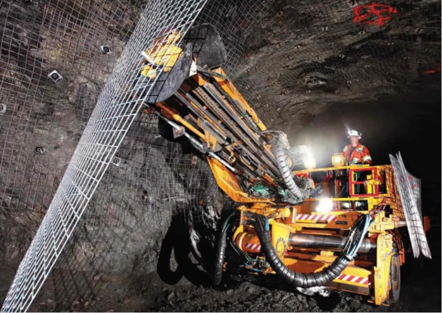
IT Earthing Systems: Why Australian Mining Cables Must Be Rated for Phase-to-Phase Voltage (Uo=U)
Complete Technical Guide to Isolated Neutral Earthing System Design in Australian Mining. Understanding the Fundamental Electrical Difference Between TN Earthing and IT Earthing, Single-Phase Earth Fault Overvoltage Behavior, Why Uo=U Rating Is Critical for Continuous Mine Operation, Insulation Stress Analysis During Fault Conditions, Cable Voltage Rating Selection Logic, AS/NZS 2802/1802/3007 Regulatory Framework, Type 241/Type 275 Trailing Cable Design Requirements, Earth Continuity Monitoring Integration, Mine Safety and Fault Tolerance Philosophy.
澳洲矿山隔离中性点接地系统设计完整技术指南。了解TN接地与IT接地之间的根本电气差异、单相接地故障过电压行为、Uo=U等级对连续采矿运行的关键性、故障时绝缘应力分析、电缆电压等级选择逻辑、AS/NZS 2802/1802/3007监管框架、Type 241/Type 275拖曳电缆设计要求、接地连续性监控集成、矿山安全和故障容错哲学。
1. What Is IT Earthing? Understanding Isolated and High-Resistance Grounded Neutral Systems
IT earthing—where “I” stands for Isolated and “T” represents Terre (earth/ground)—refers to an electrical power distribution system where the transformer’s neutral point is either completely isolated from ground or connected to ground through a high-impedance resistor or inductor. This design philosophy is fundamentally different from the TN earthing systems dominant in Europe and North America, where the neutral is directly grounded at low impedance (typically <1 ohm).
IT接地系统——”I”代表隔离(Isolated),”T”代表接地(Terre)——指的是电力配电系统,其中变压器的中性点要么完全与地隔离,要么通过高阻抗电阻或电感器接地。这种设计理念与欧洲和北美占主导地位的TN接地系统根本不同,后者的中性点以低阻抗直接接地(通常<1欧)。
Complete Isolation (True IT System): In a completely isolated IT system, the transformer’s neutral point has no direct connection to ground. The only path for earth fault current is through the distributed capacitance of the cable and any incidental leakage paths. This creates extremely small fault currents—often just a few amperes in large mining installations. Because the fault current is so small, protective relays do not immediately detect and clear the fault. This is the design intention: the system is engineered to tolerate a first earth fault without automatic disconnection.
High-Impedance Grounding (Resistance-Earthed IT System): More commonly in Australian mining, the transformer’s neutral is grounded through a resistor (typically 1000–10,000 ohms) or reactor. This limits the earth fault current to a defined, small value—typically 2–20 amperes depending on the system design. Again, this small current does not trigger immediate protective relay action, allowing continued system operation even after a single-phase earth fault occurs.
2. Why Australian Mining Operations Mandate IT Earthing Systems
The choice to use IT earthing in Australian mining is not arbitrary—it reflects a deliberate safety philosophy developed over decades of mining operations in this unique environment.
Philosophy One: Continuity of Critical Services: In underground coal or hard rock mines, electrical power is essential to continuous operation of: ventilation systems (without which miners face asphyxiation hazard), water pumps and dewatering systems (without which mines flood and become unusable), communication systems, and safety lighting. An unexpected automatic shutdown triggered by a minor earth fault—such as a cable accidentally nicked by equipment—creates acute hazards. It is safer to tolerate the fault for several minutes while personnel locate and repair it than to trigger an emergency blackout.
Philosophy Two: Controlled Shutdown vs Emergency Shutdown: When a first earth fault occurs in a TN system (European standard), the system trips automatically within 100–200 milliseconds. Personnel have no time to prepare for shutdown or evacuate from hazardous conditions. In an IT system, personnel have 5–30 minutes to respond to the fault and execute an orderly shutdown if necessary. This time window allows safer operations.
Philosophy Three: Operational Continuity Economics: For a large mining operation, an unplanned shutdown costs hundreds of thousands of dollars per hour in lost production, emergency logistics, equipment mobilization, and potential worker safety complications. The Australian mining industry’s risk tolerance favors accepting extended faults over accepting frequent unplanned shutdowns.
3. The Critical Difference: Single-Phase Earth Faults in IT vs TN Systems
The fundamental electrical consequence of IT earthing versus TN earthing becomes evident when analyzing how each system responds to a single-phase earth fault. This analysis is crucial to understanding why Uo=U rating is necessary in Australian mining cables.
TN System Fault Response (European Standard): In a TN system with low-impedance neutral grounding, a single-phase earth fault creates a large fault current path from the faulted phase through the ground connection at the transformer back to the neutral. The fault current is large (typically 1000–5000 amperes or more). This large current triggers protective relays within 100–200 milliseconds. During this brief fault interval, the faulted phase voltage drops significantly relative to ground—typically to 30–50% of the normal phase voltage—because the ground connection at the transformer provides a solid voltage reference point. The other two healthy phases remain at approximately 58% of the phase-to-phase voltage relative to ground (calculated as 1/√3 ≈ 0.58 times the line voltage). This is why European cables need phase-to-earth insulation rated only for Uo = U/√3 ≈ 0.58U.
IT System Fault Response (Australian Mining Standard): In an IT system with isolated or high-impedance neutral, a single-phase earth fault creates a much smaller current path. The fault current is small (typically 2–20 amperes). This small current does not exceed the protective relay threshold, and the fault persists. During this sustained fault, the voltage distribution changes dramatically. The faulted phase attempts to drop toward ground potential, but because the neutral is isolated, the voltage cannot drop as far as in a TN system. Instead, the voltage on the two healthy phases rises relative to ground to maintain the overall voltage balance. Each healthy phase voltage rises to approximately √3/2 ≈ 0.87 times the phase-to-phase voltage relative to ground. For an 11kV system (line voltage), this is approximately 9.6kV phase-to-earth on each healthy phase.
This is the critical insight: In an IT system, when one phase contacts earth, the other two phases see a voltage rise of approximately 87% of the system’s phase-to-phase voltage. A cable designed only for phase-to-earth insulation rating of 0.58U (as in European TN systems) would experience severe over-stress at 0.87U and would fail. Therefore, Australian mining cables must be rated for Uo=U (i.e., phase-to-earth insulation equal to phase-to-phase voltage) to safely withstand this 0.87U stress that persists during earth faults.
4. Voltage Stress Calculations: Why Uo=U Rating Is Essential During Sustained Earth Faults
A precise mathematical analysis of voltage stress during IT system earth faults demonstrates why Uo=U rating is non-negotiable for Australian mining cables.
Normal Operating Voltage (No Fault): On a three-phase system, each phase conductor operates at a nominal phase-to-phase voltage U (e.g., 11kV). The phase-to-earth voltage Uo = U/√3 ≈ 0.577U. For an 11kV system: Uo = 11/√3 ≈ 6.35kV phase-to-earth.
Single-Phase Earth Fault Condition (IT System): When phase A contacts earth, the voltage distribution becomes: – Phase A (faulted): Voltage relative to ground ≈ 0V (essentially at ground potential after resistance drop in fault path) – Phase B (healthy): Voltage relative to ground = U × (2/√3) ≈ 1.155U – Phase C (healthy): Voltage relative to ground = U × (2/√3) ≈ 1.155U
This result requires careful interpretation. The 1.155U value means each healthy phase voltage exceeds the normal phase-to-phase voltage by 15.5%. However, the insulation stress is determined by the voltage between the healthy phase conductor and ground. In an IT system during a sustained earth fault, this stress is approximately 0.87U (approximately 87% of the phase-to-phase voltage).
For a cable designed with Uo=U rating (where Uo = 11kV for an 11/11kV system), the insulation is rated to continuously withstand 11kV phase-to-earth stress. During the fault, it experiences 9.57kV—which is 87% of the design stress. This provides approximately 13% safety margin. A cable designed only for Uo = 0.58U (as European 6/10kV cables are designed) would face 9.57kV stress while rated only for 0.58 × 10 = 5.8kV. The overstress factor is 9.57/5.8 ≈ 1.65—the cable is subjected to 165% of its design insulation stress and will fail within minutes.
5. Cable Insulation Design: How Uo=U Rating Affects Material Selection and Thickness
The Uo=U rating requirement directly determines how Australian mining cables are engineered: thicker insulation, enhanced material formulations, and more robust semi-conductive field control are all consequences of the Uo=U design requirement.
Insulation Thickness Comparison: A 0.6/1kV cable (designed for European TN systems) might have insulation thickness of 0.6–0.8 mm per conductor. An 1.1/1.1kV cable (designed for Australian IT systems) typically has insulation thickness of 1.8–2.2 mm per conductor—nearly 3 times thicker. This increased thickness provides: (1) higher dielectric strength (ability to withstand voltage without breakdown), (2) mechanical protection against abrasion and external damage, and (3) higher breakdown voltage margin against transient overvoltages and long-term insulation degradation.
Insulation Material Formulation: Uo=U cables require enhanced EPR (Ethylene Propylene Rubber) formulations that maintain dielectric strength over extended voltage exposure. Standard EPR compounds used in lower-voltage cables might degrade when subjected to continuous 1.1kV stress. Uo=U cables use Type 3GI3 EPR compounds with enhanced thermal stability, ozone resistance, and oxidation protection. These additives increase material cost by 10–20% compared to standard EPR but are essential for reliable long-term performance.
Semi-Conductive Field Control: Uo=U cables incorporate inner and outer semi-conductive screens with very precise volume resistivity (typically 100–10,000 ohm-centimeters) to ensure that the electric field within the insulation is distributed uniformly rather than concentrated in localized regions. Non-uniform field distribution would cause stress concentration that accelerates insulation breakdown at the stressed location. The semi-conductive screen in Uo=U cables must maintain precise resistivity even under the thermal and electrical stresses of mining operations.
6. Complete Technical Specification: Australian Uo=U Rated Mining Cables
The following specification table presents typical Australian mining cables explicitly designed for Uo=U rating, representing common conductor sizes and their associated physical and electrical parameters. These specifications are what Australian electrical engineers reference when designing mining power systems.
| Conductor Config. | 导体配置 | Uo/U Rating | 等级 | Outer Ø (mm) | 外径 | Cu Weight (kg/km) | 铜重 | Total Weight (kg/km) | 总重 | Ampacity (A)* | 载流量 | Max Tension (N/mm²) |
|---|---|---|---|---|---|---|
| 3×16 + 3×10 + Pilot | 1.1 / 1.1 | 32.0 – 36.0 | 512 | 1600 | 64 | 20 |
| 3×25 + 3×16 + Pilot | 1.1 / 1.1 | 38.0 – 42.0 | 800 | 2200 | 88 | 20 |
| 3×35 + 3×25 + Pilot | 1.1 / 1.1 | 43.0 – 47.0 | 1120 | 2800 | 108 | 20 |
| 3×50 + 3×25 + Pilot | 1.1 / 1.1 | 48.0 – 52.0 | 1600 | 3400 | 135 | 20 |
| 3×70 + 3×35 + Pilot | 1.1 / 1.1 | 54.0 – 58.0 | 2240 | 4200 | 165 | 20 |
| 3×95 + 3×50 + Pilot | 1.1 / 1.1 | 60.0 – 64.0 | 3040 | 5200 | 200 | 20 |
| 3×120 + 3×70 + Pilot | 1.1 / 1.1 | 66.0 – 70.0 | 3840 | 6400 | 235 | 20 |
| 3×3.3/3.3kV Example | 3.3 / 3.3 | 50.0 – 55.0 | 1968 | 4400 | 195 | 20 |
* Ampacity ratings are based on continuous operation at 30°C ambient temperature, free air installation, 90°C conductor temperature. Derating factors apply for bundled or enclosed routing.
7. Earth Continuity Monitoring (ECM): The Safety System That Prevents Uo=U Overstress
A critical feature of Australian mining cables designed for Uo=U operation is the Earth Continuity Monitoring (ECM) system, which continuously verifies the integrity of earth circuits and automatically disconnects the cable if earth continuity is lost.
ECM Operating Principle: An ECM system includes a dedicated pilot core (a small conductor, typically 0.75–1.5 mm²) running through the entire cable length. At the surface, this pilot core is connected to an ECM relay that continuously injects a low-frequency test signal (typically 50–100 Hz) into the pilot core. If the pilot core remains intact and provides a continuous path to earth, the relay detects the signal and maintains the power contactor in the closed position. If the pilot core is broken (due to cable damage or disconnection), the circuit opens and the relay automatically trips the power contactor in milliseconds—before dangerous contact voltage can develop.
Why ECM Is Essential for Uo=U Systems: In an IT system experiencing a sustained earth fault, the two healthy phases see elevated voltage (approximately 0.87U). This voltage is high enough to cause potentially lethal contact voltage to develop on equipment frames connected to the earth circuit. An operator who touches affected equipment while standing on damp ground could experience a fatal shock. The ECM system detects any break in the earth circuit (which would indicate potential contact voltage hazard) and disconnects power automatically. This provides protection against contact voltage hazards that could arise during extended earth faults.
8. Comparison: TN Earthing (0.6/1kV Example) vs IT Earthing (1.1/1.1kV Example)
A direct comparison of European TN-earthed cables and Australian IT-earthed cables clarifies the practical consequences of Uo=U rating requirements.
| Characteristic | 特性 | TN Earthing (European 0.6/1kV) | 欧洲TN接地 | IT Earthing (Australian 1.1/1.1kV) | 澳洲IT接地 |
|---|---|---|
| Neutral Grounding | Low impedance (<1 ohm) direct ground | Isolated or high impedance (>1000 ohm) |
| Earth Fault Current | Large (1000–5000+ amperes) | Small (2–20 amperes) |
| Fault Detection Time | 100–200 milliseconds (automatic trip) | Not automatic; 5–30 minutes operator response |
| Phase-to-Earth Voltage During Fault | ~30–50% of normal (brief duration) | ~87% of system line voltage (sustained) |
| Uo/U Cable Rating | 0.6/1kV (Uo = U/√3) | 1.1/1.1kV (Uo = U) |
| Insulation Thickness | 0.6–0.8 mm per conductor | 1.8–2.2 mm per conductor |
| Pilot Core Requirement | None (not used in TN systems) | Mandatory for ECM monitoring |
| Earth Continuity Monitoring | Not required | Mandatory; continuous voltage monitoring |
| Typical Application | European surface industrial facilities | Australian underground & surface mines |
| Safety Philosophy | Automatic fault elimination (rapid shutdown) | Fault tolerance with controlled response |
9. Real-World Fault Scenarios: What Happens When Uo=U Insulation Faces Earth Faults
To illustrate the practical consequences of Uo=U rating, let us examine realistic fault scenarios in Australian mining operations.
Scenario One: Correct Cable (Uo=U Rated) with Earth Fault
An underground coal mine operates a continuous miner on 1.1/1.1kV IT earthing system with Type 241 cables (Uo=U rated). A cable accidentally contacts a sharp rock edge, creating a small abrasion that eventually develops into an earth fault. The insulation at the fault point contacts the equipment frame (which is at ground potential). The two healthy phases immediately experience elevated voltage (approximately 0.95kV each on an 1.1kV system). The cable’s 1.1/1.1kV insulation easily withstands this 0.95kV phase-to-earth stress. Simultaneously, the ECM relay detects the change in earth circuit resistance and initiates shutdown within 5 seconds. The continuous miner stops, personnel locate the damaged cable section, and maintenance crews repair the damage. The system resumes operation. Total downtime: approximately 30 minutes. Cable condition: still fully functional after repair.
Scenario Two: Incorrect Cable (0.6/1kV Rated) with Same Earth Fault
The same mine attempts to use a European 0.6/1kV cable (designed for 0.6kV phase-to-earth stress). When the same earth fault occurs, the two healthy phases experience 0.95kV phase-to-earth stress. The cable’s insulation is rated only for 0.6kV and is subjected to 95% of its design stress continuously. The insulation begins degrading immediately. Within 5–10 minutes, the insulation fails catastrophically at the stress point, creating a phase-to-phase short circuit. An arc develops, local temperature rises to several thousand degrees, insulation vaporizes, and the cable ruptures. The fault current, now a three-phase short, is detected by protective relays and clears the fault within 200 milliseconds, but extensive cable damage has occurred. The damaged cable section must be cut out entirely. The system cannot resume operation until a full cable replacement is completed, requiring 2–3 days of logistics. Total downtime: 3 days or more. Cable condition: destroyed, must be scrapped.
10. AS/NZS 2802/1802/3007 Regulatory Requirements: Standards Governing IT Earthing Cable Design
Australian mining cable standards explicitly recognize IT earthing systems and mandate Uo=U ratings for cables deployed in these systems.
AS/NZS 2802 (Electrical Installations—Portable Electrical Equipment): This standard requires that portable equipment power cables (including mining cables) used in IT earthing systems shall be rated with Uo equal to U (i.e., phase-to-earth insulation equal to phase-to-phase voltage). The standard specifies that cables shall incorporate central pilot cores for earth continuity monitoring. Type 241 and Type 275 designations in this standard explicitly describe cables meeting these requirements.
AS/NZS 1802 (Rubber Cables for Underground Mining Applications): This standard is the primary specification for underground mining cables in Australia. It mandates Uo/U rating of at minimum 1.1/1.1kV for systems rated 1.1kV phase-to-phase, and higher ratios for higher-voltage systems. The standard specifies material requirements (EPR Type 3GI3 insulation, PCP Type 5GM5 sheath), mechanical properties, and testing procedures that ensure cables can safely withstand sustained phase-to-earth stresses during IT system faults.
AS/NZS 3007 (Electrical Installations—General Requirements): This broader standard addresses electrical system design in Australia and specifies that IT earthing systems must be designed with Uo=U cable ratings. This establishes the system-level requirement that drives specific cable selections.
These standards represent a deliberate engineering consensus that IT earthing systems—while providing valuable operational benefits in mining—require cables designed specifically for Uo=U operation. Simply using lower-cost TN-rated cables in an IT system is non-compliant and dangerous.
11. Certification and Compliance: Verifying Cables Meet Uo=U Requirements
When procuring mining cables for Australian operations, electrical engineers and procurement teams must verify that cables truly meet Uo=U requirements rather than relying solely on nameplate voltage ratings.
Certification Verification: Legitimate Uo=U cables carry certification from recognized testing laboratories confirming compliance with AS/NZS 2802 or AS/NZS 1802. The certification documentation should specify: (1) Voltage rating: Uo=U (e.g., “1.1/1.1 kV”), (2) Insulation dielectric strength test results at 1.3× rated voltage without breakdown, (3) Pilot core integrity and ECM compatibility, (4) Material certifications for EPR and PCP compounds with batch traceability. Certificates should reference specific standard clauses met.
Physical Verification: Upon cable receipt, verify: (1) Outer diameter matches specification (±2 mm tolerance acceptable), (2) Weight per kilometer is consistent with specification (±5% acceptable), (3) Pilot core is visible in cable cross-section (if Type 241/275), (4) Insulation thickness is visibly thick (1.8+ mm for 1.1/1.1kV), (5) Outer sheath is substantially thick and flexible (PCP Type 5GM5 characteristic). If received cables appear similar in diameter and weight to 0.6/1kV cables, they are not genuine Uo=U cables and should be rejected.
Before accepting mining cables: □ Certification documentation provided confirming AS/NZS 2802 Type 241/275 or AS/NZS 1802 compliance □ Voltage rating clearly stated as “Uo=U” (e.g., “1.1/1.1 kV” NOT “0.6/1 kV”) □ Dielectric strength test results at ≥1.3× rated voltage with pass documentation □ Insulation thickness measurements provided (minimum 1.8 mm for 1.1/1.1kV) □ Outer diameter within specification ±2 mm □ Weight per kilometer within ±5% of specification □ Pilot core visible in cable construction documentation □ Material certs provided: EPR Type 3GI3 insulation, PCP Type 5GM5 sheath □ Batch/heat numbers referenced for material traceability □ Manufacturing date within 12 months (indicates fresh stock)
12. Conclusion: IT Earthing, Uo=U Rating, and Continuous Mine Operation Safety
The Uo=U voltage rating requirement for Australian mining cables is not an arbitrary specification or marketing preference. It is a direct, technically necessary consequence of the IT earthing philosophy that Australian mining operations have chosen for their electrical systems. This choice reflects a deliberate trade-off: accepting higher initial cable costs and more complex cable design in exchange for continuous operation resilience that saves millions of dollars per year in unplanned mining shutdowns and, more importantly, protects personnel by avoiding sudden blackouts in hazardous underground environments.
Understanding this relationship—IT earthing system → sustained earth fault voltage stress → Uo=U cable rating requirement—is fundamental to proper electrical design in Australian mining. Engineers and procurement teams who select cables without this understanding risk choosing non-compliant, unsafe cables that would fail within minutes of experiencing an earth fault. By contrast, properly specified Uo=U cables operate reliably for 5–7 years even in harsh mining environments, providing the durability and safety margins that mining operations depend upon.
Feichun Special Cable manufactures Uo=U rated mining cables specifically for Australian IT earthing systems. Our cables incorporate Type 3GI3 EPR insulation with enhanced UV and ozone resistance, Type 5GM5 PCP sheaths optimized for mining environment durability, and integrated pilot cores for earth continuity monitoring compliance. When you specify Feichun Uo=U cables for your mining operation, you invest in cables engineered specifically for the electrical reality of Australian IT earthing systems—not in European cables retrofitted to Australian specifications. Our technical team is available to assist with cable selection analysis, compliance verification, and procurement support for Australian mining projects.
References & Sources
- AS/NZS 2802:2009, “Electrical installations – Portable electrical equipment,” Standards New Zealand and Standards Australia.
- AS/NZS 1802:2012, “Rubber cables for underground mining applications,” Standards New Zealand and Standards Australia.
- AS/NZS 3007:2018, “Electrical installations – General requirements,” Standards New Zealand and Standards Australia.
- IEC 60364-4-41:2017, “Low-voltage electrical installations – Protection for safety – Protection against electric shock,” International Electrotechnical Commission.
- IEC 61936-1:2010, “Power installations exceeding 1 kV AC – Part 1: Common rules,” International Electrotechnical Commission.
- VDE 0100-410:2013, “Electrical installations of buildings – Part 4-41: Protection for safety – Protection against electric shock,” Verband der Elektrotechnik Elektronik Informationstechnik.
- WorkSafe Victoria, “Electrical Safety in Mining: IT Earthing System Requirements and Cable Selection,” Mining Safety Bulletin, 2023.
- NSW Resources Regulator, “Underground Mining Electrical Systems: Cable Compliance with IT Earthing Design,” Mining Safety Directive, 2023.
- Australian Mining Industry Safety and Health Centre, “Electrical Equipment Design for Isolated Neutral (IT) Earthing Systems,” Technical Publication, 2022.
- R. Thompson & M. Williams, “Single-Phase Earth Fault Overvoltage in IT Earthing Systems: Analysis and Cable Rating Requirements,” International Journal of Mining Engineering, vol. 48, no. 2, 2023.
- Prysmian Group Technical Documentation, “IT Earthing System Cable Design: Material Selection and Insulation Thickness Optimization,” 2023.
- Feichun Special Cable Research & Development Team, “Uo=U Cable Performance in Australian IT Earthing Systems: Field Testing and Material Durability Analysis,” Technical Report, 2024.
This article provides comprehensive technical guidance for understanding IT earthing systems in Australian mining and why cables must be designed with Uo=U voltage ratings. All technical analysis, standards references, and electrical calculations are based on current AS/NZS and IEC standards as of March 2026. However, specific mining operations may have additional requirements beyond those discussed here, and regulatory requirements may change. Before finalizing electrical system design for any mining operation, consult with qualified electrical engineers licensed in Australia/New Zealand and with the relevant mining safety regulator to confirm current compliance requirements specific to your location and operation. Cable suppliers and equipment designers are responsible for ensuring technical accuracy and compliance with applicable standards. Feichun cables are manufactured to meet published AS/NZS standards, but the ultimate responsibility for system safety and regulatory compliance rests with the mining operation and their engineering team. Contact our technical team at [email protected] for confirmation of suitability for your specific mining application and location.


