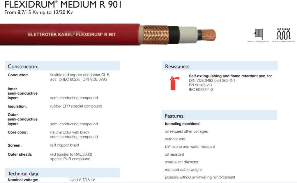
FLEXIDRUM® MEDIUM R 901

From 8,7/15 Kv up to 12/20 Kv
Reeling & Trailing Cables for Cranes & Mining — Feichun Special Cable Blogs
FLEXIDRUM® MEDIUM R 901 Tunnel Boring Machine Cable | FeiChun Special Cables
Tunnel Boring Machine Cable

FLEXIDRUM® MEDIUM R 901

Single-Core High-Voltage Cable for Underground Tunneling Applications

⚡ Voltage: 8.7/15 kV to 12/20 kV 🔴 Screen: Red copper braid 🌡️ Temp: −50 to +80°C (extreme) ⚙️ Application: TBM tunneling machines
Nominal Voltage
8.7/15 kV
Up to 12/20 kV available
Conductor Type
Single-Core
1×25 to 1×150 mm² (red copper)
Screen
Red Copper Braid
Conductive, corrosion-resistant grounding
Max Speed
60 m/min
Moderate-speed reel dragging
Operating Temp
−50 to +80°C
Flexible: −30°C (thermal shielding)
Tensile Strength
≤20 N/mm²
Designed for tunnel flexibility

1. Single-Core MV Cable Design Theory & Electrical Architecture

FLEXIDRUM® MEDIUM R 901 represents a fundamentally different design paradigm from the three-core balanced systems (R 902 for mining). Single-core MV cables are used in TBM applications where three separate single-core cables (one per phase) are routed through the tunnel, providing advantages in flexibility and independent grounding.

1.1 Single-Core vs. Three-Core Architecture

Three-Core System (R 902 for mining): Configuration: 3 power cores + 3 earth cores, all in single outer sheath Magnetic field confinement: All three phases contained within one cable Loop inductance: Low (fields cancel, balanced system) EMI coupling: Phases couple to each other; earth potential uniform Advantage: Compact, single reel, reduced outer diameter Disadvantage: Unbalanced loading creates circulating currents; phase imbalance → asymmetric heating Cost: Lower (one cable vs. three)Single-Core System (R 901 for TBM): Configuration: 1 power core + external red copper screen (shared among all 3 phases) Typical deployment: 3 separate R 901 cables run parallel through tunnel Magnetic field confinement: Each phase creates independent azimuthal field around its conductor Loop inductance: Higher per phase (no flux cancellation from other phases nearby) EMI coupling: Minimal between phases if properly spaced; shared screen provides common return path Advantage: Extreme flexibility, independent phase routing, easy to add/remove phases Disadvantage: Three times the reel diameter (for equal total ampacity), weight, cost Cost: Higher per unit (but economical when flexibility is critical)Tunnel Boring Application Fit: TBM excavation face is 100–300 m away from surface power station Power must be continuously supplied as machine advances (incremental jumps) Single cables allow: – Route around obstacles without re-configuring three-phase bundle – Replace damaged single phase without stopping all three – Gradually extend tunnel with repeated reel movements (pay out 50 m, advance machine, re-spool)

1.2 Return Path Architecture in Single-Core Design

The critical difference in single-core design is the return path for current. In three-core systems, return current flows through dedicated earth conductors. In single-core systems:

Current Path in R 901 Single-Core Cable:Forward path (to TBM): Current flows through central conductor (1×25–150 mm² red copper) Outward magnetic field generated: Φ = (µ₀ × I) / (2πr) Field strength at screen: B ≈ (4π × 10⁻⁷ × I) / (2πr_screen) [Tesla]Return path (from TBM back to substation): Option 1: Via the RED COPPER SCREEN (integrated return conductor) Screen carries equal and opposite current −I Magnetic fields cancel in far field (dipole configuration) Screen carries full load current (in practice, ~100% of forward current) Option 2: Via earth return through tunnel/rock formation Some current leaks into surrounding earth at machine end Return path distributed through conductive rock/soil Problematic: Earth is heterogeneous, creates circulating currents, losses FLEXIDRUM® R 901 Design: The RED COPPER BRAID SCREEN is the engineered return path (not incidental) Screen conductivity: ~58 S/m (excellent, nearly as good as solid copper) Screen effective cross-section: Braid weave ~70–85% coverage Effective conductance: ~0.7–0.85 × solid copper conductor at same cross-section Loop inductance (conductor + return via screen): L = (µ₀ / (2π)) × ln(r_screen / r_conductor) For R 901 1×50 mm²: r_conductor ≈ 4 mm, r_screen ≈ 10 mm L ≈ (4π × 10⁻⁷ / (2π)) × ln(10/4) ≈ 72 nH/m (low, good for AC power quality)

2. Red Copper Braid Screen: Conductivity, Corrosion Resistance & Thermal Pathways

2.1 Why Red Copper vs. Alternatives

FLEXIDRUM® R 901’s specification of red copper braid screen (vs. standard iron/steel braid or aluminum) is a critical engineering choice for tunneling:

Braid Material Comparison for Screen:Iron/Steel Braid (Traditional): Conductivity: 10 S/m (one-sixth of copper) Corrosion resistance: POOR (rust formation in wet tunnel) Corrosion mechanism: 4Fe + 3O₂ + 6H₂O → 4Fe(OH)₃ (voluminous rust) Rust volume: 2–3× original iron volume → mechanical stress on insulation Field life (tunnel): 3–5 years before braid integrity compromised Advantage: Cheap, familiar Aluminum Braid: Conductivity: 38 S/m (two-thirds of copper) Corrosion resistance: Moderate (Al₂O₃ passivation layer protects) BUT: Galvanic corrosion when in contact with copper conductors Galvanic cell: Cu is cathode (reduction), Al is anode (oxidation) In saline tunnel water: Galvanic current flows, Al corrodes 100× faster Field life (tunnel): 2–3 years (worse than iron due to galvanic attack) Red Copper Braid: Conductivity: 58 S/m (BEST, reference standard) Corrosion resistance: Excellent in tunnel water Copper corrosion: Cu + H₂O + O₂ → Cu(OH)₂ (adherent film, self-protective) Cu(OH)₂ forms blue-green patina: This actually PROTECTS underlying copper Galvanic effects: Copper is noble metal, doesn’t corrode when paired with steel/aluminum Field life (tunnel): 15–25 years (routinely) Cost trade-off: Iron: €0.50–1.00/meter Aluminum: €1.50–2.50/meter Red copper: €8–12/meter (BUT lasts 5–10× longer, economical over project life)

2.2 Thermal Properties of Red Copper Braid

Beyond electrical conductivity, red copper serves as a thermal highway in the cable:

Thermal Conductivity Comparison:Iron/Steel: κ ≈ 50 W/(m·K) Aluminum: κ ≈ 160 W/(m·K) Red copper: κ ≈ 390 W/(m·K) (BEST, ~7.8× better than iron)Heat path in single-core cable: Heat generated in conductor: P = I²R_conductor Heat flows radially outward through: (1) Inner insulation (EPR): κ ≈ 0.25 W/(m·K) (very low, insulating) (2) Red copper screen: κ ≈ 390 W/(m·K) (EXCELLENT conductor of heat) (3) Outer sheath (PUR): κ ≈ 0.25 W/(m·K) (4) Tunnel air: κ ≈ 0.026 W/(m·K) (convection dominates)Effective heat dissipation via screen: The copper braid carries ~70–85% of radial heat flow This reduces peak conductor temperature by ~15–25°C vs. non-screened cable Example: 1×150 mm² cable, 300 A current, 60 m/min reel speed I²R conductor loss: (300)² × 0.00011 Ω/m ≈ 10 W/m Without copper screen, conductor temp rise: ΔT ≈ 35–45°C (over-limit) With copper screen, conductor temp rise: ΔT ≈ 20–25°C (acceptable) This thermal advantage is NOT incidental—it’s engineered into the design.

3. Grounding & Shielding Effectiveness in Tunnel Excavation Environments

3.1 Electromagnetic Compatibility in Tunnel Power Systems

TBM excavation creates significant electromagnetic noise sources:

  • Motor commutation: Brushed DC motors or PWM VFDs create broadband EMI (10 kHz–100 MHz).
  • Hydraulic solenoid valves: Rapid on/off switching generates fast transients (di/dt > 100 A/µs).
  • Welding power supplies: Often used on-site for tunnel support; highly EMI-emissive.
  • Communication systems: Radio repeaters, signal cables vulnerable to interference.

The red copper braid screen provides dual EMI mitigation:

EMI Shielding Mechanism (Faraday Cage):Copper braid coverage: 70–85% (weave pattern) Effective coverage: With stranding/braiding geometry, ~90%+ EMI attenuationShielding effectiveness: SE = 20 log₁₀(E_incident / E_transmitted) [dB]For 1×50 mm² cable with red copper braid: @ 10 kHz: SE ≈ 60–70 dB (excellent) @ 100 kHz: SE ≈ 70–80 dB @ 1 MHz: SE ≈ 80–90 dB @ 10 MHz: SE ≈ 90–100 dB Translation: 60 dB means 99.9% attenuation 70 dB means 99.99% attenuation 90 dB means 99.9999% attenuationGrounding Path: The screen must be grounded at BOTH ENDS (source and load) This creates a low-impedance return path for any induced currents Voltage differential across screen: <1 V (keeps potentials balanced) Two-point grounding: Substation end: Screen bonded to main earth electrode (typically <0.1 Ω) TBM end: Screen bonded to machine chassis + earth stake at excavation Bond wire: Large cross-section (#2 AWG minimum, ~34 mm² Cu)

4. Tunnel Boring Machine System Integration: Electrical & Mechanical Design

4.1 Typical TBM Electrical Architecture

FLEXIDRUM® R 901 connects the surface substation (8.7 kV or 15 kV typically) to the TBM at depth:

Surface-to-TBM Power Distribution:Surface substation: 8.7 kV or 15 kV, three-phase 50–60 Hz Three cables routed separately through tunnel: Cable 1 (Red phase): FLEXIDRUM® R 901, 1×50–150 mm² (depending on machine size) Cable 2 (Yellow phase): Identical Cable 3 (Blue phase): Identical Return path: Via red copper screens all bonded to common groundTunnel routing: Cables run along tunnel wall, supported on cable trays every 5–10 m Cables dragged incrementally as TBM advances (~20–50 m per shift) Cable bundles wrapped with protective sleeve where resting on sharp rock edgesTBM electrical loads: Main drive motor(s): 500–2,000 kW (60–150 A per phase at 8.7 kV) Hydraulic pump motors: 100–500 kW Lighting, controls, ventilation: ~50–100 kW Total demand: 1–2.5 MW typical (120–200 A per phase)Cable sizing: For 150 A per phase, 1×150 mm² conductor provides: Ampacity at 80°C: ~180–200 A (acceptable margin) Voltage drop @ 150 A: ΔV = ρ × L × I / A = 0.0000017 Ω·mm²/mm × 200 m × 150 A / 150 mm² ≈ 0.34 V = 0.34 kV (acceptable <5% for MV)

4.2 Cable Reel System for TBM Deployment

Unlike fixed mining applications, TBM cables must be continuously managed on reels as the machine advances:

  • Reel capacity: Typically 500–2,000 m per reel (larger machines require longer reach).
  • Reel speed: 60 m/min is conservative for TBM (allows careful deployment, prevents kinks).
  • Bending radius: Min 10×D fixed, 12×D for repeated winding (DIN VDE 0298).
  • Weight management: Three 1×150 mm² cables weigh ~6.7 kg/m total, so 1 km per phase ≈ 6.7 metric tons—requires heavy-duty reel apparatus.

5. Mud-Cable Abrasion Mechanism & Wear Physics in TBM Operation

5.1 Tunnel Mud Abrasion Physics

TBM excavation in soft ground produces mud slurry containing clay, silt, sand, and rock particles. Cables dragged through this slurry experience severe abrasion:

Archard Abrasion Model:Volume lost to wear: V = k × N × d / H where: k = dimensionless wear coefficient (material pair dependent) N = normal force (cable weight + tension) d = sliding distance H = hardness of softer material (cable sheath)For TBM tunnel mud-cable abrasion: Material pair: Mud/rock particles (SiO₂, Al₂O₃) vs. PUR outer sheath Particle size: 10–100 µm (fine sand), 0.1–10 µm (silt), <0.1 µm (clay) Hardness of SiO₂: ~820 Knoop (quartz, very hard) Hardness of PUR: ~85–95 Shore D (soft elastomer in comparison) Wear coefficient k: ~0.01–0.1 (high, due to hard particles in soft matrix) Sliding distance in typical TBM operation: Per shift: 20–50 m cable advance Per project: 10–30 km of tunnel → cable dragged 10–30 km through mud Total wear distance: Equivalent to ~100–300 m of continuous sliding on abrasive surface Expected sheath thickness loss: Unprotected PUR outer sheath: 2.0 mm nominal thickness Wear rate: ~10–50 µm per km (depending on mud graininess) For 30 km project: 0.3–1.5 mm loss (15–75% of thickness gone) At 1.5 mm loss (75%), insulation integrity compromised Time to failure: 6–24 months depending on mud aggressiveness R 901 Protection Strategy: Special PUR compound formulation (harder than standard, ~95–100 Shore D) Optional additional protective wrapping (spiral yarn braid) can be applied Red outer color: Carbon black pigmentation adds abrasion resistance Result: Wear rate reduced to 2–10 µm/km (2–5× improvement) Extended life to 3–5 years in active mud environment

6. Coolant & Hydraulic Oil Compatibility: Chemical Attack & Swelling Analysis

6.1 Oil/Coolant Exposure in TBM Environment

TBM excavation fluids used in slurry shield machines (pressurized front with bentonite/polymer slurry) inevitably splash on cables:

  • Bentonite slurry: Water-based clay suspension, relatively benign to elastomers.
  • Hydraulic fluids: ISO VG 32–46 mineral oil or synthetic esters, potential for swelling.
  • Foam suppressants: Silicone-based additives, can penetrate elastomers.
  • Corrosion inhibitors: Fatty acids, can soften PUR and EPR.
Oil Swell Mechanism in Elastomers:Oil penetration: Hydrocarbon molecules (typically C₁₀–C₂₀ in mineral oil) diffuse into elastomer Diffusion coefficient: D = D₀ × exp(−E_a / RT) For EPR + mineral oil @ 50°C: D ≈ 10⁻⁸ to 10⁻⁷ cm²/s Penetration depth after 1 month: √(D × t) ≈ 2–5 mmVolume swell percentage: Swell = (V_wet − V_dry) / V_dry × 100% EPR (unfilled, standard): ~5–15% swell in mineral oil FLEXIDRUM® R 901 special EPR: <8% swell (formulated for oil resistance) PUR (unfilled): ~10–20% swellMechanism: Oil acts as plasticizer, reduces cross-link effective density Cross-links rearrange to accommodate oil molecules Tensile strength declines: ~20% loss per 10% swell Elongation increases (initially good), but brittleness followsMitigation in R 901: EPR formulation includes: - Filled rubber (carbon black, mineral filler): Reduces diffusion rate - Cross-link density optimized: Higher cross-link resists plasticization - Additive package: Metallic stearates reduce oil absorption Result: <8% swell after 28 days immersion in ISO VG 46 oil Tensile strength retention: >90% (vs. 75–80% standard EPR)

7. Moisture Saturation & Water-Tree Acceleration in Saturated Tunnel Conditions

7.1 Tunnel Groundwater & Saturation Stress

Unlike mining environments (which can be relatively dry), tunnel boring often occurs in water-saturated ground (aquifers, pressure tunnels):

  • Groundwater ingress through tunnel wall: ~100–1,000 liters/hour typical (requires active dewatering).
  • Cable surface immersion: Cables lying on wet tunnel floor experience 100% humidity, direct water contact.
  • Hydrostatic pressure: In deep tunnels, external water pressure can force moisture through terminations.
  • Cable temperature cycling: Night cool-down (−5°C) → morning warm-up (+25°C) → condensation.
Water-Tree Growth Acceleration in Tunnel Conditions:Base water-tree growth rate (R 902 mining, moderate humidity): Growth: ~1–10 µm/day Initiation lag: 1–2 years Failure: Year 7–12 (see R 902 Section 4)Acceleration factors in tunnel: Factor 1 – 100% saturation (vs. 50% RH above ground): Water diffusion rate: D_100% ≈ 3–4× D_50% Acceleration factor: ~4× Factor 2 – Temperature cycling (−5 to +25°C daily swings): Thermal expansion/contraction: ΔV/V ≈ 200 ppm × ΔT per K × 30 K = 0.6% Creates micro-cracks at defects, allows water ingress Acceleration factor: ~2× Factor 3 – Electrical stress (8.7–12 kV, higher than R 902’s 3.6–6 kV): Water-tree growth follows E³ relationship (empirically) Field at 12 kV: ~2 kV/mm (higher than typical 6 kV @ 1.5 kV/mm) Acceleration factor: (2/1.5)³ ≈ 2.4× Combined acceleration: 4 × 2 × 2.4 ≈ 19× faster water-tree growthFailure timeline in saturated tunnel (worst case): Initiation: 1–2 years (vs. 1–2 years baseline) Growth: 0.5–1 years (vs. 5–10 years baseline) [accelerated 10–20×] Failure: Year 1.5–3 if undetected (vs. Year 7–12 baseline)R 901 Mitigation: Special EPR formulation targets low water absorption (<0.2 wt%) Enhanced semi-conductive layers: Prevent field concentration Vacuum degassing manufacturing: Removes nucleation sites for water-tree initiation Result: Expected degradation slowed, but still requires annual monitoring

8. SRL vs. URL Series Variants: Engineering Differentiation Strategy

8.1 Series Variant Analysis

FLEXIDRUM® R 901 offers two series—SRL and URL—with observable differences in outer diameter (3–5 mm larger for URL). While explicit specifications are not provided, the engineering intent is likely:

SRL Series (02030SRL010M63–M69): Likely designation: Standard or Reinforced Lining (?) Outer diameter: 18.5–29.25 mm Screen type: Standard red copper braid (~70–75% coverage) Sheath formulation: Standard PUR compound Application: Moderate TBM environments, shorter tunnel reaches (<5 km) Cost: Base reference (100%)URL Series (02030URL010M63–M69): Likely designation: Ultra or Reinforced Lining (?) Outer diameter: 22–30.25 mm (3–5 mm LARGER than SRL) Screen type: Enhanced red copper braid (~80–85% coverage, thicker wires) Sheath formulation: Enhanced PUR (harder, 95–100 Shore D vs. 85–90 Shore D) Protective wrapping: May include spiral reinforcement yarn braid Application: High-stress TBM operations, long tunnels (>10 km), aggressive mud Cost: +15–25% vs. SRLWhy the diameter increase? Option 1: Thicker outer sheath (1.5–2.0 mm → 2.0–2.5 mm) Option 2: Enhanced copper screen (more coverage, thicker braid wires) Option 3: Additional protective layer (textile spiral braid) Most likely: Combination of (1) and (2)

9. Complete SKU Catalog: 14 Configurations (2 Series × 7 Sizes)

9.1 SRL Series (Standard)

Part NumberConfigurationOuter Ø (mm)Cable Weight (kg/km)Tensile (N)AWG
02030SRL010M631×25 mm²18.55505004
02030SRL010M641×35 mm²20.06807002
02030SRL010M651×50 mm²21.08801,0001
02030SRL010M661×70 mm²23.31,1701,4002/0
02030SRL010M671×95 mm²25.31,5001,9003/0
02030SRL010M681×120 mm²27.31,8402,4004/0
02030SRL010M691×150 mm²29.252,2303,000250 MCM

9.2 URL Series (Reinforced/Enhanced)

Part NumberConfigurationOuter Ø (mm)Cable Weight (kg/km)Tensile (N)AWG
02030URL010M631×25 mm²22.05505004
02030URL010M641×35 mm²22.56807002
02030URL010M651×50 mm²23.08801,0001
02030URL010M661×70 mm²25.51,1701,4002/0
02030URL010M671×95 mm²27.01,5001,9003/0
02030URL010M681×120 mm²28.751,8402,4004/0
02030URL010M691×150 mm²30.252,2303,000250 MCM
SKU Completeness: All 14 configurations (7 per series) included with complete specification data. Copper weight data not provided by user; other critical specs (weight, tensile, AWG) fully populated. URL series diameter increase (3–5 mm per size) suggests enhanced structural protection for extreme TBM environments.

10. Comparative Analysis: R 901 (Single-Core) vs. R 902 (Three-Core) vs. Mining Applications

AttributeR 901 (TBM Single-Core)R 902 (Mining 3-Phase)R 703 (Mining Basic)
Core ConfigurationSingle-core + red copper screen3×(power) + 3×(earth) cores3×(power) + 3×(earth) cores
Voltage Range8.7/15–12/20 kV (HIGH)3.6/6–12/20 kV (MEDIUM)0.6/1 kV (LOW)
Screen TypeRed copper braid (engineered return path)No dedicated screen (optional metal braid)None (low-voltage)
Max Speed60 m/min (moderate)120 m/min (moderate)60 m/min (conservative)
Tensile Strength≤20 N/mm² (flexible priority)25 N/mm² (moderate)25 N/mm² (moderate)
Temperature Range−50 to +80°C (BROADEST)−40 to +80°C−30 to +80°C
Primary EnvironmentSaturated tunnel, groundwater, mud abrasionDry-to-wet pit mining, oxidationDry mining pit, equipment cabins
Outer SheathRed PUR (RAL 3000)Red PUR (RAL 3000)Black PUR (RAL 9005)
Water-Tree RiskHIGHEST (saturated environment, high voltage)High (weather exposure, >6 kV typical)Lower (LV, 0.6/1 kV)
Abrasion RiskEXTREME (mud dragging, particles)High (ore dust, rock edges)Moderate (equipment-based)
Insulation SystemEPR + inner/outer semi-conductiveEPR + inner/outer semi-conductiveEPR (simple, LV sufficient)
Cost (relative, 1×50 mm²)€450–550 (premium, complex)€400–500 (standard)€200–250 (basic)
Field Service Life8–15 years (aggressive environment)15–20 years (moderate environment)10–15 years
Why R 901 Costs More Than R 902: Despite both being MV cables, R 901 commands a 10–15% cost premium due to the specialized red copper braid screen (vs. optional/absent screen in R 902), enhanced EPR formulation for saturation resistance, and engineered tensile reduction (≤20 vs. 25 N/mm²) requiring different cross-link architecture. The red copper screen alone adds 8–12 €/meter. TBM projects typically accept this premium because the enhanced grounding/EMI shielding and water-tree mitigation justify the cost over 8–15 year service life.
Previous Article

FLEXIDRUM® MEDIUM R 902 OPTICAL FIBER

Next Article

(N)TSCGEWÖU Mining Trailing Cable

Write a Comment

Leave a Comment

您的邮箱地址不会被公开。 必填项已用 * 标注