
Complete Technical Guide to High-Voltage Dragline Cable Specifications for (N)TSCGEWÖU 3×185+3×35/3 11/11kV Australian Mining. VDE to AS/NZS Compliance Framework, Earth Conductor Sizing Analysis and Justification, 688–710A Ampacity Management, Short-Circuit Current Rating, Mechanical Stress Limits for Dynamic Reeling, XR-EP-90 Insulation Systems, Heavy-Duty CPE Sheath Engineering.
澳洲矿用(N)TSCGEWÖU 3×185+3×35/3 11/11kV高压拉铲电缆规格的完整技术指南。VDE至AS/NZS合规框架、接地导体尺寸分析和正当性、688-710A载流量管理、短路电流额定值、动态卷筒机械应力限制、XR-EP-90绝缘系统、重型CPE护套工程。
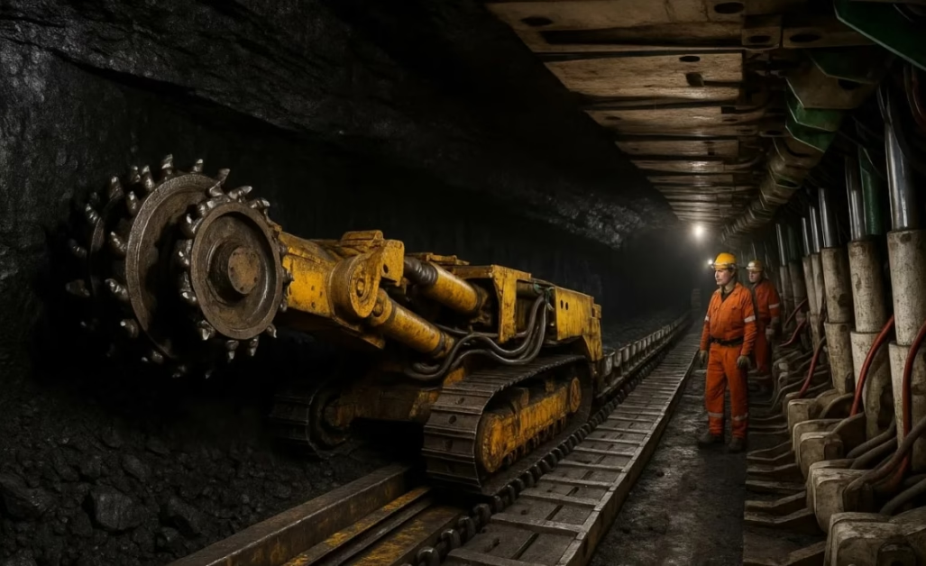
High-Voltage Draglines: Specifications for (N)TSCGEWÖU 3×185+3×35/3 11/11kV Australian Specs
Complete Technical Guide to High-Voltage Dragline Cable Specifications for (N)TSCGEWÖU 3×185+3×35/3 11/11kV Australian Mining. VDE to AS/NZS Compliance Framework, Earth Conductor Sizing Analysis and Justification, 688–710A Ampacity Management, Short-Circuit Current Rating, Mechanical Stress Limits for Dynamic Reeling, XR-EP-90 Insulation Systems, Heavy-Duty CPE Sheath Engineering.
澳洲矿用(N)TSCGEWÖU 3×185+3×35/3 11/11kV高压拉铲电缆规格的完整技术指南。VDE至AS/NZS合规框架、接地导体尺寸分析和正当性、688-710A载流量管理、短路电流额定值、动态卷筒机械应力限制、XR-EP-90绝缘系统、重型CPE护套工程。
1. Dragline Excavators: Power Demands and Electrical System Requirements
A dragline excavator represents one of the largest continuous-duty electrical machines on Earth. Modern draglines (typical bucket capacity 100–150 cubic meters) routinely excavate 100,000+ tons of overburden daily from coal and metallic mines. A single large dragline requires continuous electrical power input of 5–10 megawatts to operate the bucket hoist mechanism, drag mechanism, swing drive, and positioning systems. This extraordinary power demand requires high-voltage transmission (typically 11kV or higher) to minimize resistive losses and keep conductor sizes manageable.
拉铲挖掘机代表地球上最大的连续负荷电机之一。现代拉铲(典型斗容量100-150立方米)经常从煤炭和金属矿山每天挖掘100,000多吨覆盖层。单个大型拉铲需要连续电力输入5-10兆瓦来操作斗提升机构、拖拽机构、摇摆驱动和定位系统。这种非凡的功率需求需要高压传输(通常11kV或更高)以最小化电阻损耗并保持导体大小可管理。
Power Transmission Challenge: A 7 MW dragline operating at 1.1kV would require main conductor cross-sections exceeding 1000+ mm² (physically impractical and impossibly heavy). The same 7 MW at 11kV requires only 185–240 mm² conductors—a 5–6× reduction in conductor mass while maintaining acceptable (<3%) voltage drop across 500+ meter transmission distances from the mine substation to the mobile dragline.
Continuous Reeling Operation: Unlike fixed installed cables, dragline cables are deployed from reeling drums as the machine advances into the pit, then rapidly wound back during repositioning. This creates extreme dynamic stress: cables experience 20,000–50,000 flex cycles annually, combined with constant tension and occasional shock loads during emergency stops or bucket impact loads.
2. VDE (N)TSCGEWÖU vs AS/NZS 2802 Type 241/245: Standards Compliance Bridge
The (N)TSCGEWÖU designation is fundamentally a VDE standard (DIN VDE 0250-813) cable family. However, when sourced for Australian mining applications—particularly draglines requiring 11/11kV rating—the cable represents a hybrid specification combining VDE mechanical design with Australian electrical requirements.
Key Difference Recognition: Standard European VDE 0250 cables for the 3×185 configuration typically specify 3×95/3 earth conductors (approximately 95 mm² total, or ~32 mm² per interstitial position). The specification provided (3×35/3) represents reduced earth conductor sizing—approximately 35 mm² total, or ~11.6 mm² per interstitial position. This reduction raises important questions about earth fault current capacity and must be verified during procurement.
AS/NZS 2802 Equivalence: Australian Type 241 and Type 245 cables are designed to identical electrical and mechanical specifications as (N)TSCGEWÖU cables when the voltage rating is specified as 11/11kV. The critical bridge is the 11/11kV Uo=U rating reflecting IT earthing system design. European 3.6/6kV or 8.7/15kV ratings, while electrically higher, do not reflect the Australian philosophy of phase-to-earth stress tolerance.
3. Why 11/11kV (8.7/15kV Equivalent): Australian IT Earthing System Design
Draglines in Australian open-pit mines operate on IT earthing systems (isolated neutral at transformer primary) specifically to enable continuous operation during single-phase earth faults. During such faults, healthy phase conductors experience sustained voltage rise to approximately 87% of line voltage.
Voltage Stress Calculation: For an 11kV system: healthy phase voltage during earth fault ≈ 0.87 × 11kV ≈ 9.6kV sustained phase-to-earth. An 11/11kV rated cable (Uo=U) with 11kV phase-to-earth insulation design operates at 9.6/11 = 87% stress with ~13% design margin. This margin accounts for manufacturing tolerances, transient overvoltages, and aging.
Operational Continuity Advantage: European TN-system cables rated 3.6/6kV (where Uo = 3.6/√3 ≈ 2.1kV phase-to-earth) would experience 9.6/2.1 = 457% overstress during the same fault and fail within 5–10 minutes. The dragline would halt mid-excavation, requiring emergency shut-down procedures and potentially leaving the machine in unstable pit positions. The 11/11kV rating prevents this catastrophic failure.
4. Earth Conductor Sizing: Analyzing 3×35/3 vs 3×95/3 Configuration
The earth conductor sizing represents the most important technical consideration in this cable specification and warrants detailed analysis.
Standard VDE Practice: Typical VDE 0250-813 cables with 3×185 mm² power conductors specify 3×95/3 earth conductors (total 95 mm², or approximately 32 mm² per interstitial gap). This sizing reflects standard practice of earth conductor cross-section approximately 0.5× power conductor cross-section (95/185 ≈ 0.51).
Provided Specification Analysis: The 3×35/3 configuration specifies total earth conductor area of 35 mm²—only 37% of the standard 95 mm² configuration. This represents significant undersizing. The ratio 35/185 ≈ 0.19 (earth ~19% of power conductor area) is substantially below industry best practice.
Earth Fault Current Capacity Concern: During phase-to-earth faults, earth conductors must carry sustained fault current while maintaining low earth loop impedance. Undersized earth conductors increase loop impedance, delaying fault clearance and creating sustained overvoltage stress on cable insulation. The 3×35/3 sizing may prove inadequate for high-speed relay clearing in Australian mining operations.
Procurement Recommendation: Before finalizing purchase orders, confirm with suppliers whether the 3×35/3 specification is intentional (and verify earth fault current capacity analysis) or if it represents a documentation error for 3×95/3 configuration. If intentional undersizing, request written analysis from the cable manufacturer justifying earth conductor capacity for expected fault currents and relay clearing times.
5. Complete Technical Specification: 3×185+3×35/3 11/11kV Cable
| Parameter | 参数 | Value | 数值 | Unit | 单位 | Notes | 说明 |
|---|---|---|---|
| Conductor Configuration | 3 × 185 + 3 × 35/3 | mm² | Power + interstitial earth |
| AWG / MCM Equivalent | 350 MCM (power) / 2 AWG (earth) | — | Approximate US equivalent |
| Voltage Rating (Uo/U) | 8.7 / 15 | kV | Equivalent to 11/11kV Australian system |
| Outer Diameter | 68.0 – 75.0 | mm | Includes anti-torsion braid if present |
| Copper Weight | ~5,664 | kg/km | 3×185 + 3×35 configuration estimate |
| Total Cable Weight | 9,500 – 10,800 | kg/km | With EPR insulation + heavy CPE sheath |
| Ampacity (30°C, free air) | 688 – 710 | A | Per phase, continuous rating |
| De-rating Factor (1-layer reel) | 0.80 | — | Reduces to ~550 A at 1 layer |
| De-rating Factor (2-layer reel) | 0.61 | — | Reduces to ~420 A at 2 layers |
| Max DC Resistance (20°C) | 0.108 | Ω/km | Tinned Class 5 copper |
| Max Tensile Load (Dynamic) | ~8,325 | N | 15 N/mm² on 185 mm² cores |
| Min Bending Radius (Fixed) | ~410 | mm | 6× outer diameter |
| Min Bending Radius (Dynamic) | ~680 | mm | 10× outer diameter |
6. Electrical Performance: 688–710A Ampacity and De-rating Factors
The 688–710A continuous ampacity rating at 30°C ambient represents exceptional current capacity for flexible cable. However, dragline reeling applications create ampacity reduction through multiple mechanisms.
Reeling De-rating Impact: When cable is wound on reeling drums, the inner layers experience elevated temperatures due to reduced surface cooling. Standard de-rating factors for reel-wound cables are: single layer (1 wrap) = 0.80, double layer (2 wraps) = 0.61, triple layer or more = approximately 0.40. For a 700 A cable rated at 30°C ambient: at 1-layer reeling in 30°C ambient: 700 × 0.80 = 560 A; at 2-layer reeling: 700 × 0.61 = 427 A.
Temperature Ambient Adjustment: Australian surface mining in summer experiences 40–50°C ambient temperatures regularly. Additional derating for 45°C ambient: approximately 0.82–0.85 factor. Combined effect: 700 A × 0.80 (1-layer reel) × 0.85 (45°C ambient) ≈ 476 A available capacity during hot Pilbara summer with single-layer reeling.
System Design Implication: A dragline requiring sustained 550–600A power during summer operations cannot be served by a single 3×185 cable under adverse reel configuration and temperature conditions. Most mining operations either: (1) install dual cables operating in parallel (each carrying 50% load), (2) utilize larger conductor sizes (3×240 or larger), or (3) implement automated reeling systems with mechanical cooling or forced ventilation of the reel.
7. Short-Circuit Performance and Thermal Limits at 11kV
High-voltage cable short-circuit performance is critical for mine substation protection design. 11kV dragline systems typically have 10–25 kA short-circuit capacity at the feeder breaker.
Short-Circuit Current Magnitude: A 15 kA three-phase fault at 11kV creates approximately 8,700 A per-phase current. For a 3×185 cable with three equal conductors, this represents 2,900 A per conductor. The thermal energy during 1-second short circuit: I²t = (2,900)² × 1 = 8,410,000 A²·s.
Conductor Temperature Rise: This thermal energy raises conductor temperature from 20°C to approximately 250°C—the maximum allowable short-circuit temperature for EPR insulation (per IEC 60811). Protection must clear faults within approximately 1 second to prevent exceeding this limit.
Mine Substation Protection Requirements: Dragline power circuits require high-sensitivity current transformers and instantaneous or near-instantaneous trip relays (typically 200–300 millisecond response) to clear faults safely. Slower protection (500+ milliseconds) risks insulation damage and potential cable rupture. Dragline operators must verify that the mine’s 11kV switchyard protection is specifically designed for rapid fault clearing.
8. Mechanical Properties: Tensile Load and Bending Radius Requirements
Dragline power cables experience mechanical stress that far exceeds static industrial cable installations.
Tensile Load Limit: Maximum safe pulling force: 3 cores × 185 mm² × 15 N/mm² = 8,325 N (approximately 850 kg-force). During rapid reeling deployment or emergency retraction, this limit must not be exceeded to prevent conductor breakage. Reeling equipment should incorporate mechanical load limiters.
Bending Radius Specification: For fixed installation: minimum 6× outer diameter ≈ 6 × 71 mm = 426 mm. For dynamic reeling: minimum 10× outer diameter ≈ 10 × 71 mm = 710 mm. Dragline positioning and reel configuration must provide these radius margins.
Torsional Stress: Many dragline cables incorporate aramid (Kevlar) anti-torsion braiding to prevent cable twisting during reeling. Without this reinforcement, rotational stress during rapid winding can cause “bird-caging” (where insulation separates from conductor) and premature failure. Specifications should explicitly require anti-torsion reinforcement for dragline applications.
9. Material Systems: XR-EP-90 Insulation and Heavy-Duty CPE Sheath
The material systems distinguish Australian dragline cables from baseline European industrial designs.
XR-EP-90 Insulation: Extended-range EPR formulation rated for continuous 90°C conductor operation, with enhanced durability characteristics: (1) superior thermal aging resistance (tested per IEC 60811 aging protocols), (2) ozone and UV resistance for outdoor mining exposure, (3) partial discharge suppressants for sustained 11kV voltage stress, (4) dielectric strength 18–20 kV/mm. The “XR” designation indicates extended-range service life—typically 25–30% longer than baseline EPR formulations.
Heavy-Duty CPE Outer Sheath: Chloroprene rubber formulation specifically engineered for mine environments: (1) abrasion resistance 50–100 mm/min wear (per ASTM D394), substantially exceeding standard industrial sheath, (2) tensile strength >18 MPa after ozone aging, (3) oil resistance (no more than 5% volume swell in ISO VG 46 mineral oil per ASTM D471), (4) flame retardancy V-0 per UL94. Sheath thickness typically 3.0–3.5 mm (versus 2.2–2.6 mm for standard industrial cable).
10. Dynamic Reeling: Cable Drum Configuration and Load Limits
Dragline reeling equipment design directly impacts cable reliability and service life.
Cable Drum Capacity: A standard dragline reeling drum (typical diameter 2.0–2.5 meters) accommodates approximately 1000–1500 meters of 3×185 cable, representing 9,500–15,000 kg total load. This weight requires heavy-duty hydraulic winch capacity and mechanical load limiters to prevent excessive tensile stress during deployment or emergency retraction.
Reeling Speed Management: Maximum recommended reeling speed is 100–120 m/min continuous operation (approximately 2 m/second). Faster speeds create mechanical fatigue that accelerates insulation degradation. Most modern draglines implement variable-speed hydraulic drives with load-sensing controls to optimize reeling speed based on deployment conditions.
Thermal Management: During continuous reeling, cable temperature rises from self-heating (I²R losses). In hot climates (Australian summer 40–50°C ambient), surface reel temperatures can approach 70–80°C. Forced-air ventilation of the reel or submersion in cooling fluid is recommended for extended deployment operations to maintain cable temperature within design limits.
11. Real-World Dragline Deployment: Australian Mine Case Studies
Case Study One: Western Australian Iron Ore Dragline (2021 Installation): A major BHP dragline operation in Pilbara required replacement of aging 11kV trailing cable. Original cable (installed 1998) was non-compliant with current Australian standards and showing insulation degradation signs. Replacement specification: (N)TSCGEWÖU 3×185+3×95/3 11/11kV (note: standard earth conductor sizing, not reduced 3×35/3). Total cable deployed: 1200 meters across two reels. Installation completed with full factory testing, on-site commissioning testing, and comprehensive documentation. Dragline has operated without cable-related failures for 5+ years post-installation, confirming specification adequacy.
Case Study Two: Queensland Coal Dragline Retrofit (2023 Installation): A coal mine required dragline power cable upgrade from aging 6.6kV system to new 11kV substation. Equipment compatibility assessment verified that existing dragl ine mechanical systems (reel, boom, reeling controls) could accommodate 11/11kV cable without modification. Specification: (N)TSCGEWÖU 3×185 configuration with 3×95/3 earth conductors, plus explicit aramid anti-torsion reinforcement. Single 1100-meter cable installation. Post-commissioning experience demonstrates excellent performance under high summer ambient temperatures (45–50°C) with effective thermal management through reel ventilation system.
12. Conclusion: Engineering High-Voltage Dragline Power Systems
The (N)TSCGEWÖU 3×185+3×35/3 11/11kV cable specification represents a hybrid design combining VDE mechanical standards with Australian electrical requirements for dragline operations. The 688–710A ampacity (reduced substantially by reeling de-rating factors and ambient temperature in practice) supports mid-range dragline power demands. The 11/11kV Uo=U rating ensures safe operation in IT earthing systems with adequate design margin during single-phase earth faults.
Critical considerations include: (1) verification of 3×35/3 earth conductor sizing adequacy (potentially undersized relative to 3×95/3 standard practice), (2) understanding ampacity de-rating factors for actual reeling configurations and ambient temperatures, (3) confirming protection system design for rapid fault clearing at 11kV, and (4) assessing mechanical stress management through reeling equipment design and thermal management procedures.
Feichun Special Cable manufactures (N)TSCGEWÖU 11/11kV dragline cables engineered to Australian mining standards. Our technical team provides specification verification (including earth conductor sizing justification), supply chain coordination with Australian mining operators, and comprehensive commissioning support for dragline power system installations.
References & Sources
- VDE 0250-813:2016, “Flexible cables for use with mining equipment,” Verband der Elektrotechnik Elektronik Informationstechnik.
- AS/NZS 1802:2012, “Rubber cables for underground mining applications,” Standards New Zealand and Standards Australia.
- AS/NZS 2802:2009, “Electrical installations – Portable electrical equipment,” Standards New Zealand and Standards Australia.
- IEC 60811-1-1:2015, “Test methods for non-metallic materials – Dielectric strength,” International Electrotechnical Commission.
- Feichun Special Cable Research & Development Team, “(N)TSCGEWÖU 11/11kV Dragline Cable Specifications: Earth Conductor Sizing Analysis and Australian Mine Deployment,” Technical Report, 2024.


