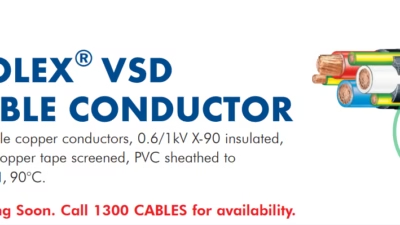
What is VAROLEX® VSD/EMC 3C+3E Cable?
Variable Speed Drive Cable with Copper Tape Screening for Superior Electromagnetic Compatibility in Industrial Motor Control Applications
Quick Specifications
Introduction to VSD/EMC Cable Technology
The VAROLEX® VSD/EMC cable represents a specialized engineering solution designed specifically for variable speed drive (VSD) applications where electromagnetic compatibility (EMC) is a critical operational requirement. Manufactured by Anhui Feichun Special Cable Co., Ltd (安徽飞纯特种电缆有限公司), this cable incorporates a symmetrical 3C+3E (three core plus three earth) configuration with copper tape screening to effectively mitigate electromagnetic interference (EMI) emissions that are inherent to modern pulse-width modulation (PWM) drive systems.
Variable frequency drives operate by generating high-frequency switching pulses to control motor speed and torque, producing voltage rise times in the order of 100 nanoseconds. This fast-switching characteristic creates significant electromagnetic emission across a frequency spectrum extending from 150kHz to beyond 30MHz. Without proper cable screening and earthing, these emissions can interfere with nearby sensitive electronic equipment, communication systems, and control instrumentation. The VAROLEX® VSD/EMC cable addresses this challenge through its integrated copper tape screen and symmetrical earth conductor arrangement, providing a low-impedance return path for high-frequency common-mode currents.
Primary Technical Parameters
The Science of EMC in Variable Speed Drives
Understanding the electromagnetic compatibility requirements of VSD installations requires examining the fundamental mechanisms by which interference is generated and propagated. Modern variable frequency drives utilize insulated gate bipolar transistors (IGBTs) or similar power semiconductors to synthesize a variable-frequency output from a fixed-frequency supply. The switching frequencies typically range from 2kHz to 16kHz, but the rapid voltage transitions during each switching event contain harmonic components extending well into the megahertz range.
The electromagnetic interference generated by VSD systems manifests in two primary modes. Differential-mode emissions travel along the power conductors as current loops between phases, while common-mode emissions flow through all conductors simultaneously and return through ground paths. The common-mode component is particularly problematic because it seeks any available return path, potentially flowing through motor bearings (causing bearing fluting and premature failure), through building ground systems (creating ground loops), or radiating from the motor cable as electromagnetic waves (causing radio-frequency interference).
According to technical resources from cranecable.com, VFD cables with proper screening and symmetrical conductor arrangement are essential for industrial motor control applications where electromagnetic interference must be minimized to protect sensitive control systems and prevent operational disruptions in port machinery and crane equipment.
The 3C+3E Symmetrical Design Principle
The VAROLEX® cable’s 3C+3E configuration represents the industry-recognized optimal design for VSD motor cables. In this arrangement, three phase conductors (3C) are positioned symmetrically with three earth conductors (3E) placed in the interstices between the phase cores. This symmetrical geometry serves multiple critical functions in EMC management.
First, the symmetrical arrangement ensures that the magnetic fields generated by each phase conductor are balanced and substantially cancel each other in the far field, reducing overall magnetic emission. Second, the interstitial earth conductors provide a low-impedance, distributed return path for high-frequency ground currents, keeping these currents local to the cable rather than allowing them to propagate through the facility ground system. Third, the earth conductors positioned adjacent to each phase conductor minimize the loop area for high-frequency currents, directly reducing inductive coupling and radiated emissions.
EMC Performance Characteristics
Cable Construction Analysis
The VAROLEX® VSD/EMC cable construction follows a carefully engineered layer sequence, with each component contributing specific electrical, mechanical, or protective functions. Understanding this construction enables proper specification, installation, and maintenance of these cables in VSD applications.
Construction Layer Sequence
Conductor
Plain copper, circular stranded, Class 2Insulation
X-90 Cross-linked polyethylene (XLPE)Earth Conductors
3× interstitial copper, combined as specifiedInner Bedding
PVC compound for core stabilizationElectromagnetic Screen
Copper tape wrap for EMC shieldingOuter Sheath
PVC compound, black standardConductor System Analysis
The VAROLEX® cable utilizes plain copper conductors rather than flexible stranded construction, as indicated in the product specifications. This design choice reflects the cable’s intended application in fixed installations rather than mobile or reeling applications. The Class 2 stranded copper construction provides adequate flexibility for routing through cable trays and conduits while maintaining excellent electrical conductivity. Conductor sizes range from 2.5mm² through 300mm², covering the full spectrum of VSD motor applications from fractional horsepower fans to large industrial drives exceeding 300kW.
The earth conductor sizing follows a progressive relationship with the phase conductor cross-section. For the smallest 2.5mm² configuration, a single earth conductor is utilized since split earth construction is not feasible at this size. From 4mm² upward, three symmetrically-positioned earth conductors are incorporated, with combined cross-sectional areas scaled to maintain appropriate earth fault current capacity and low-impedance high-frequency return paths.
Technical documentation from amplexmining.com.au confirms that copper screening systems in industrial cables provide both electrical screening and mechanical protection, with the copper construction providing low-resistance earth paths essential for safety and electromagnetic compatibility in demanding operational environments.
X-90 Insulation Technology
The X-90 designation refers to cross-linked polyethylene (XLPE) insulation rated for 90°C continuous operation. Cross-linking transforms standard polyethylene from a thermoplastic material into a thermoset compound through chemical or radiation processing. This transformation creates intermolecular bonds that dramatically improve the material’s thermal, mechanical, and electrical properties.
The cross-linked molecular structure prevents the insulation from softening at elevated temperatures, maintaining dimensional stability and electrical properties at operating temperatures that would cause standard PVC or thermoplastic polyethylene to deform. The 90°C rating provides significant headroom above typical motor and drive operating temperatures, ensuring reliable long-term performance even under sustained overload conditions. Additionally, XLPE exhibits excellent dielectric properties, with low dissipation factor and high insulation resistance that remain stable across the operating temperature range.
Complete Technical Specifications
| Nom. Cond. Area (mm²) | Insul. Thick (mm) | Combined Earth (mm²) | Dia. Over Screen (mm) | Overall Dia. (mm) | Mass (kg/100m) | Product Code | Availability |
|---|---|---|---|---|---|---|---|
| 2.5 | 0.7 | 2.5* | 10.9 | 14.6 | 32 | FTDP07AA003 | Stock |
| 4 | 0.7 | 4.5 | 13.0 | 16.6 | 44 | FTDP09AA003 | Stock |
| 6 | 0.7 | 4.5 | 13.8 | 17.5 | 51 | FTDP11AA003 | Stock |
| 10 | 0.7 | 4.5 | 14.8 | 18.5 | 62 | FTDP13AA003 | Stock |
| 16 | 0.8 | 7.5 | 17.0 | 20.6 | 86 | FTDP15AA003 | Stock |
| 25 | 0.9 | 12 | 19.2 | 22.8 | 121 | FTDC17AA003 | Stock |
| 35 | 0.9 | 18 | 21.9 | 25.6 | 160 | FTDC18AA003 | Stock |
| 50 | 1.0 | 30 | 25.1 | 28.8 | 211 | FTDC19AA003 | Stock |
| 70 | 1.1 | 30 | 28.1 | 32.0 | 277 | FTDC20AA003 | Stock |
| 95 | 1.1 | 48 | 33.9 | 38.0 | 390 | FTDC22AA003 | Stock |
| 120 | 1.2 | 48 | 38.9 | 43.2 | 467 | FTDP23AA003 | Stock |
| 150 | 1.4 | 75 | 42.6 | 47.3 | 585 | FTDP24AA003 | Stock |
| 185 | 1.6 | 75 | 47.5 | 52.0 | 711 | FTDP25AA003 | Stock |
| 240 | 1.7 | 105 | 53.6 | 58.9 | 918 | FTDP26AA003 | MTO |
| 300 | 1.8 | 150 | 59.6 | 65.2 | 1154 | FTDP27AA003 | MTO |
Table Notes: *For 2.5mm² size, split earth configuration is not feasible; a single earth conductor is utilized. This product range does not utilize flexible (Class 5) conductors. MTO = Made to Order.
Color Options
Black (Standard Stock)
Add the 4-letter code to the end of the product code to place an order
Parameter Comparison: Earth Conductor Scaling
The relationship between phase conductor size and combined earth conductor area demonstrates careful engineering to maintain appropriate earth fault capacity while optimizing cable diameter and weight. The following analysis illustrates the earth-to-phase conductor ratio progression across the product range.
Small Conductors2.5mm² – 10mm²
Combined earth area approximately equals phase conductor area for optimal balance.
Medium Conductors16mm² – 70mm²
Earth conductor sizing optimized for thermal and mechanical constraints.
Large Conductors95mm² – 300mm²
Adequate earth fault capacity maintained with cable diameter optimization.
Application Scenarios
The VAROLEX® VSD/EMC cable serves a broad range of industrial applications where variable speed drives control motor operations. The cable’s EMC properties make it particularly valuable in environments with sensitive electronic equipment or strict electromagnetic emission requirements.
Industrial Manufacturing
Manufacturing facilities extensively utilize VSD technology for process optimization, with applications including conveyor systems, pump stations, fan and blower controls, and machine tool spindles. In these environments, the VAROLEX® cable prevents drive-generated interference from affecting programmable logic controllers (PLCs), human-machine interfaces (HMIs), and precision measurement instrumentation that often operate in close proximity to motor circuits.
Industrial cable applications documented at reelingcable.com confirm that properly screened cables with symmetrical earth arrangements are essential for material handling systems, cranes, and conveyor equipment where electromagnetic interference could disrupt sensitive control systems or cause operational faults in port and industrial environments.
Water and Wastewater Treatment
Water treatment facilities represent one of the most significant applications for VSD technology, with large pumps, aerators, and blowers benefiting substantially from variable speed control for energy optimization. These facilities often incorporate extensive SCADA (Supervisory Control and Data Acquisition) systems with distributed sensors and communication networks that are vulnerable to electromagnetic interference. The VAROLEX® cable’s screening capability ensures reliable 24/7 operation of both power and control systems.
HVAC and Building Services
Modern commercial buildings increasingly specify VSD-controlled HVAC systems for energy efficiency and comfort optimization. The cable is particularly suitable for applications including chiller plants, air handling units, cooling towers, and variable air volume systems. Building automation systems and BACnet/Modbus communication networks benefit from the reduced electromagnetic emission levels that properly installed VSD/EMC cables provide.
Mining and Heavy Industry
Mining operations utilize VSDs for ventilation fans, conveyor drives, crushers, and material handling equipment. The demanding nature of mining environments requires cables that combine EMC performance with mechanical durability. As documented by industry sources at miningcable.cl, properly specified cables for VSD applications in mining must withstand harsh environmental conditions while maintaining electromagnetic compatibility to prevent interference with safety-critical monitoring and control systems.
Installation Guidelines for EMC Performance
Achieving the designed EMC performance from the VAROLEX® VSD/EMC cable requires proper installation practices that maintain the integrity of the screening system and minimize additional electromagnetic coupling paths. The following guidelines reflect industry best practices for VSD cable installations.
Screen Termination
The copper tape screen must be terminated using 360-degree bonding techniques at both the drive and motor ends. This requires removing the outer sheath and utilizing appropriate EMC cable glands that clamp around the full circumference of the screen. Point contact or pigtail terminations significantly degrade high-frequency screening effectiveness and should be avoided. The screen bonding surface must be clean and free of oxidation to ensure low-impedance connection to the drive enclosure and motor frame.
Routing and Separation
VSD motor cables should be physically separated from sensitive signal and communication cables by a minimum distance of 200mm (8 inches). Where crossings are unavoidable, cables should cross at 90-degree angles to minimize coupling length. The motor cable should be routed close to grounded metallic surfaces (cable trays, structural steel, or equipment enclosures) rather than suspended in free air, as proximity to ground planes reduces electromagnetic emission. Cable lengths should be minimized to reduce both inductance and capacitance, though avoiding excessive spare cable coiled at termination points is equally important.
According to technical resources from Feichun Cable, proper cable installation practices are essential for achieving designed EMC performance, with particular attention required for screen termination methods and cable routing to maintain electromagnetic compatibility in industrial VSD applications.
Standards Compliance
The VAROLEX® VSD/EMC cable is manufactured in compliance with AS/NZS 5000.1, the Australian and New Zealand standard for electric cables — polymeric insulated. This standard establishes requirements for construction, materials, dimensions, and electrical properties that ensure consistent performance across production batches and compatibility with local installation practices.
Additionally, installations utilizing this cable should be designed to meet the requirements of IEC 61800-3 (EN 61800-3), which specifies EMC requirements and test methods for power drive systems. This standard defines emission limits and immunity requirements that vary based on the installation environment category, with more stringent requirements applying to residential and light industrial environments compared to heavy industrial settings.
Technical References and External Resources
Industry Authority Sources
Technical resources for industrial cable applications including reeling cables, crane cables, and port machinery power solutions.
Australian mining cable standards and specifications including AS/NZS compliant screened and trailing cables for demanding environments.
South American mining cable resources with technical documentation for VSD and EMC applications in industrial and mining sectors.
Specialized port machinery cable solutions including VFD motor cables, crane power cables, and EMC-compliant installations.
Official manufacturer website for Anhui Feichun Special Cable Co., Ltd with complete product specifications and technical support.
Request Technical Support
Contact our engineering team for VSD cable sizing calculations, EMC installation guidance, or custom specification requirements.