industrial automation cable

Feichun FLEXIFESTOON® PV-FLAT UL (600V, UL VW-1/CSA FT4 Certified) North American Industrial Festoon Control Cables: Extended Temperature 105°C PVC Compound Formulation for High-Flexibility Automation Systems (600V Rated Voltage, 2000V Dielectric Test, UL VW-1 Vertical Flame Test & CSA FT4 Compliance, −40°C to +105°C Arctic-to-Thermal Service Temperature Envelope, High-Flexibility Dynamic Dual-Axis Motion Architecture, 120 m/min Certified Speed Rating for Solar Tracking & Industrial Robotic Systems, 18 Complete Product SKU Configurations 4–12 Cores, AWG 2–16 Conductor Range, UL Festoon/AWM 105°C & CSA Festoon 105°C Dual Certification, Yellow/Black PVC Sheath Options, Oil-Resistant & Cold-Resistant Formulation, RoHS/CE Compliance): Comprehensive Technical Analysis Integrating Polymer Thermal Stability Chemistry, Extended Temperature PVC Insulation Science, North American UL/CSA Certification Standards, Industrial Automation System Integration, & Comparative Performance Benchmarking Against European & Asian Festoon Cable Specifications Industrial automation infrastructure across North America—Variable Frequency Drive (VFD) control systems, robotic manufacturing environments, solar tracking platforms, material handling systems, and Arctic region installations—demands electrical cabling fundamentally different from standard commodity industrial specifications: sustained elevated conductor temperatures (up to +90°C continuous, +105°C short-duration thermal transients) from high-power motor control electronics and concentrated solar heating on exposed cable trays, extreme thermal cycling from sub-arctic nighttime minimums (−40 °C arctic installations, −20 °C extended winter operations) to +105 °C daytime peak heating, inducing expansion-contraction stress on PVC insulation polymer chains and accelerating mechanical fatigue at conductor-insulation interfaces, mandatory UL/CSA dual certification requirements across North American electrical codes (National Electrical Code NEC, Canadian Electrical Code CEC, plant-level requirements from IEEE/NFPA standards), and continuous mechanical flexure from dual-axis motion systems (5–20 million bending cycles per year from solar tracker repositioning, robotic arm cycling, and conveyor system reeling). Conventional industrial control cables (600V commodity PVC, 60–70 °C temperature rating) fail catastrophically under sustained 90–105 °C thermal stress, suffering rapid insulation embrittlement through free-radical oxidation at elevated temperature, accelerated plasticizer migration (DHF—dioctyl hexanedioate, diisononyl cyclohexane-1,2-dicarboxylate) leading to tensile strength collapse, and premature conductor strand fracture under fatigue-assisted creep failure mechanisms. FLEXIFESTOON® PV-FLAT UL (600V, 105°C) represents a specialized North American industrial engineering platform achieving simultaneous optimization across the complete UL/CSA certified voltage spectrum (600V nominal—matching standard North American three-phase motor control and solar inverter voltage ratings across IEEE 1547 distributed generation systems) through proprietary extended-temperature PVC formulation chemistry incorporating hindered amine light stabilizers (HALS), hindered phenolic antioxidants, and advanced thermal stabilization package (4.5–6.0 wt% premium additive loading vs. commodity 0.5–1.0 wt%) delivering sustained mechanical integrity across −40 to +105 °C continuous operational envelope, UL VW-1 vertical flame propagation certification and CSA FT4 flame retardancy rating ensuring fire safety across hazardous industrial zones, high-flexibility festoon architecture (5× outer diameter minimum bending radius per DIN VDE 0298) enabling integrated motion control for dual-axis solar trackers and 6-axis robotic arm systems, yellow and black sheath options optimizing electrical safety visibility and thermal properties, and comprehensive 18-SKU product portfolio spanning 4–12 core configurations and AWG 2–16 conductor range—providing industrial automation engineers and renewable energy system integrators with specialized festoon cabling optimized for North American UL/CSA regulated markets across Arctic mining operations, tropical solar farms, temperate manufacturing facilities, and global deployment requiring extended-temperature performance and dual North American certification across 10–15 year system operational lives.

FLEXIFESTOON® PV-FLAT UL

Feichun FLEXIFESTOON® PV-FLAT UL (600V, UL VW-1/CSA FT4 Certified) North American Industrial Festoon Control Cables: Extended Temperature 105°C PVC Compound Formulation for High-Flexibility Automation Systems (600V Rated Voltage, 2000V Dielectric Test, UL VW-1 Vertical Flame Test & CSA FT4 Compliance, −40°C to +105°C Arctic-to-Thermal Service Temperature Envelope, High-Flexibility Dynamic Dual-Axis Motion Architecture, 120 m/min Certified Speed Rating for Solar Tracking & Industrial Robotic Systems, 18 Complete Product SKU Configurations 4–12 Cores, AWG 2–16 Conductor Range, UL Festoon/AWM 105°C & CSA Festoon 105°C Dual Certification, Yellow/Black PVC Sheath Options, Oil-Resistant & Cold-Resistant Formulation, RoHS/CE Compliance): Comprehensive Technical Analysis Integrating Polymer Thermal Stability Chemistry, Extended Temperature PVC Insulation Science, North American UL/CSA Certification Standards, Industrial Automation System Integration, & Comparative Performance Benchmarking Against European & Asian Festoon Cable Specifications Industrial automation infrastructure across North America—Variable Frequency Drive (VFD) control systems, robotic manufacturing environments, solar tracking platforms, material handling systems, and Arctic region installations—demands electrical cabling fundamentally different from standard commodity industrial specifications: sustained elevated conductor temperatures (up to +90°C continuous, +105°C short-duration thermal transients) from high-power motor control electronics and concentrated solar heating on exposed cable trays, extreme thermal cycling from sub-arctic nighttime minimums (−40 °C arctic installations, −20 °C extended winter operations) to +105 °C daytime peak heating, inducing expansion-contraction stress on PVC insulation polymer chains and accelerating mechanical fatigue at conductor-insulation interfaces, mandatory UL/CSA dual certification requirements across North American electrical codes (National Electrical Code NEC, Canadian Electrical Code CEC, plant-level requirements from IEEE/NFPA standards), and continuous mechanical flexure from dual-axis motion systems (5–20 million bending cycles per year from solar tracker repositioning, robotic arm cycling, and conveyor system reeling). Conventional industrial control cables (600V commodity PVC, 60–70 °C temperature rating) fail catastrophically under sustained 90–105 °C thermal stress, suffering rapid insulation embrittlement through free-radical oxidation at elevated temperature, accelerated plasticizer migration (DHF—dioctyl hexanedioate, diisononyl cyclohexane-1,2-dicarboxylate) leading to tensile strength collapse, and premature conductor strand fracture under fatigue-assisted creep failure mechanisms. FLEXIFESTOON® PV-FLAT UL (600V, 105°C) represents a specialized North American industrial engineering platform achieving simultaneous optimization across the complete UL/CSA certified voltage spectrum (600V nominal—matching standard North American three-phase motor control and solar inverter voltage ratings across IEEE 1547 distributed generation systems) through proprietary extended-temperature PVC formulation chemistry incorporating hindered amine light stabilizers (HALS), hindered phenolic antioxidants, and advanced thermal stabilization package (4.5–6.0 wt% premium additive loading vs. commodity 0.5–1.0 wt%) delivering sustained mechanical integrity across −40 to +105 °C continuous operational envelope, UL VW-1 vertical flame propagation certification and CSA FT4 flame retardancy rating ensuring fire safety across hazardous industrial zones, high-flexibility festoon architecture (5× outer diameter minimum bending radius per DIN VDE 0298) enabling integrated motion control for dual-axis solar trackers and 6-axis robotic arm systems, yellow and black sheath options optimizing electrical safety visibility and thermal properties, and comprehensive 18-SKU product portfolio spanning 4–12 core configurations and AWG 2–16 conductor range—providing industrial automation engineers and renewable energy system integrators with specialized festoon cabling optimized for North American UL/CSA regulated markets across Arctic mining operations, tropical solar farms, temperate manufacturing facilities, and global deployment requiring extended-temperature performance and dual North American certification across 10–15 year system operational lives.
Prysmian CORDAFLEX (SMK), Lapp ÖLFLEX CRANE NSHTÖU, Nexans RHEYFLAT-N, TKD TROMMELFLEX PUR-HF, Draka BUFLEX XTREME, and Aristoncavi PANZERLITE spreader cables — with honest engineering analysis and practical selection guidance.

NGFLGÖU-J,(N)TSCGEWÖU,(N)SSHÖU 3×95+3×16/3,(N)TSCGEWÖU,Prysmian CORDAFLEX (SMK),Lapp ÖLFLEX CRANE NSHTÖU,Nexans RHEYFLAT-N,TKD TROMMELFLEX PUR-HF,Draka BUFLEX XTREME, Reeling cable, Mining cable – Guide (2026)

Prysmian CORDAFLEX (SMK), Lapp ÖLFLEX CRANE NSHTÖU, Nexans RHEYFLAT-N, TKD TROMMELFLEX PUR-HF, Draka BUFLEX XTREME, and Aristoncavi PANZERLITE spreader cables — with honest engineering analysis and practical selection guidance.
Full technical breakdown Lapp ÖLFLEX CLASSIC 110 CY 300/500V: shielded multi-core control cable for CNC machine tools, conveyor systems, automation panels. Characteristic transparent PVC outer sheath allows visual inspection of tinned copper braid shield integrity. "CY" designates copper shield (copperScreen) protecting low-voltage control signals from electromagnetic interference (EMC) from nearby power cables, frequency converters, welding equipment, RF sources. Standard configurations: 2–100 cores, 0.5–35 mm² sections with digital marking (black cores + white numbers) + yellow-green earth. Conductor class 5 per VDE 0295 (maximum flexibility), min. bending radius 20× OD in mobile applications. Special PVC insulation (Lapp composition) provides -5°C to +70°C (mobile) / -40°C to +80°C (fixed). Flame retardant IEC 60332-1-2 (self-extinguishing). Tinned copper braid shield density ~85%, effective EMI suppression 50 Hz to several MHz. Transparent sheath is Lapp trademark — allows visual shield inspection without cutting. Russian alternatives: КГВВЭ (usually black/grey sheath, color-coded cores), МКЭШВ (small sections). European standard YSLYCY-JZ from Helukabel, TKD, Faber. FeiChun YSLYCY-JZ — full drop-in equivalent with transparent PVC, digital marking, 85%+ copper braid.

ÖLFLEX CLASSIC 110 CY Экранированный контрольный кабель: прозрачная ПВХ и медная оплётка для защиты от ЭМС — FeiChun YSLYCY-JZ, аналоги Lapp

Full technical breakdown Lapp ÖLFLEX CLASSIC 110 CY 300/500V: shielded multi-core control cable for CNC machine tools, conveyor systems, automation panels. Characteristic transparent PVC outer sheath allows visual inspection of tinned copper braid shield integrity. “CY” designates copper shield (copperScreen) protecting low-voltage control signals from electromagnetic interference (EMC) from nearby power cables, frequency converters, welding equipment, RF sources. Standard configurations: 2–100 cores, 0.5–35 mm² sections with digital marking (black cores + white numbers) + yellow-green earth. Conductor class 5 per VDE 0295 (maximum flexibility), min. bending radius 20× OD in mobile applications. Special PVC insulation (Lapp composition) provides -5°C to +70°C (mobile) / -40°C to +80°C (fixed). Flame retardant IEC 60332-1-2 (self-extinguishing). Tinned copper braid shield density ~85%, effective EMI suppression 50 Hz to several MHz. Transparent sheath is Lapp trademark — allows visual shield inspection without cutting. Russian alternatives: КГВВЭ (usually black/grey sheath, color-coded cores), МКЭШВ (small sections). European standard YSLYCY-JZ from Helukabel, TKD, Faber. FeiChun YSLYCY-JZ — full drop-in equivalent with transparent PVC, digital marking, 85%+ copper braid.
Full technical breakdown Aristoncavi PANZERLITE 0.6/1 kV: revolutionary lightweight polyurethane cable for Ship-to-Shore basket operation. "LITE" (Lightweight) reflects core philosophy: every kg of weight saved directly reduces kinetic energy of 50–80 m free fall, cuts impact shock on basket, prevents tangling in rings, radically lowers peak tension in central Kevlar strength element. Configuration 44G2.5 or 54G2.5: multiple thin cores (44–54 cores) × 2.5 mm² each, powering spreader motors + control signals. Mass 25–35% lower than standard spreader cables of same section (thin-wall insulation, light PUR sheath). Unique anti-twist wrap between cores and sheath acts as mechanical damper: during unwinding, actively returns cable to natural straight state, prevents spiral deformation and overtwist. Central Kevlar (aramid) strength element, 18–22 kN tensile, carries full suspended cable weight (80 m). EPR insulation, halogen-free yellow PUR sheath, flame retardant IEC 60332-3 + low smoke ISO 1182. OD ~16–20 mm, weight ~0.65–0.85 kg/m (30% lighter than CORDAFLEX K). FeiChun Lightweight Basket Cable — drop-in equivalent with anti-twist innovation and perfect weight-strength balance.

PANZERLITE Облегченный кабель для крановых корзин STS: инновационная конструкция против скручивания — FeiChun Lightweight Basket Cable, аналог Aristoncavi

Full technical breakdown Aristoncavi PANZERLITE 0.6/1 kV: revolutionary lightweight polyurethane cable for Ship-to-Shore basket operation. “LITE” (Lightweight) reflects core philosophy: every kg of weight saved directly reduces kinetic energy of 50–80 m free fall, cuts impact shock on basket, prevents tangling in rings, radically lowers peak tension in central Kevlar strength element. Configuration 44G2.5 or 54G2.5: multiple thin cores (44–54 cores) × 2.5 mm² each, powering spreader motors + control signals. Mass 25–35% lower than standard spreader cables of same section (thin-wall insulation, light PUR sheath). Unique anti-twist wrap between cores and sheath acts as mechanical damper: during unwinding, actively returns cable to natural straight state, prevents spiral deformation and overtwist. Central Kevlar (aramid) strength element, 18–22 kN tensile, carries full suspended cable weight (80 m). EPR insulation, halogen-free yellow PUR sheath, flame retardant IEC 60332-3 + low smoke ISO 1182. OD ~16–20 mm, weight ~0.65–0.85 kg/m (30% lighter than CORDAFLEX K). FeiChun Lightweight Basket Cable — drop-in equivalent with anti-twist innovation and perfect weight-strength balance.
Full technical breakdown Draka CORDAFLEX (K) 0.6/1 kV: specialized low-voltage polyurethane cable for Ship-to-Shore (STS) container crane spreaders. "K" (German Korb = basket) = gravity-fed basket operation: cable drops freely into circular basket on spreader, forming perfect rings without tangling. Bright yellow PUR sheath = international port safety standard (maximum visibility for dock workers). Configuration 54G3.5 or 44G3.5: multiple thin cores (44–54 cores) × 3.5 mm² each, powering spreader motors (~50–70 kW) + transmitting control signals (twistlock solenoids, cameras, weight sensors). Kevlar (aramid) central strength element carries full weight of suspended cable (50–80 m free hang), unloading copper strands from mechanical stress. EPR insulation, halogen-free PUR extrusion, flame retardant IEC 60332-3 + low smoke ISO 1182 (critical for ship decks). OD ~19–24 mm, weight ~0.9–1.2 kg/m, current ~110–140 A. FeiChun Spreader Basket Cable — drop-in equivalent with perfect PUR extrusion ensuring natural gravity fall into spreader baskets (Bromma, RAM, Stinis, ZPMC).

CORDAFLEX (K) Расшифровка: Желтый полиуретановый кабель для спредеров STS кранов — FeiChun Spreader Basket Cable, аналог Draka/Prysmian

Full technical breakdown Draka CORDAFLEX (K) 0.6/1 kV: specialized low-voltage polyurethane cable for Ship-to-Shore (STS) container crane spreaders. “K” (German Korb = basket) = gravity-fed basket operation: cable drops freely into circular basket on spreader, forming perfect rings without tangling. Bright yellow PUR sheath = international port safety standard (maximum visibility for dock workers). Configuration 54G3.5 or 44G3.5: multiple thin cores (44–54 cores) × 3.5 mm² each, powering spreader motors (~50–70 kW) + transmitting control signals (twistlock solenoids, cameras, weight sensors). Kevlar (aramid) central strength element carries full weight of suspended cable (50–80 m free hang), unloading copper strands from mechanical stress. EPR insulation, halogen-free PUR extrusion, flame retardant IEC 60332-3 + low smoke ISO 1182 (critical for ship decks). OD ~19–24 mm, weight ~0.9–1.2 kg/m, current ~110–140 A. FeiChun Spreader Basket Cable — drop-in equivalent with perfect PUR extrusion ensuring natural gravity fall into spreader baskets (Bromma, RAM, Stinis, ZPMC).
Complete specifications and comparative pricing analysis JZ-600 7G16 mm² (also searched as JZ600 7x16 or OZ-600 7G16) 0.6/1 kV: OD 24.5–26.5 mm, weight ~1,630 kg/km, copper index ~1,075 kg/km, current 76 A base @ 30°C (actual ~43 A with 7-core derating 0.57), copper class 5, PVC TI2 insulation, PVC TM2 outer (black, UV resistant), bending 7.5–10×OD flexing, temp -5/+80°C flexing. Designation decoding: letter-by-letter German marking breakdown. Pricing: Helukabel/Lapp original €180–280/km, Feichun FC-JZ600 €85–140/km (50–60% savings). DIN VDE 0285-525-2-51. EAC, GOST-R, CE certified. TCO calculator for overhead cranes, CNC machines, and control cabinets.

Характеристики и цена: JZ-600 7G16 mm² 0.6/1 kV — гибкий контрольно-силовой кабель для европейских станков и кранов

Complete specifications and comparative pricing analysis JZ-600 7G16 mm² (also searched as JZ600 7×16 or OZ-600 7G16) 0.6/1 kV: OD 24.5–26.5 mm, weight ~1,630 kg/km, copper index ~1,075 kg/km, current 76 A base @ 30°C (actual ~43 A with 7-core derating 0.57), copper class 5, PVC TI2 insulation, PVC TM2 outer (black, UV resistant), bending 7.5–10×OD flexing, temp -5/+80°C flexing. Designation decoding: letter-by-letter German marking breakdown. Pricing: Helukabel/Lapp original €180–280/km, Feichun FC-JZ600 €85–140/km (50–60% savings). DIN VDE 0285-525-2-51. EAC, GOST-R, CE certified. TCO calculator for overhead cranes, CNC machines, and control cabinets.
Full decoding of RTS (Robotic/Torsion Standard) conductor class for ultra-fine stranded copper: wire diameter ≤0.10–0.15 mm, 5–10M+ flex cycles, min bend radius 5×OD dynamic, travel speed up to 10 m/s in drag chains. Letter-by-letter decoding of (N)TSCGEWÖU (also searched as NTSCGEWOEU or NTSCGEWOU). Comparison Class 5 → Class 6 → RTS/special. Construction: short-pitch bunch-in-bunch stranding, pressure-extruded sheath, central tension member. Why Class 5 fails in energy chains: bird-caging, wire fracture, contact loss. Sample spec 4G1.5 mm² RTS (300/500 V). Pricing: Igus €8–14/m, Lapp €6–12/m vs Feichun FC-RTS €2.5–5.5/m (45–60% savings). 5-year TCO for 6-axis robot cells. EAC, GOST-R, CE, UL certified.

Проводник медный сверхтонкий многожильный, класс „RTS”: почему он лучше IEC 60228 / DIN VDE 0295 Класс 5

Full decoding of RTS (Robotic/Torsion Standard) conductor class for ultra-fine stranded copper: wire diameter ≤0.10–0.15 mm, 5–10M+ flex cycles, min bend radius 5×OD dynamic, travel speed up to 10 m/s in drag chains. Letter-by-letter decoding of (N)TSCGEWÖU (also searched as NTSCGEWOEU or NTSCGEWOU). Comparison Class 5 → Class 6 → RTS/special. Construction: short-pitch bunch-in-bunch stranding, pressure-extruded sheath, central tension member. Why Class 5 fails in energy chains: bird-caging, wire fracture, contact loss. Sample spec 4G1.5 mm² RTS (300/500 V). Pricing: Igus €8–14/m, Lapp €6–12/m vs Feichun FC-RTS €2.5–5.5/m (45–60% savings). 5-year TCO for 6-axis robot cells. EAC, GOST-R, CE, UL certified.
Complete technical datasheet Chinese equivalent Prysmian PROTOLON (SB) NTSCGEWOEU 6/10 kV: reeling cable mobile heavy-duty equipment — port gantry cranes (RTG/STS/RMG), open-pit excavators, stacker-reclaimers, spreaders, draglines, bucket-wheel excavators. Configuration 3×50 mm² power + 2×(25/2) mm² earth + 1×16 mm² control (st). Rated voltage 6/10 kV (max. 7.2/12 kV). Outer diameter ~45.0–49.5 mm, weight ~3,650–3,800 kg/km, copper index ~1,834 kg/km. Current capacity ~183 A @ 30°C. Min. bending radius 12–15×OD. Travel speed up to 120–240 m/min. Max. tensile force ~2,250 N (15 N/mm² copper, up to 30 N/mm² acceleration per DIN VDE 0298-3). Temperature -35°C to +80°C flexing, -50°C to +80°C fixed. EPR/HEPR insulation with semiconductive field-control screens 6/10 kV, dual outer sheath PCP/PUR — abrasion/oil/UV/ozone/flame resistant (EN 60332-1-2). Additional testing: reversed bending, torsional stress, roller bending per DIN VDE 0250-813. Russian GOST equivalent КГЭШ-Т 6/10 kV. EAC, GOST-R/-K/-B, Fire Certificate certified.

Аналог PROTOLON (SB): кабель барабанный 3×50+2×25/2+1×16st 6/10 kV — полный технический паспорт (Feichun Cable, Китай)

Complete technical datasheet Chinese equivalent Prysmian PROTOLON (SB) NTSCGEWOEU 6/10 kV: reeling cable mobile heavy-duty equipment — port gantry cranes (RTG/STS/RMG), open-pit excavators, stacker-reclaimers, spreaders, draglines, bucket-wheel excavators. Configuration 3×50 mm² power + 2×(25/2) mm² earth + 1×16 mm² control (st). Rated voltage 6/10 kV (max. 7.2/12 kV). Outer diameter ~45.0–49.5 mm, weight ~3,650–3,800 kg/km, copper index ~1,834 kg/km. Current capacity ~183 A @ 30°C. Min. bending radius 12–15×OD. Travel speed up to 120–240 m/min. Max. tensile force ~2,250 N (15 N/mm² copper, up to 30 N/mm² acceleration per DIN VDE 0298-3). Temperature -35°C to +80°C flexing, -50°C to +80°C fixed. EPR/HEPR insulation with semiconductive field-control screens 6/10 kV, dual outer sheath PCP/PUR — abrasion/oil/UV/ozone/flame resistant (EN 60332-1-2). Additional testing: reversed bending, torsional stress, roller bending per DIN VDE 0250-813. Russian GOST equivalent КГЭШ-Т 6/10 kV. EAC, GOST-R/-K/-B, Fire Certificate certified.
Российская марка КПГ-ХЛ может быть сбивающей с толку, потому что в разных источниках её описывают по-разному. На самом деле в России существует три разных плоских кабеля для гибких приложений, и их часто путают: КГЭ-ХЛ (горный кабель гибкий экранированный) — в основном круглый профиль, диаметр 60–75мм для сечений 95–150мм². Используется для буровых и экскаваторных приложений (см. нашу предыдущую статью о сибирских рудниках). КПГ-ХЛ (кабель плоский гибкий холодостойкий) — истинно плоский профиль с сечением примерно 12–30мм толщины и 200–400мм ширины в зависимости от количества проводников и их сечения. Это кабель для портальных кранов, мостовых кранов и фестун-систем. КПГП-ХЛ (кабель плоский гибкий полиэтиленовый холодостойкий) — плоский профиль с полиэтиленовой изоляцией (вместо HEPR), обычно меньшего сечения, 2.5–6мм². Немецкий NGFLGÖU-J по VDE 0250-809 — это истинно плоский гибкий кабель для скользящего контакта в фестун-системах промышленных кранов. По функциональности и форме он почти идентичен КПГ-ХЛ, но с критической разницей в материалах оболочки.

Flat Cable Cross-Reference: Replacing КПГ-ХЛ with VDE 0250 NGFLGÖU-J Festoon CablesComplete Engineering & Selection Guide

Российская марка КПГ-ХЛ может быть сбивающей с толку, потому что в разных источниках её описывают по-разному. На самом деле в России существует три разных плоских кабеля для гибких приложений, и их часто путают: КГЭ-ХЛ (горный кабель гибкий экранированный) — в основном круглый профиль, диаметр 60–75мм для сечений 95–150мм². Используется для буровых и экскаваторных приложений (см. нашу предыдущую статью о сибирских рудниках). КПГ-ХЛ (кабель плоский гибкий холодостойкий) — истинно плоский профиль с сечением примерно 12–30мм толщины и 200–400мм ширины в зависимости от количества проводников и их сечения. Это кабель для портальных кранов, мостовых кранов и фестун-систем. КПГП-ХЛ (кабель плоский гибкий полиэтиленовый холодостойкий) — плоский профиль с полиэтиленовой изоляцией (вместо HEPR), обычно меньшего сечения, 2.5–6мм². Немецкий NGFLGÖU-J по VDE 0250-809 — это истинно плоский гибкий кабель для скользящего контакта в фестун-системах промышленных кранов. По функциональности и форме он почти идентичен КПГ-ХЛ, но с критической разницей в материалах оболочки.
КГ-ХЛ (Кабель Гибкий, исполнение ХЛ — flexible cable, cold-rated variant) per GOST 24334-80 is Russia's ubiquitous heavy-duty flexible rubber-sheathed cable, deployed across every sector of Russian heavy industry from mining to oil & gas to port operations. The ХЛ suffix designates the cold-rated compound formulation, enabling dynamic operation down to −60°C — a specification born from the operational reality of Murmansk, Norilsk, Dudinka, and Vladivostok. In its intended application — powering portable industrial equipment via manual cable handling or simple festoon systems — КГ-ХЛ performs admirably. But on the motorized reeling drums of portal cranes, ship-to-shore (STS) cranes, rail-mounted gantry (RMG) cranes, and rubber-tyred gantry (RTG) cranes, КГ-ХЛ fails prematurely and catastrophically through a specific mechanism: corkscrewing — the progressive helical deformation of the cable caused by core migration under combined axial tension and cyclic bending. Typical service life of КГ-ХЛ on a portal crane drum: 4–8 months. Typical service life of NSHTÖU-J on the same drum: 18–36 months. The difference is the anti-torsion braid — a single structural layer that КГ-ХЛ does not have and cannot be retrofitted with.

Reeling Cable Upgrade: Swapping КГ-ХЛ (KG-HL) for VDE 0250 NSHTÖU-J on Russian Portal CranesComplete Engineering & Procurement Guide

КГ-ХЛ (Кабель Гибкий, исполнение ХЛ — flexible cable, cold-rated variant) per GOST 24334-80 is Russia’s ubiquitous heavy-duty flexible rubber-sheathed cable, deployed across every sector of Russian heavy industry from mining to oil & gas to port operations. The ХЛ suffix designates the cold-rated compound formulation, enabling dynamic operation down to −60°C — a specification born from the operational reality of Murmansk, Norilsk, Dudinka, and Vladivostok. In its intended application — powering portable industrial equipment via manual cable handling or simple festoon systems — КГ-ХЛ performs admirably. But on the motorized reeling drums of portal cranes, ship-to-shore (STS) cranes, rail-mounted gantry (RMG) cranes, and rubber-tyred gantry (RTG) cranes, КГ-ХЛ fails prematurely and catastrophically through a specific mechanism: corkscrewing — the progressive helical deformation of the cable caused by core migration under combined axial tension and cyclic bending. Typical service life of КГ-ХЛ on a portal crane drum: 4–8 months. Typical service life of NSHTÖU-J on the same drum: 18–36 months. The difference is the anti-torsion braid — a single structural layer that КГ-ХЛ does not have and cannot be retrofitted with.
Non-earthed IT (Isolated Terra) power systems represent a deliberate design choice in heavy industrial applications—particularly in port machinery, mining equipment, and large festoon crane systems—where operational continuity is paramount. Unlike the grounded (TN or TT) systems standard in most commercial buildings, IT systems are engineered to tolerate single-phase earth faults without automatic shutdown. 非接地IT(隔离接地)电源系统代表了重工业应用中的一个刻意设计选择——特别是在港口机械、采矿设备和大型自动供电起重机系统中——其中运营连续性至关重要。与大多数商业建筑中标准的接地(TN或TT)系统不同,IT系统经过设计,可以在单相接地故障时继续运行而不需要自动断电。

Earth Fault Protection: The Need for 3.3/3.3kV Rating on German Flat PROTOLON Cables

Non-earthed IT (Isolated Terra) power systems represent a deliberate design choice in heavy industrial applications—particularly in port machinery, mining equipment, and large festoon crane systems—where operational continuity is paramount. Unlike the grounded (TN or TT) systems standard in most commercial buildings, IT systems are engineered to tolerate single-phase earth faults without automatic shutdown. 非接地IT(隔离接地)电源系统代表了重工业应用中的一个刻意设计选择——特别是在港口机械、采矿设备和大型自动供电起重机系统中——其中运营连续性至关重要。与大多数商业建筑中标准的接地(TN或TT)系统不同,IT系统经过设计,可以在单相接地故障时继续运行而不需要自动断电。
The PVC-FLACH-CY 5X4X0.5mm² shielded flat control cable has a minimum dynamic bending radius of 72–108 millimeters when calculated across standard industrial practice. This specification is expressed as a ratio to the cable's physical thickness, which in this case is 7.2 millimeters. The 72–108mm range corresponds to 10–15 times the cable thickness (10× T to 15× T, where T represents thickness). However, for equipment that will experience millions of flexure cycles over its operational lifetime—such as festoon systems on overhead cranes or umbilical lines on material handling equipment—Feichun's engineering team recommends 110 millimeters as the practical standard, which equals approximately 15.3× the cable thickness. This conservative specification provides a meaningful safety margin that protects against the cumulative effects of repeated flexing, preventing both immediate mechanical failure and the gradual degradation of the copper shield wires that could compromise electromagnetic compatibility performance.

Minimum Dynamic Bending Radius for PVC-FLACH-CY 5X4X0.5mm² Shielded Control Cable: Complete Design Guide

The PVC-FLACH-CY 5X4X0.5mm² shielded flat control cable has a minimum dynamic bending radius of 72–108 millimeters when calculated across standard industrial practice. This specification is expressed as a ratio to the cable’s physical thickness, which in this case is 7.2 millimeters. The 72–108mm range corresponds to 10–15 times the cable thickness (10× T to 15× T, where T represents thickness). However, for equipment that will experience millions of flexure cycles over its operational lifetime—such as festoon systems on overhead cranes or umbilical lines on material handling equipment—Feichun’s engineering team recommends 110 millimeters as the practical standard, which equals approximately 15.3× the cable thickness. This conservative specification provides a meaningful safety margin that protects against the cumulative effects of repeated flexing, preventing both immediate mechanical failure and the gradual degradation of the copper shield wires that could compromise electromagnetic compatibility performance.
To understand tensile strength and why it matters for industrial crane cables, imagine the experience of hanging from a rope. Your body weight creates a downward pulling force—tension—that the rope must support without breaking. If the rope is strong enough, it successfully supports your weight. If the rope is too weak or has internal flaws, it snaps under the load. This pulling force is tensile stress, and it creates mechanical stress fundamentally different from bending stress. When a cable bends, as in drag chain applications, the stress is distributed through the cable's cross-section with the outer surface experiencing tension and the inner surface experiencing compression. Tensile stress, by contrast, is uniform throughout the entire cable cross-section—every fiber of every conductor, every layer of insulation, and every section of the outer sheath must collectively resist the pulling force. Now imagine a cable that has never been designed for sustained vertical loading. A standard flexible control cable like many ÖLFLEX variants is engineered for signal transmission and moderate power delivery in fixed or gently bending installations where the cable's weight and the connected equipment weight are supported by external structures (mounting points, cable trays, junction boxes). Such a cable experiences minimal tensile stress because the infrastructure—not the cable itself—supports the load. However, when that same cable is attached to a crane hook or reeling drum, the situation changes dramatically. The cable must now support the weight of equipment hanging below it, the weight of the cable itself accumulating as the cable extends downward, and dynamic shock loads when equipment is suddenly engaged or when the cable experiences jerking motions from crane acceleration. The cable is subjected to sustained tension for hours during a working day, and it experiences repeated tension cycles as equipment is lifted, held at elevated height, and lowered. This sustained and repetitive tensile loading creates stress states that standard flexible cables cannot safely tolerate. The ÖLFLEX CRANE 4G2.5 is specifically engineered to handle this sustained tensile loading through a special central supporting element (strain relief core), optimized rubber compound formulation, and carefully engineered conductor geometry that will be the focus of this technical guide.

Rubber Reeling Specs: Equivalent Tensile Strength for ÖLFLEX CRANE 4G2.5 0.5kV

To understand tensile strength and why it matters for industrial crane cables, imagine the experience of hanging from a rope. Your body weight creates a downward pulling force—tension—that the rope must support without breaking. If the rope is strong enough, it successfully supports your weight. If the rope is too weak or has internal flaws, it snaps under the load. This pulling force is tensile stress, and it creates mechanical stress fundamentally different from bending stress. When a cable bends, as in drag chain applications, the stress is distributed through the cable’s cross-section with the outer surface experiencing tension and the inner surface experiencing compression. Tensile stress, by contrast, is uniform throughout the entire cable cross-section—every fiber of every conductor, every layer of insulation, and every section of the outer sheath must collectively resist the pulling force. Now imagine a cable that has never been designed for sustained vertical loading. A standard flexible control cable like many ÖLFLEX variants is engineered for signal transmission and moderate power delivery in fixed or gently bending installations where the cable’s weight and the connected equipment weight are supported by external structures (mounting points, cable trays, junction boxes). Such a cable experiences minimal tensile stress because the infrastructure—not the cable itself—supports the load. However, when that same cable is attached to a crane hook or reeling drum, the situation changes dramatically. The cable must now support the weight of equipment hanging below it, the weight of the cable itself accumulating as the cable extends downward, and dynamic shock loads when equipment is suddenly engaged or when the cable experiences jerking motions from crane acceleration. The cable is subjected to sustained tension for hours during a working day, and it experiences repeated tension cycles as equipment is lifted, held at elevated height, and lowered. This sustained and repetitive tensile loading creates stress states that standard flexible cables cannot safely tolerate. The ÖLFLEX CRANE 4G2.5 is specifically engineered to handle this sustained tensile loading through a special central supporting element (strain relief core), optimized rubber compound formulation, and carefully engineered conductor geometry that will be the focus of this technical guide.
Cycle life testing is one of the most critical but least understood quality metrics in industrial cable specification, because understanding it requires integrating knowledge from polymer chemistry, mechanical engineering, and materials science. Let me build your understanding from first principles. When a cable is installed in a drag chain system on a CNC machine or automated assembly line, it experiences repeated mechanical stress: the cable bends when the chain moves in one direction, then straightens when the chain reverses. If the equipment operates continuously, the cable might experience tens of thousands of these bend-unbend cycles per day. Over weeks or months of continuous operation, the cable accumulates millions of stress cycles. Now here is the crucial insight: a cable might tolerate a single application of very high stress without visible damage, yet that same cable fails after just thousands of cycles of moderate stress. This phenomenon of fatigue failure is fundamentally different from static failure and requires understanding at a molecular level. When a polyurethane cable sheath is bent repeatedly, the polymer chains at the outer surface of the bend are stretched (tensioned). As the cable straightens, these chains relax back toward their original configuration. With each bend-straighten cycle, the chains experience stretching and relaxation. This cyclic deformation accumulates micro-scale damage: small tears appear at defects in the material, cracks begin forming at stress concentrations, and these cracks slowly grow with each successive cycle. Eventually, after millions of cycles, cracks that started microscopically become large enough to propagate rapidly and catastrophically fail the cable. Cycle life testing measures exactly this: how many complete bend-straighten cycles can the cable withstand before cracks form and grow to the point of failure. The ÖLFLEX CHAIN 896 P is rated for 10 million cycles, validated through rigorous laboratory testing. This rating means that cables have been tested by bending them to their minimum specified radius, fully straightening them, and repeating this sequence 10 million times while continuously monitoring for electrical opens (breaks in continuity), insulation resistance degradation, or mechanical failure. Only cables that survive this entire test sequence without failure receive the 10 million cycle rating. Generic polyurethane cables, by contrast, might fail this same test after only 1 to 3 million cycles because their polyurethane formulation lacks the specialized engineering that enables extended fatigue resistance. The difference between 3 million and 10 million cycles translates directly to equipment operating life and cable replacement frequency, making cycle life testing a fundamentally important quality metric.

Cycle Life Testing: Does Generic PUR Match 10-Million Cycles of LAPP ÖLFLEX CHAIN 896 P?

Cycle life testing is one of the most critical but least understood quality metrics in industrial cable specification, because understanding it requires integrating knowledge from polymer chemistry, mechanical engineering, and materials science. Let me build your understanding from first principles. When a cable is installed in a drag chain system on a CNC machine or automated assembly line, it experiences repeated mechanical stress: the cable bends when the chain moves in one direction, then straightens when the chain reverses. If the equipment operates continuously, the cable might experience tens of thousands of these bend-unbend cycles per day. Over weeks or months of continuous operation, the cable accumulates millions of stress cycles. Now here is the crucial insight: a cable might tolerate a single application of very high stress without visible damage, yet that same cable fails after just thousands of cycles of moderate stress. This phenomenon of fatigue failure is fundamentally different from static failure and requires understanding at a molecular level. When a polyurethane cable sheath is bent repeatedly, the polymer chains at the outer surface of the bend are stretched (tensioned). As the cable straightens, these chains relax back toward their original configuration. With each bend-straighten cycle, the chains experience stretching and relaxation. This cyclic deformation accumulates micro-scale damage: small tears appear at defects in the material, cracks begin forming at stress concentrations, and these cracks slowly grow with each successive cycle. Eventually, after millions of cycles, cracks that started microscopically become large enough to propagate rapidly and catastrophically fail the cable. Cycle life testing measures exactly this: how many complete bend-straighten cycles can the cable withstand before cracks form and grow to the point of failure. The ÖLFLEX CHAIN 896 P is rated for 10 million cycles, validated through rigorous laboratory testing. This rating means that cables have been tested by bending them to their minimum specified radius, fully straightening them, and repeating this sequence 10 million times while continuously monitoring for electrical opens (breaks in continuity), insulation resistance degradation, or mechanical failure. Only cables that survive this entire test sequence without failure receive the 10 million cycle rating. Generic polyurethane cables, by contrast, might fail this same test after only 1 to 3 million cycles because their polyurethane formulation lacks the specialized engineering that enables extended fatigue resistance. The difference between 3 million and 10 million cycles translates directly to equipment operating life and cable replacement frequency, making cycle life testing a fundamentally important quality metric.
Electromagnetic compatibility shielding is one of the most misunderstood concepts in industrial cable specification, because understanding it requires integrating knowledge from physics, electrical engineering, materials science, and practical manufacturing. Let me build your understanding of this critical topic from first principles, starting with the fundamental question: what problem does shielding actually solve? In industrial factories, electrical equipment generates electromagnetic noise constantly. Variable frequency drives (VFDs) switching high current on and off create radio-frequency interference. Motors create electromagnetic fields as magnetic flux patterns change. Welding equipment creates severe high-frequency noise. Radio frequency heating systems generate intense electromagnetic energy. This electromagnetic energy radiates outward from all these equipment sources, filling the factory air with invisible electromagnetic waves traveling at the speed of light. Now imagine control cables routed through this electrically noisy environment—cables carrying sensitive information such as sensor measurements, position feedback from encoders, or safety interlock status. When this unshielded cable passes through the electromagnetic noise field, the noise energy couples directly onto the conductor wires inside the cable. The effect is like trying to hear someone whisper in a crowded, loud nightclub—the noise overwhelms the desired signal. A shielded cable solves this problem by surrounding the inner conductors with a conductive barrier—a braid of copper wires—that intercepts the electromagnetic noise before it can couple onto the signal conductors. The shielding acts like a physical wall, or more precisely, like a Faraday cage (a complete electrical enclosure that blocks external electromagnetic fields). However, a Faraday cage is only effective if it has complete coverage—if there are gaps, electromagnetic energy penetrates through the gaps and reaches the inner contents. This is precisely why braid coverage percentage matters so profoundly: it directly determines whether the shielding provides near-complete electromagnetic protection or whether gaps allow significant noise penetration. A cable with 50 percent braid coverage has gaps that allow substantial electromagnetic energy to penetrate. A cable with 85 percent braid coverage has much smaller gaps that allow minimal penetration. The coverage percentage directly determines the shielding effectiveness, measured in decibels, which quantifies how much electromagnetic interference is blocked. Understanding this relationship—how coverage percentage translates into shielding effectiveness—is essential for electrical engineers selecting cables and designing systems that will operate reliably in electromagnetically noisy environments.

EMC Shielding Specs: Tinned Copper Braid Coverage on LAPP ÖLFLEX FD 855 CP 36G0.75

Electromagnetic compatibility shielding is one of the most misunderstood concepts in industrial cable specification, because understanding it requires integrating knowledge from physics, electrical engineering, materials science, and practical manufacturing. Let me build your understanding of this critical topic from first principles, starting with the fundamental question: what problem does shielding actually solve? In industrial factories, electrical equipment generates electromagnetic noise constantly. Variable frequency drives (VFDs) switching high current on and off create radio-frequency interference. Motors create electromagnetic fields as magnetic flux patterns change. Welding equipment creates severe high-frequency noise. Radio frequency heating systems generate intense electromagnetic energy. This electromagnetic energy radiates outward from all these equipment sources, filling the factory air with invisible electromagnetic waves traveling at the speed of light. Now imagine control cables routed through this electrically noisy environment—cables carrying sensitive information such as sensor measurements, position feedback from encoders, or safety interlock status. When this unshielded cable passes through the electromagnetic noise field, the noise energy couples directly onto the conductor wires inside the cable. The effect is like trying to hear someone whisper in a crowded, loud nightclub—the noise overwhelms the desired signal. A shielded cable solves this problem by surrounding the inner conductors with a conductive barrier—a braid of copper wires—that intercepts the electromagnetic noise before it can couple onto the signal conductors. The shielding acts like a physical wall, or more precisely, like a Faraday cage (a complete electrical enclosure that blocks external electromagnetic fields). However, a Faraday cage is only effective if it has complete coverage—if there are gaps, electromagnetic energy penetrates through the gaps and reaches the inner contents. This is precisely why braid coverage percentage matters so profoundly: it directly determines whether the shielding provides near-complete electromagnetic protection or whether gaps allow significant noise penetration. A cable with 50 percent braid coverage has gaps that allow substantial electromagnetic energy to penetrate. A cable with 85 percent braid coverage has much smaller gaps that allow minimal penetration. The coverage percentage directly determines the shielding effectiveness, measured in decibels, which quantifies how much electromagnetic interference is blocked. Understanding this relationship—how coverage percentage translates into shielding effectiveness—is essential for electrical engineers selecting cables and designing systems that will operate reliably in electromagnetically noisy environments.
To understand bending radius in the context of electrical cables, imagine a cable being bent around a curved path. The bending radius is the radius of curvature of that path—specifically, it measures the distance from the center point of the curve to the centerline of the cable as it follows the curve. For a cable being routed around a small pulley or through a tight corner in a power chain, the bending radius is the radius of the pulley or corner curve. The reason bending radius matters profoundly is that when a cable bends, the material on the inside of the curve is compressed and the material on the outside is stretched. This creates mechanical stress throughout the cable's cross-section. The conductors on the inside of the bend are under compressive stress, while those on the outside are under tensile stress. The insulation around the conductors experiences similar stress. If the bending is too tight—if the radius of curvature is too small—the mechanical stress exceeds what the conductor strands and insulation materials can tolerate, leading to permanent deformation, cracking of the insulation, or even breaking of individual conductor strands. Over time, repeated bending at excessive stress levels leads to progressive damage accumulation and eventual cable failure. The specified minimum bending radius is the tightest curve the cable can safely navigate repeatedly without suffering mechanical damage. Understanding this distinction is essential for mechanical and electrical engineers designing cable routing systems for moving equipment.

Bending Radius Guide: How Tight Can You Bend ÖLFLEX FD 855 P 18G1.5 Continuous Flex Cable?

To understand bending radius in the context of electrical cables, imagine a cable being bent around a curved path. The bending radius is the radius of curvature of that path—specifically, it measures the distance from the center point of the curve to the centerline of the cable as it follows the curve. For a cable being routed around a small pulley or through a tight corner in a power chain, the bending radius is the radius of the pulley or corner curve. The reason bending radius matters profoundly is that when a cable bends, the material on the inside of the curve is compressed and the material on the outside is stretched. This creates mechanical stress throughout the cable’s cross-section. The conductors on the inside of the bend are under compressive stress, while those on the outside are under tensile stress. The insulation around the conductors experiences similar stress. If the bending is too tight—if the radius of curvature is too small—the mechanical stress exceeds what the conductor strands and insulation materials can tolerate, leading to permanent deformation, cracking of the insulation, or even breaking of individual conductor strands. Over time, repeated bending at excessive stress levels leads to progressive damage accumulation and eventual cable failure. The specified minimum bending radius is the tightest curve the cable can safely navigate repeatedly without suffering mechanical damage. Understanding this distinction is essential for mechanical and electrical engineers designing cable routing systems for moving equipment.
The actual current carrying capacity of the ÖLFLEX CLASSIC 110 25G1.5 multicore cable presents an important distinction that often confuses engineering professionals who are unfamiliar with multicore cable ampacity concepts. The baseline ampacity, calculated under idealized conditions where a single conductor is installed in isolation and carries current at 30°C ambient temperature, is approximately 18 amperes per conductor. However, when all twenty-five conductors are bundled together in the cable and simultaneously carry load—as would occur in an industrial facility where a multiconductor cable distributes power or control signals to numerous equipment connection points—the actual safe current rating for each conductor drops dramatically to approximately 7.2 to 8.1 amperes. This profound reduction from 18 amperes (baseline) to 7.2–8.1 amperes (practical) represents the aggregate effect of multiple derating factors that reflect real-world thermal conditions: the thermal coupling between adjacent conductors (where heat generated in one conductor makes it harder for neighboring conductors to dissipate their own heat), the insulating effect of the cable's outer sheath (which traps heat rather than allowing free convection cooling), and the reduced heat dissipation efficiency when multiple cables are installed together in cable trays or conduit. Understanding why this reduction occurs and how to calculate it accurately is essential for electrical engineers designing safe, reliable control systems and power distribution systems using multicore cables.

Ampacity Rating: Current Carrying Capacity for ÖLFLEX CLASSIC 110 25G1.5 Multicore Cable

The actual current carrying capacity of the ÖLFLEX CLASSIC 110 25G1.5 multicore cable presents an important distinction that often confuses engineering professionals who are unfamiliar with multicore cable ampacity concepts. The baseline ampacity, calculated under idealized conditions where a single conductor is installed in isolation and carries current at 30°C ambient temperature, is approximately 18 amperes per conductor. However, when all twenty-five conductors are bundled together in the cable and simultaneously carry load—as would occur in an industrial facility where a multiconductor cable distributes power or control signals to numerous equipment connection points—the actual safe current rating for each conductor drops dramatically to approximately 7.2 to 8.1 amperes. This profound reduction from 18 amperes (baseline) to 7.2–8.1 amperes (practical) represents the aggregate effect of multiple derating factors that reflect real-world thermal conditions: the thermal coupling between adjacent conductors (where heat generated in one conductor makes it harder for neighboring conductors to dissipate their own heat), the insulating effect of the cable’s outer sheath (which traps heat rather than allowing free convection cooling), and the reduced heat dissipation efficiency when multiple cables are installed together in cable trays or conduit. Understanding why this reduction occurs and how to calculate it accurately is essential for electrical engineers designing safe, reliable control systems and power distribution systems using multicore cables.
The nominal outer diameter (OD) of a Lapp ÖLFLEX CLASSIC 110 CY 12G1.5 shielded multi-conductor control cable is approximately 14.8 millimeters (0.583 inches). This specification represents a 12-core cable where each core has a nominal cross-section of 1.5 square millimeters, with one of those cores designated as a green-yellow (dual-color) protective earth/ground conductor in compliance with VDE 0293-334 color coding standards. The cable contains a high-coverage tinned copper braid shield surrounding the insulated conductors, providing exceptional electromagnetic interference (EMC) mitigation with a transfer impedance specification of maximum 250 Ω/km at 30 MHz. The total copper weight (conductor mass) is approximately 280 kilograms per kilometer, while the complete cable (including PVC insulation, outer sheath, and metallic shield) weighs approximately 393 kilograms per kilometer. This cable is designed specifically for control and signal applications in industrial automation environments where electrical noise immunity and mechanical reliability are critical performance requirements.

Direct Equivalent: Cost-Effective Replacement for ÖLFLEX CLASSIC 110 CY 12G1.5 Shielded Cable

The nominal outer diameter (OD) of a Lapp ÖLFLEX CLASSIC 110 CY 12G1.5 shielded multi-conductor control cable is approximately 14.8 millimeters (0.583 inches). This specification represents a 12-core cable where each core has a nominal cross-section of 1.5 square millimeters, with one of those cores designated as a green-yellow (dual-color) protective earth/ground conductor in compliance with VDE 0293-334 color coding standards. The cable contains a high-coverage tinned copper braid shield surrounding the insulated conductors, providing exceptional electromagnetic interference (EMC) mitigation with a transfer impedance specification of maximum 250 Ω/km at 30 MHz. The total copper weight (conductor mass) is approximately 280 kilograms per kilometer, while the complete cable (including PVC insulation, outer sheath, and metallic shield) weighs approximately 393 kilograms per kilometer. This cable is designed specifically for control and signal applications in industrial automation environments where electrical noise immunity and mechanical reliability are critical performance requirements.
For fixed installation in petrochemical facility hydraulic oil leak zones, Type P (X110) radiation-cross-linked polyolefin cables are the superior choice and are mandated by international standards including IEEE 1580, NEK 606, and major chemical plant engineering codes. Type P cables are rated for continuous operation at 110°C conductor temperature (compared to 80°C for standard PUR), feature superior flame retardancy meeting IEEE 1202 and IEC 60332-3-22 standards with zero halogen emissions, maintain 80 to 90 percent property retention after 5 to 10 years of continuous chemical exposure compared to 40 to 60 percent for generic PUR, and provide exceptional compatibility with both mineral-based and synthetic fire-resistant hydraulic fluids including phosphate esters (Skydrol-type fluids) that cause significant swelling in standard polyurethane. Generic polyurethane (PUR) cables excel in mobile and continuously flexing applications where mechanical abrasion resistance is paramount and environmental temperatures remain moderate, but they are unsuitable for fixed installation in chemical plant hydraulic zones where thermal stability, chemical resistance, and fire safety are controlling factors. The critical distinction lies in understanding that PUR's unparalleled mechanical durability and flexibility come at the cost of reduced thermal stability, limited chemical compatibility with synthetic fluids, and combustion behavior that creates fire propagation hazards in leak-zone environments. For typical petrochemical facility power distributions, refinery hydraulic pump station cabling, and fixed deck-mounted power leads, Type P (X110) provides the material durability, regulatory compliance, and safety performance required by modern chemical plant standards. However, for mobile heavy machinery such as drag-chain robotic systems, floating platform equipment, or port machinery where the cable undergoes millions of bend cycles and mechanical stress is the primary degradation driver, high-flexibility PUR variants (or specialized hybrid formulations combining PUR's mechanical properties with enhanced chemical resistance) may provide better lifecycle economics despite shorter service life in static chemical exposure. Understanding which cable to specify depends on accurately identifying whether thermal stability and fire safety (favoring Type P) or mechanical durability and continuous flexing (favoring PUR) represent the controlling design constraint for your specific application.

Chemical Plants: Selecting Between Type P (X110) and Generic PUR Cables for Hydraulic Oil Leak Zones

For fixed installation in petrochemical facility hydraulic oil leak zones, Type P (X110) radiation-cross-linked polyolefin cables are the superior choice and are mandated by international standards including IEEE 1580, NEK 606, and major chemical plant engineering codes. Type P cables are rated for continuous operation at 110°C conductor temperature (compared to 80°C for standard PUR), feature superior flame retardancy meeting IEEE 1202 and IEC 60332-3-22 standards with zero halogen emissions, maintain 80 to 90 percent property retention after 5 to 10 years of continuous chemical exposure compared to 40 to 60 percent for generic PUR, and provide exceptional compatibility with both mineral-based and synthetic fire-resistant hydraulic fluids including phosphate esters (Skydrol-type fluids) that cause significant swelling in standard polyurethane. Generic polyurethane (PUR) cables excel in mobile and continuously flexing applications where mechanical abrasion resistance is paramount and environmental temperatures remain moderate, but they are unsuitable for fixed installation in chemical plant hydraulic zones where thermal stability, chemical resistance, and fire safety are controlling factors. The critical distinction lies in understanding that PUR’s unparalleled mechanical durability and flexibility come at the cost of reduced thermal stability, limited chemical compatibility with synthetic fluids, and combustion behavior that creates fire propagation hazards in leak-zone environments. For typical petrochemical facility power distributions, refinery hydraulic pump station cabling, and fixed deck-mounted power leads, Type P (X110) provides the material durability, regulatory compliance, and safety performance required by modern chemical plant standards. However, for mobile heavy machinery such as drag-chain robotic systems, floating platform equipment, or port machinery where the cable undergoes millions of bend cycles and mechanical stress is the primary degradation driver, high-flexibility PUR variants (or specialized hybrid formulations combining PUR’s mechanical properties with enhanced chemical resistance) may provide better lifecycle economics despite shorter service life in static chemical exposure. Understanding which cable to specify depends on accurately identifying whether thermal stability and fire safety (favoring Type P) or mechanical durability and continuous flexing (favoring PUR) represent the controlling design constraint for your specific application.
The straightforward answer to whether flat (N)TSFLCGEWÖU cables are superior to round cables for overhead crane festoon systems is: yes, absolutely—flat cables are genuinely better for festoon service in nearly every measurable way. The flat architecture delivers real engineering advantages in space efficiency, thermal performance, and mechanical reliability that address fundamental limitations of round cables in repetitive reeling applications. However, there is a critical and commonly overlooked distinction that separates successful flat cable installations from catastrophic failures: the extremely heavy 4x185 flat cable cannot be installed on standard C-track systems—it absolutely requires upgrade to heavy-duty I-beam or H-beam track systems rated for the cable's mass and tension. Many engineers and crane manufacturers have attempted the false economy of installing maximum-capacity flat cables on minimum-weight track systems, resulting in track deformation, trolley wheel failure, and serious safety hazards. Understanding why flat cables are superior and understanding why proper system specification is essential for safe operation are two sides of the same engineering decision.

Overhead Crane Festoons: Is flat (N)TSFLCGEWÖU 4×185 better than round cable for high-speed trolleys?

The straightforward answer to whether flat (N)TSFLCGEWÖU cables are superior to round cables for overhead crane festoon systems is: yes, absolutely—flat cables are genuinely better for festoon service in nearly every measurable way. The flat architecture delivers real engineering advantages in space efficiency, thermal performance, and mechanical reliability that address fundamental limitations of round cables in repetitive reeling applications. However, there is a critical and commonly overlooked distinction that separates successful flat cable installations from catastrophic failures: the extremely heavy 4×185 flat cable cannot be installed on standard C-track systems—it absolutely requires upgrade to heavy-duty I-beam or H-beam track systems rated for the cable’s mass and tension. Many engineers and crane manufacturers have attempted the false economy of installing maximum-capacity flat cables on minimum-weight track systems, resulting in track deformation, trolley wheel failure, and serious safety hazards. Understanding why flat cables are superior and understanding why proper system specification is essential for safe operation are two sides of the same engineering decision.
The maximum pulling tension for NSHTÖU-J 5G16 0.6/1kV cable is absolutely limited to 1,200 newtons of axial tensile load under the VDE 0250-814 standard specification. This maximum is calculated as 15 N/mm² tensile stress multiplied by the total cross-sectional area of the five main copper conductors (five cores × 16 mm² = 80 mm² total), yielding 15 × 80 = 1,200 newtons. This is not a casual guideline or general recommendation—it is the absolute mechanical failure point beyond which the copper conductors begin plastic deformation and eventual rupture. For practical field deployment, however, the safe operating pulling tension should be substantially lower, typically in the range of 600–900 newtons depending on the specific installation scenario, representing a safety factor of 1.3–2.0 applied against the 1,200 newton absolute maximum. The reasoning is straightforward: you never want to operate consistently at the edge of mechanical failure, where even small unanticipated additional loads could cause catastrophic failure. Instead, you design systems to operate comfortably within safe margins where occasional transient overloads can be tolerated without damage.

Maximum Pulling Tension: What is the exact maximum safe pulling load and tensile strength specification for NSHTÖU-J 5G16 0.6/1kV low-voltage reeling cables in heavy machinery and port crane applications?

The maximum pulling tension for NSHTÖU-J 5G16 0.6/1kV cable is absolutely limited to 1,200 newtons of axial tensile load under the VDE 0250-814 standard specification. This maximum is calculated as 15 N/mm² tensile stress multiplied by the total cross-sectional area of the five main copper conductors (five cores × 16 mm² = 80 mm² total), yielding 15 × 80 = 1,200 newtons. This is not a casual guideline or general recommendation—it is the absolute mechanical failure point beyond which the copper conductors begin plastic deformation and eventual rupture. For practical field deployment, however, the safe operating pulling tension should be substantially lower, typically in the range of 600–900 newtons depending on the specific installation scenario, representing a safety factor of 1.3–2.0 applied against the 1,200 newton absolute maximum. The reasoning is straightforward: you never want to operate consistently at the edge of mechanical failure, where even small unanticipated additional loads could cause catastrophic failure. Instead, you design systems to operate comfortably within safe margins where occasional transient overloads can be tolerated without damage.
The shield transfer impedance (STI) for (N)TSCGECEWÖU 12/20kV cables with individual concentric copper screens is approximately 0.005–0.012 Ω/m at 50/60 Hz power frequency, representing the electrical impedance that coupling currents encounter as they attempt to penetrate the copper screen and reach the main conductor. At higher frequencies relevant to VFD variable switching (around 10 kHz), the STI increases slightly to approximately 0.008–0.015 Ω/m due to skin-effect limitations in the copper conductors. At even higher frequencies extending into the megahertz range (1–10 MHz) where harmonic emissions and EMI are most problematic, the STI rises further to approximately 0.02–0.08 Ω/m depending on the copper screen material properties and frequency-dependent conductor resistance. The shielding effectiveness, measured as the attenuation in decibels (dB) of external electromagnetic fields trying to couple energy into the cable conductors, is typically 60–80 dB at 100 kHz and remains above 40 dB even at 1 MHz, demonstrating excellent EMI rejection across the industrial frequency range. These metrics establish that individual concentric copper screens provide substantially superior EMC performance compared to traditional overall braided screens, particularly in reducing conducted emissions in VFD-driven machinery where rapid voltage switching and harmonic currents create severe electromagnetic stress on nearby control cables and sensitive electronic systems.

Shield Transfer Impedance: What are the exact EMC performance parameters and screening effectiveness metrics for (N)TSCGECEWÖU 12/20kV individually screened medium-voltage flexible cables in industrial and VFD applications? 

The shield transfer impedance (STI) for (N)TSCGECEWÖU 12/20kV cables with individual concentric copper screens is approximately 0.005–0.012 Ω/m at 50/60 Hz power frequency, representing the electrical impedance that coupling currents encounter as they attempt to penetrate the copper screen and reach the main conductor. At higher frequencies relevant to VFD variable switching (around 10 kHz), the STI increases slightly to approximately 0.008–0.015 Ω/m due to skin-effect limitations in the copper conductors. At even higher frequencies extending into the megahertz range (1–10 MHz) where harmonic emissions and EMI are most problematic, the STI rises further to approximately 0.02–0.08 Ω/m depending on the copper screen material properties and frequency-dependent conductor resistance. The shielding effectiveness, measured as the attenuation in decibels (dB) of external electromagnetic fields trying to couple energy into the cable conductors, is typically 60–80 dB at 100 kHz and remains above 40 dB even at 1 MHz, demonstrating excellent EMI rejection across the industrial frequency range. These metrics establish that individual concentric copper screens provide substantially superior EMC performance compared to traditional overall braided screens, particularly in reducing conducted emissions in VFD-driven machinery where rapid voltage switching and harmonic currents create severe electromagnetic stress on nearby control cables and sensitive electronic systems.
Type 409 cables represent a specialized category of flexible mining cables designed specifically for demanding applications in material handling equipment, surface mining operations, and industrial environments. These cables are manufactured according to the Australian and New Zealand Standard AS/NZS 2802:2000, which establishes rigorous requirements for reeling and trailing cables used in mining and general industrial applications outside underground coal mining environments. (409型电缆是专为物料搬运设备、露天采矿作业和工业环境中的高要求应用而设计的一类特种柔性矿用电缆。这些电缆按照澳大利亚和新西兰标准AS/NZS 2802:2000制造,该标准对用于煤矿井下以外的采矿和一般工业应用的卷筒电缆和拖曳电缆制定了严格要求。)

Stacker Reclaimers: What is the Minimum Bending Radius for Type 409 Cables Used on High-Speed Stacker-Reclaimer Drums?

Type 409 cables represent a specialized category of flexible mining cables designed specifically for demanding applications in material handling equipment, surface mining operations, and industrial environments. These cables are manufactured according to the Australian and New Zealand Standard AS/NZS 2802:2000, which establishes rigorous requirements for reeling and trailing cables used in mining and general industrial applications outside underground coal mining environments. (409型电缆是专为物料搬运设备、露天采矿作业和工业环境中的高要求应用而设计的一类特种柔性矿用电缆。这些电缆按照澳大利亚和新西兰标准AS/NZS 2802:2000制造,该标准对用于煤矿井下以外的采矿和一般工业应用的卷筒电缆和拖曳电缆制定了严格要求。)
To understand why Type 450-FO composite cables represent such a significant advancement for stacker-reclaimer applications, we first need to appreciate what makes these cables different from traditional power or communication cables. Think of a Type 450-FO composite cable as a sophisticated integration of two fundamentally different technologies working together in harmony within a single protective structure. The designation "450-FO" tells us important information about this cable's design: the "450" typically indicates the voltage rating in volts for the power conductors, while "FO" stands for Fiber Optic, signaling that optical fibers are integrated within the same cable assembly alongside the copper power conductors. 要理解为什么Type 450-FO复合电缆代表了堆取料机应用的重大进步,我们首先需要了解是什么使这些电缆与传统的电力或通信电缆不同。将Type 450-FO复合电缆想象为两种根本不同技术的复杂集成,在单个保护结构内和谐地协同工作。"450-FO"名称告诉我们有关这种电缆设计的重要信息:"450"通常表示电力导体的额定电压(以伏特为单位),而"FO"代表光纤,表示光纤与铜电力导体一起集成在同一电缆组件中。

Integrated Fiber Optics: Advantages of Type 450-FO Composite Cables for Remote-Controlled Stacker-Reclaimers

To understand why Type 450-FO composite cables represent such a significant advancement for stacker-reclaimer applications, we first need to appreciate what makes these cables different from traditional power or communication cables. Think of a Type 450-FO composite cable as a sophisticated integration of two fundamentally different technologies working together in harmony within a single protective structure. The designation “450-FO” tells us important information about this cable’s design: the “450” typically indicates the voltage rating in volts for the power conductors, while “FO” stands for Fiber Optic, signaling that optical fibers are integrated within the same cable assembly alongside the copper power conductors. 要理解为什么Type 450-FO复合电缆代表了堆取料机应用的重大进步,我们首先需要了解是什么使这些电缆与传统的电力或通信电缆不同。将Type 450-FO复合电缆想象为两种根本不同技术的复杂集成,在单个保护结构内和谐地协同工作。”450-FO”名称告诉我们有关这种电缆设计的重要信息:”450″通常表示电力导体的额定电压(以伏特为单位),而”FO”代表光纤,表示光纤与铜电力导体一起集成在同一电缆组件中。
In the context of VDE (Verband der Elektrotechnik) cable standards, the suffixes "-FO" and "LWL" unequivocally refer to the inclusion of Fiber Optic elements within the cable structure. 在VDE(德国电气工程师协会)电缆标准中,后缀 "-FO" 和 "LWL" 明确表示电缆结构中包含光纤元件。

How to Interpret the Suffix “-FO” or “LWL” in VDE Cable Designations

In the context of VDE (Verband der Elektrotechnik) cable standards, the suffixes “-FO” and “LWL” unequivocally refer to the inclusion of Fiber Optic elements within the cable structure. 在VDE(德国电气工程师协会)电缆标准中,后缀 “-FO” 和 “LWL” 明确表示电缆结构中包含光纤元件。
The German national standard DIN VDE 0250 covers cables, wires, and flexible cords for power installations. This standard has achieved global recognition as the definitive benchmark for tough rubber-sheathed flexible cables. Germany remains the only country to have issued specialized design regulations for flexible electrical cables covering cranes, material handling equipment, and mining machinery, which explains why DIN VDE 0250 is widely accepted internationally for demanding industrial applications. (德国国家标准DIN VDE 0250涵盖电力设施用电缆、电线和软线。该标准已成为坚固橡胶护套柔性电缆的全球公认基准。德国是唯一一个为起重机、物料搬运设备和采矿机械的柔性电缆发布专门设计规范的国家,这解释了为什么DIN VDE 0250在要求苛刻的工业应用中被国际广泛接受。)

DIN VDE 0250: Part 812 (Mobile Equipment) vs Part 813 (Mining & Industry)

The German national standard DIN VDE 0250 covers cables, wires, and flexible cords for power installations. This standard has achieved global recognition as the definitive benchmark for tough rubber-sheathed flexible cables. Germany remains the only country to have issued specialized design regulations for flexible electrical cables covering cranes, material handling equipment, and mining machinery, which explains why DIN VDE 0250 is widely accepted internationally for demanding industrial applications. (德国国家标准DIN VDE 0250涵盖电力设施用电缆、电线和软线。该标准已成为坚固橡胶护套柔性电缆的全球公认基准。德国是唯一一个为起重机、物料搬运设备和采矿机械的柔性电缆发布专门设计规范的国家,这解释了为什么DIN VDE 0250在要求苛刻的工业应用中被国际广泛接受。)
RONDOFLEX CHAIN (N)GRDG(CG)OEU 0.6/1KV is a low voltage cable specifically engineered for energy chain systems, suitable for all chain applications including container cranes, stacking cranes, indoor cranes, and material handling equipment. Featuring finely stranded Class 5 copper conductors, EPR rubber insulation (PROTOLON MS), tinned copper braid shielding (coverage >80%), and EVA rubber outer sheath, this cable provides excellent EMC compatibility, oil resistance, UV resistance, and ozone resistance. Especially suitable for outdoor installations, long travel distances, or high travel speeds where high cable performance is demanded.

كابل RONDOFLEX CHAIN (N)GRDG(CG)OEU 0,6/1KVكابلات منخفضة الجهد لسلاسل الطاقة مع توافق EMC

Applicable in all chain systems (e.g., container cranes, stacking cranes, indoor cranes, material handling equipment). Especially suitable in applications where, due to outdoor installation, long travel distances or high travel speed, high performances are expected from the cable (such as long lifetime, full reliability, resistance to abrasion, etc.).
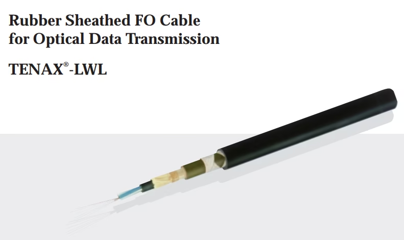
TENAX®-LWL представляет собой высокопроизводительный резиновый оптоволоконный кабель, специально разработанный для надёжной передачи данных и сигналов в экстремальных условиях эксплуатации. Данный кабель сочетает в себе передовые оптические технологии с усиленной механической защитой, что делает его идеальным решением для промышленных применений, где требуется высокая устойчивость к механическим нагрузкам, температурным колебаниям и агрессивным средам.

Что такое резиновый оптоволоконный кабель TENAX-LWL для передачи оптических данных?

TENAX-LWL, rubber sheathed fiber optic cable, industrial fiber optic cable, optical data transmission cable, 50/125 multimode fiber, graded index fiber cable, DIN VDE 0207, DIN VDE 0207-21, ITU-T G.651.1, IEC 60793-2-10, ISO/IEC 11801, TIA-492AAAB, Kevlar reinforced fiber cable, aramid strength member, CSP compound cable, chlorosulfonated polyethylene, crane fiber optic cable, conveyor fiber optic cable, materials handling cable, industrial automation cable, mining fiber optic cable, reeling fiber optic cable, 2000N tensile strength, high bandwidth fiber cable, EMI resistant fiber optic, anti-twist fiber cable, temperature resistant fiber cable, оптоволоконный кабель, промышленный оптический кабель, 工業光纖電纜, 橡膠護套光纖電纜, Anhui Feichun cable, 安徽飞纯电缆, special cable manufacturer, heavy duty fiber optic, outdoor fiber optic cable, flexible fiber optic cable, ST connector fiber cable, SC connector industrial, factory terminated fiber, pigtail fiber optic, VDE certified cable, German standard fiber cable, OM2 industrial fiber, multimode optical cable, high tensile fiber optic, low attenuation fiber, UV resistant fiber cable, ozone resistant cable
The Veriflex range encompasses control cables (SY, CY, YY series), fieldbus cables (Profibus DP/PA, DeviceNet), and Industrial Ethernet cables (Profinet, PUR Ethernet). Available in both PVC and LSZH (Low Smoke Zero Halogen) variants, the portfolio addresses diverse installation environments from standard industrial settings to fire-sensitive locations requiring enhanced safety performance.

What is Veriflex Cable?

Veriflex CY PVC YSLCY, Veriflex SY PVC YSLYSY, Veriflex YY PVC YSLY, Veriflex YY LSZH HSLH, Veriflex CY LSZH HSLCH, Veriflex Screened Bedded LSZH HSLHCH, Veriflex YSLYCY 1kV cable, Veriflex Control PUR-JZ, Veriflex 2XSL(st)CH LSZH, Veriflex DeviceNet Thick FRNC-LSZH, Veriflex DeviceNet Thin LSZH, Veriflex Profibus DP FC L2/FIP PVC, Veriflex Profibus DP FC L2/FIP LSZH, Veriflex Profibus PA PVC, Veriflex Profibus PA FRNC-LSZH, Veriflex Profinet Type A, Veriflex PUR Industrial Ethernet, Veriflex Interface BUS Cable
The International Electrotechnical Commission IEC 61158 Standard covers digital data communications for measurement and control in industrial automation. It has been developed for industrial computer network protocols offering real-time distributed control. This series of standards sets out the protocols for the interconnection of automation and process control system components by fieldbus network systems in manufacturing plants.

What is IEC 61158 Cable?

IEC 61158, IEC 61158 cable, fieldbus cable, Profibus cable, Profibus DP, Profibus PA, Foundation Fieldbus, Foundation Fieldbus H1, ControlNet cable, DeviceNet cable, Interbus cable, industrial automation cable, process control cable, fieldbus communication, PLC cable, IEC 61158, IEC 61784, IEC 61158-2, EN 50170, EN 50254, EN 50325, DIN 19245, fieldbus standard, industrial communication networks, real-time distributed control, digital data communications