
An engineering guide to the VFD motor cable family: PE insulation for low capacitance, aluminium-laminated foil plus tinned copper braid for full-spectrum screening, in a transparent indoor version, a black UV-resistant version and a symmetrical 3PLUS design with three PE cores.
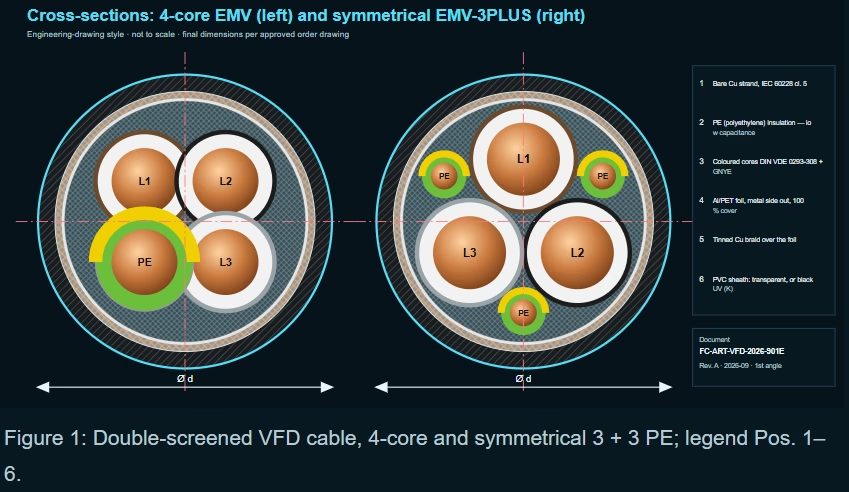
2YSL(St)CY-J 0.6/1 kV EMV: low-capacitance, double-screened cable for frequency converters
An engineering guide to the VFD motor cable family: PE insulation for low capacitance, aluminium-laminated foil plus tinned copper braid for full-spectrum screening, in a transparent indoor version, a black UV-resistant version and a symmetrical 3PLUS design with three PE cores.
1. Reading the designation
2Y = PE insulation; SL = control/connecting cable; (St) = static screen (Al-laminated foil); C = copper braid; Y = PVC sheath; K = black UV-resistant sheath; -J = with GNYE; EMV = EMC (Elektromagnetische Verträglichkeit); 3PLUS = three phases plus three symmetrically arranged PE cores.
Standard constructions across three variants, 1.5–240 mm².
Foil 100 % + tinned Cu braid.
Core/core capacitance at 1.5 mm².
Current capacity at 240 mm², 30 °C.
2. Construction
| Pos. | Element | Material / form | Engineering function |
|---|---|---|---|
| 1 | Conductor | Bare Cu, fine-wire, IEC 60228 cl. 5 | Flexibility; low skin-effect losses with fine wires |
| 2 | Core insulation | PE (polyethylene) | Low permittivity → low capacitance, low dielectric losses |
| 3 | Core identification | Coloured to DIN VDE 0293-308, with GNYE | Phase identification; 3PLUS: 3 phases + 3 split PE cores |
| 4 | Inner screen | Aluminium-laminated polyester foil, metal side out, 100 % coverage | Closes braid gaps at high frequency; contacts the braid |
| 5 | Outer screen | Tinned copper braid | Low-resistance return path; mechanical robustness of the screen |
| 6 | Outer sheath | PVC; transparent (EMV) or black UV-resistant (K versions) | IEC 60332-1; acids, bases, specified oils; black for outdoor use |
3. VFD physics: why ordinary cables cause trouble
Each IGBT switching edge charges the cable capacitance. The resulting current pulses flow partly as common-mode current back to the converter. If the cable screen is poor or badly terminated, this current finds other paths — machine structure, motor bearings, protective earth, neighbouring signal cables — causing EMI, nuisance tripping of RCDs and electrical bearing erosion.
4. Technical data
| Parameter | Value | Engineering note |
|---|---|---|
| Variants | 2YSL(St)CY-J EMV (transparent); 2YSL(St)CYK-J EMV-UV (black); 2YSL(St)CYK-J EMV-3PLUS-UV (black, 3 + 3 PE) | |
| Conductor | Bare copper strand, IEC 60228 class 5 | |
| Core insulation | PE | |
| Core identification | Acc. to DIN VDE 0293-308, coloured cores with GNYE | |
| Stranding | Cores stranded in layers | |
| Screen | Al-laminated polyester foil, metal side outside, 100 % coverage; over it tinned copper braid | Double screen |
| Outer sheath | PVC | |
| Sheath colour | Transparent; K-version: black | Black: UV-resistant, outdoor use |
| Rated voltage U0/U | 0.6/1 kV | Highest permissible operating voltage: AC 700/1 200 V; DC 900/1 800 V |
| Test voltage | 4 kV | |
| Conductor resistance | Acc. to IEC 60228 cl. 5 | |
| Insulation resistance | Min. 20 MΩ × km | |
| Current carrying capacity | See tables (30 °C ambient) | Max. permissible values at 30 °C |
| Capacitance | See tables | Core/core 70–250 nF/km; core/screen 110–410 nF/km |
| Min. bending radius fixed | Ø ≤ 12 mm: 5 × d; ≤ 20 mm: 7.5 × d; > 20 mm: 10 × d | Calculated per size in the tables |
| Min. bending radius moved | Ø ≤ 12 mm: 10 × d; ≤ 20 mm: 15 × d; > 20 mm: 20 × d | |
| Operating temp. fixed | −40 °C / +80 °C | |
| Operating temp. moved | −5 °C / +70 °C | Occasional movement only |
| Conductor temperature | +70 °C operation; +160 °C short-circuit | |
| Burning behaviour | Self-extinguishing and flame-retardant acc. to IEC 60332-1 | |
| Chemical resistance | Largely resistant to acids, bases and specified oils | |
| Compliance | RoHS; 2014/35/EU Low Voltage Directive (CE); LABS-/silicone-free during production |
5. Full data tables
All 45 constructions are listed, including current capacity at 30 °C ambient and both capacitance values. Bending radii are calculated with the diameter-dependent factor for each size. The transparent and black 4-core versions share identical electrical and dimensional data.
| Dimension n × mm² | Item no. (ref.) | Outer Ø mm | Cu index kg/km | Weight kg/km | Current capacity A (30 °C) | C core/core nF/km | C core/screen nF/km | Min. bend fixed mm | Min. bend moved mm |
|---|---|---|---|---|---|---|---|---|---|
| 4 G 1.5 | 1000390 | 10.8 | 95.0 | 212.0 | 18 | 70 | 110 | 5 × d = 54 | 10 × d = 108 |
| 4 G 2.5 | 1000391 | 12.3 | 150.0 | 270.0 | 26 | 80 | 130 | 7.5 × d = 92 | 15 × d = 184 |
| 4 G 4 | 1000392 | 14.5 | 235.0 | 362.0 | 34 | 90 | 150 | 7.5 × d = 109 | 15 × d = 218 |
| 4 G 6 | 1000393 | 16.2 | 320.0 | 582.0 | 44 | 110 | 170 | 7.5 × d = 122 | 15 × d = 243 |
| 4 G 10 | 1000394 | 19.5 | 533.0 | 794.0 | 61 | 120 | 190 | 7.5 × d = 146 | 15 × d = 292 |
| 4 G 16 | 1000648 | 22.4 | 789.0 | 1,188.0 | 82 | 130 | 220 | 10 × d = 224 | 20 × d = 448 |
| 4 G 25 | 1000649 | 27.0 | 1,236.0 | 1,713.0 | 108 | 145 | 230 | 10 × d = 270 | 20 × d = 540 |
| 4 G 35 | 1000650 | 30.7 | 1,662.0 | 2,402.0 | 135 | 150 | 260 | 10 × d = 307 | 20 × d = 614 |
| 4 G 50 | 1000651 | 35.3 | 2,345.0 | 2,718.0 | 168 | 175 | 290 | 10 × d = 353 | 20 × d = 706 |
| 4 G 70 | 1000500 | 40.2 | 3,196.0 | 3,636.0 | 207 | 180 | 300 | 10 × d = 402 | 20 × d = 804 |
| 4 G 95 | 1000501 | 45.0 | 4,316.0 | 4,700.0 | 250 | 195 | 320 | 10 × d = 450 | 20 × d = 900 |
| 4 G 120 | 1000003 | 52.1 | 5,435.0 | 5,699.0 | 292 | 215 | 340 | 10 × d = 521 | 20 × d = 1042 |
| 4 G 150 | 1001850 | 55.2 | 6,394.0 | 7,043.0 | 335 | 230 | 360 | 10 × d = 552 | 20 × d = 1104 |
| 4 G 185 | 1002368 | 62.9 | 7,639.0 | 8,384.0 | 385 | 240 | 380 | 10 × d = 629 | 20 × d = 1258 |
| 4 G 240 | 1002702 | 69.8 | 10,013.0 | 11,292.0 | 453 | 250 | 410 | 10 × d = 698 | 20 × d = 1396 |
| Dimension n × mm² | Item no. (ref.) | Outer Ø mm | Cu index kg/km | Weight kg/km | Current capacity A (30 °C) | C core/core nF/km | C core/screen nF/km | Min. bend fixed mm | Min. bend moved mm |
|---|---|---|---|---|---|---|---|---|---|
| 4 G 1.5 | 1002327 | 10.8 | 95.0 | 212.0 | 18 | 70 | 110 | 5 × d = 54 | 10 × d = 108 |
| 4 G 2.5 | 1002328 | 12.3 | 150.0 | 270.0 | 26 | 80 | 130 | 7.5 × d = 92 | 15 × d = 184 |
| 4 G 4 | 1002331 | 14.5 | 235.0 | 362.0 | 34 | 90 | 150 | 7.5 × d = 109 | 15 × d = 218 |
| 4 G 6 | 1002744 | 16.2 | 320.0 | 582.0 | 44 | 110 | 170 | 7.5 × d = 122 | 15 × d = 243 |
| 4 G 10 | 1002329 | 19.5 | 533.0 | 794.0 | 61 | 120 | 190 | 7.5 × d = 146 | 15 × d = 292 |
| 4 G 16 | 1002337 | 22.4 | 789.0 | 1,188.0 | 82 | 130 | 220 | 10 × d = 224 | 20 × d = 448 |
| 4 G 25 | 1002323 | 27.0 | 1,236.0 | 1,713.0 | 108 | 145 | 230 | 10 × d = 270 | 20 × d = 540 |
| 4 G 35 | 1002322 | 30.7 | 1,662.0 | 2,402.0 | 135 | 150 | 260 | 10 × d = 307 | 20 × d = 614 |
| 4 G 50 | 1002365 | 35.3 | 2,345.0 | 2,718.0 | 168 | 175 | 290 | 10 × d = 353 | 20 × d = 706 |
| 4 G 70 | 1002745 | 40.2 | 3,196.0 | 3,636.0 | 207 | 180 | 300 | 10 × d = 402 | 20 × d = 804 |
| 4 G 95 | 1002387 | 45.0 | 4,316.0 | 4,700.0 | 250 | 195 | 320 | 10 × d = 450 | 20 × d = 900 |
| 4 G 120 | 1002746 | 52.1 | 5,435.0 | 5,699.0 | 292 | 215 | 340 | 10 × d = 521 | 20 × d = 1042 |
| 4 G 150 | 1002330 | 55.2 | 6,394.0 | 7,043.0 | 335 | 230 | 360 | 10 × d = 552 | 20 × d = 1104 |
| 4 G 185 | 1002293 | 62.9 | 7,639.0 | 8,384.0 | 385 | 240 | 380 | 10 × d = 629 | 20 × d = 1258 |
| 4 G 240 | 1002747 | 69.8 | 10,013.0 | 11,292.0 | 453 | 250 | 410 | 10 × d = 698 | 20 × d = 1396 |
| Dimension n × mm² | Item no. (ref.) | Outer Ø mm | Cu index kg/km | Weight kg/km | Current capacity A (30 °C) | C core/core nF/km | C core/screen nF/km | Min. bend fixed mm | Min. bend moved mm |
|---|---|---|---|---|---|---|---|---|---|
| 3 x 1.5 + 3 G 0.25 | 1003431 | 10.2 | 91.0 | 144.0 | 18 | 70 | 110 | 5 × d = 51 | 10 × d = 102 |
| 3 x 2.5 + 3 G 0.5 | 1002390 | 11.6 | 152.0 | 264.0 | 26 | 80 | 130 | 5 × d = 58 | 10 × d = 116 |
| 3 x 4 + 3 G 0.75 | 1003138 | 13.2 | 224.0 | 333.0 | 34 | 90 | 150 | 7.5 × d = 99 | 15 × d = 198 |
| 3 x 6 + 3 G 1 | 1002719 | 15.0 | 298.0 | 429.0 | 44 | 110 | 170 | 7.5 × d = 112 | 15 × d = 225 |
| 3 x 10 + 3 G 1.5 | 1002660 | 18.4 | 491.0 | 692.0 | 61 | 120 | 190 | 7.5 × d = 138 | 15 × d = 276 |
| 3 x 16 + 3 G 2.5 | 1002890 | 21.5 | 723.0 | 979.0 | 82 | 130 | 220 | 10 × d = 215 | 20 × d = 430 |
| 3 x 25 + 3 G 4 | 1002720 | 25.3 | 1,138.0 | 1,404.0 | 108 | 145 | 230 | 10 × d = 253 | 20 × d = 506 |
| 3 x 35 + 3 G 6 | 1002721 | 28.3 | 1,535.0 | 1,813.0 | 135 | 150 | 260 | 10 × d = 283 | 20 × d = 566 |
| 3 x 50 + 3 G 10 | 1003001 | 33.0 | 2,208.0 | 2,501.0 | 168 | 175 | 290 | 10 × d = 330 | 20 × d = 660 |
| 3 x 70 + 3 G 10 | 1002661 | 36.9 | 2,871.0 | 3,112.0 | 207 | 180 | 300 | 10 × d = 369 | 20 × d = 738 |
| 3 x 95 + 3 G 16 | 1002662 | 40.9 | 3,953.0 | 4,492.0 | 250 | 195 | 320 | 10 × d = 409 | 20 × d = 818 |
| 3 x 120 + 3 G 16 | 1002722 | 46.5 | 4,836.0 | 5,301.0 | 292 | 215 | 340 | 10 × d = 465 | 20 × d = 930 |
| 3 x 150 + 3 G 25 | 1002380 | 51.0 | 5,421.0 | 6,097.0 | 335 | 230 | 360 | 10 × d = 510 | 20 × d = 1020 |
| 3 x 185 + 3 G 35 | 1002999 | 58.2 | 7,041.0 | 7,597.0 | 382 | 240 | 380 | 10 × d = 582 | 20 × d = 1164 |
| 3 x 240 + 3 G 50 | 1003427 | 63.0 | 9,148.0 | 10,379.0 | 453 | 250 | 410 | 10 × d = 630 | 20 × d = 1260 |
6. 4-core versus symmetrical 3PLUS
In a 4-core cable the single PE sits asymmetrically relative to the three phases, so the phase currents induce a net voltage on it. In 3PLUS, three smaller PE cores sit in the gaps between the phases; the induced voltages cancel. The 3PLUS version is also smaller and lighter at the same phase cross-section, since the three PE cores fill interstices.
| 4-core | 3PLUS | 4-core Ø mm | 3PLUS Ø mm | 4-core kg/km | 3PLUS kg/km |
|---|---|---|---|---|---|
| 4 G 1.5 | 3 x 1.5 + 3 G 0.25 | 10.8 | 10.2 | 212.0 | 144.0 |
| 4 G 2.5 | 3 x 2.5 + 3 G 0.5 | 12.3 | 11.6 | 270.0 | 264.0 |
| 4 G 4 | 3 x 4 + 3 G 0.75 | 14.5 | 13.2 | 362.0 | 333.0 |
| 4 G 6 | 3 x 6 + 3 G 1 | 16.2 | 15.0 | 582.0 | 429.0 |
| 4 G 10 | 3 x 10 + 3 G 1.5 | 19.5 | 18.4 | 794.0 | 692.0 |
| 4 G 16 | 3 x 16 + 3 G 2.5 | 22.4 | 21.5 | 1,188.0 | 979.0 |
| 4 G 25 | 3 x 25 + 3 G 4 | 27.0 | 25.3 | 1,713.0 | 1,404.0 |
| 4 G 35 | 3 x 35 + 3 G 6 | 30.7 | 28.3 | 2,402.0 | 1,813.0 |
| 4 G 50 | 3 x 50 + 3 G 10 | 35.3 | 33.0 | 2,718.0 | 2,501.0 |
| 4 G 70 | 3 x 70 + 3 G 10 | 40.2 | 36.9 | 3,636.0 | 3,112.0 |
| 4 G 95 | 3 x 95 + 3 G 16 | 45.0 | 40.9 | 4,700.0 | 4,492.0 |
| 4 G 120 | 3 x 120 + 3 G 16 | 52.1 | 46.5 | 5,699.0 | 5,301.0 |
| 4 G 150 | 3 x 150 + 3 G 25 | 55.2 | 51.0 | 7,043.0 | 6,097.0 |
| 4 G 185 | 3 x 185 + 3 G 35 | 62.9 | 58.2 | 8,384.0 | 7,597.0 |
| 4 G 240 | 3 x 240 + 3 G 50 | 69.8 | 63.0 | 11,292.0 | 10,379.0 |
7. Installation and termination
8. Comparison
| Type | Insulation | Screen | Capacitance | Typical use |
|---|---|---|---|---|
| PVC-insulated YCY | PVC (εr ≈ 5–6) | Cu braid ≈85 % | High | Short VFD leads, control |
| 2YSL(St)CY-J EMV | PE (εr ≈ 2.3) | Foil 100 % + Cu braid | Low (70–250 nF/km core/core) | VFD motor leads, long runs |
| … EMV-3PLUS-UV | PE | Foil + braid | Low; symmetrical PE | Large drives, ≥ 10 mm²; outdoor |
| NYCWY (concentric) | PVC | Concentric Cu wires | High | Fixed distribution, not optimised for VFD |
9. Design calculations
10. Certification, traceability and FAQ
This cable family is RoHS-conform, CE-conform to the 2014/35/EU Low Voltage Directive and LABS-/silicone-free during production, with flame behaviour to IEC 60332-1. FeiChun Cable holds a complete export certification portfolio — including CE, UKCA, VDE, EAC, ATEX and IECEx — and every certificate supplied is checked against the exact type, voltage, factory and standard of the order. Routine tests include conductor resistance, 4 kV voltage test, insulation resistance, screen continuity and capacitance.
Why PE insulation rather than PVC or XLPE?
PE has a relative permittivity of about 2.3, less than half that of PVC. Lower capacitance means lower capacitive charging current from each PWM edge, less drive derating and longer permissible motor-cable lengths.
When should I choose 3PLUS?
For larger drives — typically from about 10 mm² — and long leads. Three PE cores placed symmetrically between the phases cancel the induced voltages on the PE path, reducing circulating currents and bearing currents.
Transparent or black?
Transparent for indoor installation; black K-versions have a UV-resistant sheath for outdoor use. Electrical data are identical.
Can I earth the screen at one end only?
Not for VFD motor leads. Bond 360° at both the drive and the motor to give the common-mode current a low-impedance return path.
What do 700/1 200 V and 900/1 800 V mean?
The highest permissible continuous operating voltages: 700 V phase-to-earth and 1 200 V phase-to-phase for AC, and 900/1 800 V for DC, giving margin for VFD DC-link and reflected-wave peaks.
Is it a drag-chain cable?
No. Fixed laying and occasional free movement without tensile stress or forced guidance.
Technical and project enquiries: [email protected]
+86 13855123218


